

�@
�@
| Question | Answer | ||||||||||||||||||||||||||||||||||||||||||||||||||||||||||||||||||||||||||||||||||||||||||||||||||||||||||||||||||||||||||||||||||||||||||
| Verilog�T�u�Z�b�g�ŁA�T�|�[�g���Ă���d�l�́H | Specify�@Section�APLI�AIEEE1364-Verilog-2001��v�\�����T�|�[�g���܂��B �ȉ��́AVersion�@1.45�ł̃T�|�[�g�\�����X�g�ł��B No.�́AStuart�@Sutherland���́uVerilog2001:�@A�@Guide to The New Features of the Verilog Hardware Description Language�v�ł�No.�ł��B
|
||||||||||||||||||||||||||||||||||||||||||||||||||||||||||||||||||||||||||||||||||||||||||||||||||||||||||||||||||||||||||||||||||||||||||
| Verilog����VHDL�̃g�����X���[�^�͂Ȃ��̂ł����H | ����܂���B���ʁA�J���\�������܂���B | ||||||||||||||||||||||||||||||||||||||||||||||||||||||||||||||||||||||||||||||||||||||||||||||||||||||||||||||||||||||||||||||||||||||||||
| �����VersionUp�\��́H |
verilog HDL 64�r�b�g�V�~�����[�^�ɂ�����r�A�l�@���Ă݂܂����B �ŐV���x���`�}�[�N�����ł��B���E���x���̃V�~�����[�V�������x�ɂȂ�܂����B �v���ł�CPUID/MAC�A�h���X���C�Z���X�h���[�U�́A���ł����p�\�ł��BURL�́A3.79E�ȍ~��Help�ɋL�ڂ��Ă��܂��B�i���ŋy�сA���̌�̃��ł́A���C�Z���X�̃��b�N�͂���܂���B���ɁA�g�`�t�Œ����̃V�~�����[�V�����ł́A�p�t�H�[�}���X�I��64�r�b�g�ł������߂��܂��B�j SV�@�\�̎����ɂ��ẮA�l�I����ɂ��J�����P�N�ԃy���f�B���O���邱�Ƃɂ��܂����B �@���郆�[�U�l���AMIXI�ŁA�R�~���j�e�B�𗧂��グ�Ă��������܂����B�����̂�����́A ���C�y�ɂ��Q���������B |
||||||||||||||||||||||||||||||||||||||||||||||||||||||||||||||||||||||||||||||||||||||||||||||||||||||||||||||||||||||||||||||||||||||||||
| VHDL����AVerilog�ւ̃g�����X���[�^�́A���ł��ϊ��ł���̂ł����H | �@�������B�Ή��s�\�ȋL�q�͂���܂��B �@�E���Z�q��` �@�EIEEE���C�u�����ȊO�̋L�q �@�EConfig��. �@�EAttribute �@�EVITAL�@�APRIMITIVE��`�A���̑� �@���ł��B�@ �@ ���Ƀn�[�h�E�F�A���牓���L�q���ƁA�\�[�X�C�����K�v�ƂȂ�m�����オ��܂��B����́A�g�����X���[�^�̖��Ƃ������́A���������Ⴄ����Ȃ̂Ŗ���������Ƃ������Ƃ�������܂���BVeritak�ł͊g���d�l�ŃV�~�����[�V�������x���ł́A�\�[�X�C�����ł��邾�����Ȃ��Ȃ�悤�ɔz�����Ă��܂��B �Ȃ��ASystem�@Verilog�ł́AVHDL����̕ϊ����S�����Ȃ�y������錩�ʂ��ł��BVertak�@�V�~�����[�^�{�̂�System�@Verilog�֑Ή�����ɏ]���AVeritak�g�����X���[�^��System�@Verilog�ւ̕ϊ��ɐ�ւ��čs���܂��B |
||||||||||||||||||||||||||||||||||||||||||||||||||||||||||||||||||||||||||||||||||||||||||||||||||||||||||||||||||||||||||||||||||||||||||
| �g�����X���[�^��ʂ�����̒��쌠�́H | �g�����X���[�^�́A���쌠���咣���܂���B ����҂�COPYRIGHT�\�����c��悤�ɂȂ��Ă��܂��B |
||||||||||||||||||||||||||||||||||||||||||||||||||||||||||||||||||||||||||||||||||||||||||||||||||||||||||||||||||||||||||||||||||||||||||
| Veritak�̖ڎw���Ă�����̂́H | �ESystemVerilog ���݁AVeritak�́AVerilog2001�����d�l�ł����A�v���v���Z�b�T���A3K�AGUI��40K,�A�R���p�C���E�V�~�����[�^��180K�s�ɂȂ��Ă��܂��B �@ �ŏI�I�ɂ�SystemVerilog�̎�����ڎw���Ă��܂����A�����30���s���x�̋L�q���K�v�Ǝv���܂��B���ꂪ�ł���ƁA�N���X,struct,typedef,union,enum����C/C++�I�L�q���ł���悤�ɂȂ�܂��BSystemVerilog��=Verilog2001�@+�@C++�݂����d�l�ŁA���Ȃ��K�͂Ȍ���d�l�ł��B �@ ���V�~�����[�^�̊J������ɂ��ā� �EPC�̃�������CPU�������\�ɂȂ�A�́A���\���������Ă��������Q�[�g�̃V�~�����[�V������Veritak��15SEC�ŏo���Ė������Ă���ƁA100���Q�[�g���x����RTL�V�~�����[�V�����ł́u�x���v�ƌ����Ă��܂��܂��B�܂��A�ŋ߂̃T�|�[�g����ł����A32MB��SDRAM�����f�����O���Ă��郆�[�U�����āA�����炪�����Ă��܂��܂����B�iVerilog����4�l�Ȃ̂ł���Object������64MB�H���Ă��܂��BVHDL�ł�128MB�j���ꂾ��PC�������\�ɂȂ��Ă��A�܂�CPU�ƃ������͑���܂���A�Ƃ�����肱�̊W�́A�����ς�邱�Ƃ��Ȃ��i�^���ɋ߂��j�悤�ȋC�����܂��BVHDL��Verilog�ł́A�P���ɕK�v�������͔{�Ⴄ���i���̌��ʃV�~�����[�V�������x��Verilog�̕��������ł��B�i�܂��ASystemVerilog�ł́ASpeed�@Accelerate�p��2�l������܂��B�j�����\��CPU�EASIC�����Verilog���D�܂��̂͂����ɂ���܂��B�j�J������́A���̎���AC++�łȂ��Ă������悤�ȋC�����܂����A�V�~�����[�V�������x���l����ƑI���̗]�n�͂Ȃ��̂ł��B �EWEB�@EDITION/WEB�@PACK�{Veritak �t���[��WEB�@Edition�ł��Q�[�g�K�͂ł����A����RAM���܂߂��100���Q�[�g�K�͂̊J�����\�Ȏ���ɂȂ��Ă��܂����B�v�c�[������������A�Ǝ��A�[�L�e�N�`����CPU�EDSP�����ł��v�ł��܂��B�������o�X���́A16�r�b�g�Ƃ�32�r�b�g���O���o�X���ɐ�������邱�Ƃ͂���܂��APLL��CLOCK���g�����v���̂܂܂ł��BFPGA�̔\�͈͂�̑O�̂���Ƃ͔�ו��ɂȂ�Ȃ����炢�傫�Ȃ��̂ɂȂ��Ă��܂��B����v�Z����ł́A�y���e�B�A���𗽉킷�邱�Ƃ��\�ł��傤�B���̂悤�Ȑ��ݔ\�͂�����FPGA��H/W�����������悭�v���Z�V���O�i�R�[�f�B���O�j���邽�߂̐v�c�[���ƂȂ邱�Ƃ�ڎw���Ă��܂��B �ENYSL�@FPGA�@CPU�R�A ���܂͂����A�u�~�j�R���s���[�^�v������ɂȂ��Ă��܂����A���̐́ACPU�́A���b�N�ɂ͂����Ă��܂����B�t���b�s�[�f�B�X�N��A�n�[�h�f�B�X�N�̃R���g���[�����ӂ��u�`���l���v�ƌ����āA�e�X�A����PC�{�[�h�ȏ�ɑ傫�����TTL/ECL/�Q�[�g�A���[�Őv����Ă��܂����B���W�X�^���Z300ns�����ꂵ������ł��B��������HP64000�G�~�����[�^�⍑�Y����16�r�b�g�v���Z�b�T��v�����D�G�Ȑl�B���_�Ԍ��Ȃ���A����Ȑl�B���_�̏�̂悤�ȑ��݂Ɋ����Ă��܂����B68000�̐v��100�l�����������ƌ���ꂽ����ł��B���炭���Ď����Q�[�g�A���[��v����悤�ɂȂ�܂������A�Q�[�g�A���[��2K�Q�[�g��v����̂�2�����ł͂����A�Ƃ�������i�Ƃ̂��Ƃ���o���Ă��܂��B�i����Veritak���[�U�i��[�̃V�X�e��LSI�f�U�C�i�[�j�ɂ��ƍŋ߂́A100K�Q�[�g/�l�̐��Y���������ł��B�u���̊�������܂��ˁB�j �@����͕ς��AHDL�Ƙ_��������ŁA�N�ł��i�_���v�̃G�L�X�p�[�g�łȂ��Ƃ��jFPGA�ŁA�I���W�i��CPU��v�ł��鎞��ɂȂ�܂����B����AFPGA�̕Ћ���CPU��E���Ă������Ƃ��ł���ʂ�FPGA�̃��\�[�X���L�x�ɂȂ�܂����B�����A�����d�l�̎����̃v���Z�b�T�v���A���ۂɑ��点��ł��邱�Ƃ��ł��܂��BGCC��MD��������AC/C++/Fortran/ADA/JAVA�����点�邱�Ƃ��\�ł��傤�BC������A���̏��OS�����点�邱�Ƃ��ł��܂��B Veritak�J���Ҏ��g�AH/W�Z�p�҂ł��̂ŁAFPGA�pCPU�R�A��v���Ă݂����Ǝv���Ă��܂��B�������A�I�[�v���R�A�̌݊�CPU�R�A�ł́A�V�~�����[�^�ő��点��͖̂��Ȃ��Ƃ��A���ۂ�H/W�����Đ��ɂ����ƂȂ�ƒ��쌠�A�p�e���g�̖��͂��Ă܂��܂��B�܂��A�p�e���g�̖����N���A���Ă��AGPL�ł̓\�[�X�J���̋`���������܂��B �Ƃ���Ń}�C�N���v���Z�b�T���a�����Ĉȗ���{�A�[�L�e�N�`���͕ς���Ă��܂���B�����ŁA�͂ꂽ�Z�p�݂̂��g�p����FPGA�pCPU�R�A�iGCC�œ����j��NYSL�i���p�e���g�̔��肪�Ȃ��j��v���Ă݂����ƍl���Ă��܂��B�����ALINUX��{�b�g��������CPU�ő��点�Ă݂����ł��ˁB�����H/W�Z�p�҂Ƃ��Ă̖��ł��B�O�ƂP�����̕������E����A�Z�p�̐ςݏd�˂ɂ���đs��Ȑ��E�ɓW�J�����s�v�c��̌����Ă݂����Ǝv���܂��B |
||||||||||||||||||||||||||||||||||||||||||||||||||||||||||||||||||||||||||||||||||||||||||||||||||||||||||||||||||||||||||||||||||||||||||
| ��Ђ̎葱����A���Ϗ��A���������v��̂ł����B | ���[���ł��w��������A�Ή����܂��B���ϕ��@�A�����ɂ��Ă��w������������A�Ή��\�ł��B | ||||||||||||||||||||||||||||||||||||||||||||||||||||||||||||||||||||||||||||||||||||||||||||||||||||||||||||||||||||||||||||||||||||||||||
| XL��VCS���̃v���e�N�g���C�u����́H | �Ή����Ă��܂���B�����I�ɂ��Ή��ł��܂���B | ||||||||||||||||||||||||||||||||||||||||||||||||||||||||||||||||||||||||||||||||||||||||||||||||||||||||||||||||||||||||||||||||||||||||||
| �ǂ�Ȑl��Veritak���g���Ă��܂����H | Veritak�́A������HDL�V�~�����[�^�ł��B10GB�ȏ�̈��k�g�`Save�iVCD�ł́A100GB�ȏ�ɑ����j�A����ɍ����������R���p�C��Version�A64�r�b�g���Ή��ASystemVerilog�Ή����A�@�\�����ɂ����g��ł��܂��B LSI�J����Ƃ̖w�ǂ̎��Ԃ��ARTL�L�q�ƌ��؍�Ƃɔ�₳��邱�Ƃɒ��ڂ��āARTL�̃f�o�b�O�����A�b�v�Ƀt�H�[�J�X���Ă��܂��BLSI�G���W�j�A�ɂ��LSI�G���W�j�A�ׂ̈̃V�~�����[�^�ł��B LSI�f�U�C���G���W�j�A/Dr������Ŏg���V�~���[���[�^�Ƃ��āA�܂��AVerilog�̌���K���p�A���샍�{�b�g���A�m�I�ȓd�q�H��Ŏg������A�Ɨl�X�̂悤�ł��B���R�́A�悭������܂��A���{�E�C�O���A�����҂̕��������悤�ȋC�����܂��B�ܘ_�A�����o���o����LSI�G���W�j�A�̕����吨��������Ⴂ�܂��B�i���������܂ŁA���{��LSI��v����Ă����v�Ȋ�Ƃł́A��́A���g���̕������锤�ł��B�jTODOLIST�����Ă���������A�����̉��P��ẮA���Ɩ�����UP�Ƀt�H�[�J�X������Ăł��邱�Ƃ��������肢�������邱�ƂƎv���܂��B ���[�U�̊F�l����̂��ӌ��A���v�]�����������Ă��̋@�\�̕K�v���ɓ��S���邱�Ƃ������ł��B���ɁA���{�̃v���t�F�b�V���i��LSI�f�U�C�i�̕��X����́A�����̂����������������A�}���ɉ��P���邱�Ƃ��ł��܂����B�PUser�Ƃ��Ă���ώg���Ղ��Ȃ����Ǝv���܂��B���N�O�̃����[�X�Ƃ́A��ׂ�ׂ�������܂���B�����ŁA��Ж��Ƃ����O�������Ă����\���グ�邱�Ƃ͂ł��܂��AUser���ő��Contributer�ł��B �{���ɂ��肪�Ƃ��������܂��B Veritak����g���Đ���A���{������I�[�v���R�A�Ő��E�ɖ���y����l���o�Ă��Ă����Ί������ł��B |
||||||||||||||||||||||||||||||||||||||||||||||||||||||||||||||||||||||||||||||||||||||||||||||||||||||||||||||||||||||||||||||||||||||||||
| �p��ł��o��Ƃ̂��ƂŊy���݂ɂ��Ă��܂��B���{����A���E�Ɍ����āA���������\�t�g�E�F�A�̍v�����ł��邱�Ƃ͂��炵�����Ƃ��Ǝv���܂��B�p��ł��ł���A�ꏏ�Ɏd�������Ă���C�O�̗F�l�Ƀv���[���g�������Ǝv���Ă��܂��B �E�E�E�B ���̍ہA�������C�Z���X�����x�����A�ނɏ��n���邱�Ƃ͔F�߂Ē�����ł��傤���B |
3.15A���m�[�h���b�N�ɂȂ�܂����B | ||||||||||||||||||||||||||||||||||||||||||||||||||||||||||||||||||||||||||||||||||||||||||||||||||||||||||||||||||||||||||||||||||||||||||
| From the licensing it was not clear to me how many licenses are needed
if one person runs the regressions over 5-10 machines. It is clear for interactive use as it is one license per person using Veritak. |
1 license /PC is required. | ||||||||||||||||||||||||||||||||||||||||||||||||||||||||||||||||||||||||||||||||||||||||||||||||||||||||||||||||||||||||||||||||||||||||||
| One question that the group manager at my client's company has is if he gets a lot of licenses of Veritak, what kind of support he should expect over the next few years. | Nothing special,same as your client were you. |
||||||||||||||||||||||||||||||||||||||||||||||||||||||||||||||||||||||||||||||||||||||||||||||||||||||||||||||||||||||||||||||||||||||||||
| �w�������Ƃ�����A���C�Z���X�������ďo�鎖���l�����܂��B �w�����������ȊO��PC�̍ڂ���ꍇ�ɂ͊����t���ɂ��邩 �t���[�e�B���O�E���C�Z���X���Ɨǂ��̂ł����A�ǂ��ł��傤���B |
3.15A���A���C�Z���X�������m�[�h���b�N�ɕύX���܂����B �@ |
||||||||||||||||||||||||||||||||||||||||||||||||||||||||||||||||||||||||||||||||||||||||||||||||||||||||||||||||||||||||||||||||||||||||||
| Veritak�̊J���ƃT�|�[�g������l�ł���Ă���̂ł��傤��?���������Ȃ琦��.. | �����ł��B�v���ȃT�|�[�g��S�����Ă��܂��B | ||||||||||||||||||||||||||||||||||||||||||||||||||||||||||||||||||||||||||||||||||||||||||||||||||||||||||||||||||||||||||||||||||||||||||
���C�Z���X�̌`�Ԃ�CPU ID�ɂ��m�[�h���C�Z���X�ֈڍs���������قǒm��܂����B ��ЂƎ����Veritak�����p���Ă�����̂Ƃ��āA�ǂ̂悤�ȑΉ������ׂ����l���Ă��܂��܂��B ���W�X�g�ς݂̋����[�U�[�́A���ʂǂ̂悤�ɂ����낵���ł��傤���H |
�m�[�h���b�N���C�Z���X�́A�V���ɍw���������ɓK�p���܂��B�����C�Z���X���[�U(Veritak3.15A�ȑO�ɍw�����ꂽ���́A�����I��Pro�ň����ɂȂ��Ă���܂��B���݂̃V�F�A�E�F�A�iBasic�j�ł́A�g�p�ł��܂���B���܂łǂ���A�����g�ł��g���ɂȂ������A���R�ɃA�b�v�f�[�g�������̂���ЁE����E�w�Z�E�������E���������킸�A����ł����g�����������B |
||||||||||||||||||||||||||||||||||||||||||||||||||||||||||||||||||||||||||||||||||||||||||||||||||||||||||||||||||||||||||||||||||||||||||
���C�Z���X���p���I�ɒlj����Ă������Ǝv���̂ł����C�m�[�h���b�N�ł��� �Ǘ�������Ȃ��ō���܂����C�����I�ɂ̓t���[�e�B���O�E���C�Z���X�ɂ��Ē� ���Ə�����܂��D |
�����I�Ɍ����������Ǝv���܂����A���ʌ��݂̃X�^�C���ł��B | ||||||||||||||||||||||||||||||||||||||||||||||||||||||||||||||||||||||||||||||||||||||||||||||||||||||||||||||||||||||||||||||||||||||||||
Pro�łƃV�F�A�E�F�A�łɂ����A
�Ƃ��ĕ����܂����B�@�\�̈Ⴂ�ɂ��ẮAWEB�@tutorial 6�����������������B �V�F�A�E�F�A�ł̃A�b�v�ɂ��ẮAWEB�T�C�g�Ń��W���[�@Version�A�b�v���ɃA�b�v���܂��BVector�́A�s����Ɂi�������Ɉ����x�j����ł�ǂ�������`�ɂȂ�܂��B�Ȃ��A���d���ł��g���ł�����A�v���ȃT�|�[�g��Pro�ł����w�����������������肢�������܂��B
|
|||||||||||||||||||||||||||||||||||||||||||||||||||||||||||||||||||||||||||||||||||||||||||||||||||||||||||||||||||||||||||||||||||||||||||
| ����Veritak�z�[���y�[�W����_�E�����[�h����Pro�ł����p�Ŏg���Ă��܂����AVector�ōw������ꍇ�͈�x�A���C���X�g�[�����ăC���X�g�[�����Ȃ�����߂ł��傤���H
�]�����Ԃ�VHDL�̃V�~�����[�V�����̕]�����������̂ł���.. ModelSim�̂悤�ɕ����o�[�W�������C���X�g�[���ł��܂��ł��傤���H |
�A���C���X�g�[������K�v�͂Ȃ��ł��B�������p�����͌����ʂɂȂ��Ă���܂��āA�A���C���X�g�[���E�C���X�g�[���ɂ�����炸�A16���Ő�܂��B�T�C�g�ł����W���[�����[�X���ɃA�b�v����悤�ɂ��܂����B�T�C�g�ɂ���Basic�ł́A���V�F�A�E�F�A�łƂ́A���C�Z���X���Ă��܂��̂ŁA�V���������p�A���]�����\�ł��B�i���V�F�A�E�F�A�Ń��C�Z���X�ł͓����܂���j ����Version�C���X�g�[���͑Ή����Ă��܂���i�Ō�ɃC���X�g�[�������̂��o�^����܂��j���A�C���X�g�[���t�H���_��VeritakWin.Exe�����C���v���O�����ŁA����� �A�C�R��������A����Version���Ăяo���܂��B�i�����N���ɂ��ẮAF.A.Q.345�����Q�Ƃ��������B�j VHDL�g�����X���[�^�̂��Ƃł��傤���H���̃c�[���́A���݃T�|�[�g���Ă��܂���B�i����ƌ���ɂ��ẮAF.A.Q.238/242/312/317/181�����Q�Ƃ��������B�j |
||||||||||||||||||||||||||||||||||||||||||||||||||||||||||||||||||||||||||||||||||||||||||||||||||||||||||||||||||||||||||||||||||||||||||
| �{�����[���E�f�B�X�J�E���g�́A���������Ă��A�S�̃I�[�_�[�ł��傤���H | �f�B�X�J�E���g��2007�N���ŏI���������܂����B ���ɍw���ς݂ŁA���C�Z���X�𐿋�����Ă��Ȃ����q�l�́A�Ȃ�ׂ���N�ȓ��Ɋ�������悤�ɂ��肢�������܂��B |
||||||||||||||||||||||||||||||||||||||||||||||||||||||||||||||||||||||||||||||||||||||||||||||||||||||||||||||||||||||||||||||||||||||||||
| �o�b�̂g�n�r�s�@�h�c�̕ύX�� ��x�p�X���[�h�s������ł������ŕύX�͉\�ł��傤���B |
��{�I�Ƀm�[�h���b�N�ł��̂ŁA�C���X�g�[������PC���̏ᓙ�ɂ��g�p�s�\�ɂȂ����ꍇ�Ɍ��点�Ă��������Ă���܂����APro1�ɂ��ẮA3�N�Ԃ́A���̎|���\���o����������A�����ōēx���C�Z���X�𑗕t���Ă���܂��B | ||||||||||||||||||||||||||||||||||||||||||||||||||||||||||||||||||||||||||||||||||||||||||||||||||||||||||||||||||||||||||||||||||||||||||
| �A�b�v�O���[�g�ɂ��� | Pro�|�P���C�Z���X�ł��w�����ꂽ���́A���ナ���[�X����邷�ׂĂ�Upgrade/Update�ɑΉ����܂��B | ||||||||||||||||||||||||||||||||||||||||||||||||||||||||||||||||||||||||||||||||||||||||||||||||||||||||||||||||||||||||||||||||||||||||||
| �U�������ɂ��ă��C�Z���X���s�� �̐U���ł���낵���ł��傤���B |
�͂��A����������2-3����������̂́A��肠��܂���B | ||||||||||||||||||||||||||||||||||||||||||||||||||||||||||||||||||||||||||||||||||||||||||||||||||||||||||||||||||||||||||||||||||||||||||
| Veritak-Pro1�̍w�����������Ă���܂��B Veritak-Pro1�̃��C�Z���X�ɂ��Ď��₳���ĉ������B > �C���X�g�[������PC���̏ᓙ�ɂ��g�p�s�\�ɂȂ����ꍇ�A�������ł́A > �������̊ԁA�����Ȃ��ł�3�N�ԁA���̎|���\���o����������A > �ēx���C�Z���X�𑗕t�������܂��B �Ƃ���܂����A3�N�Ԃ̈Ӗ��ɂ��Ď���ł��B �Ⴆ�A �@ 2007/11�Ɂ@Veritak-Pro1���w�����APC�ɃC���X�g�[�� �A 2008/12 �� PC�����ւ��B�@�VPC�Ɂ@Veritak-Pro1�C���X�g�[��(���C�Z���X�� ���s) �B 2010/12 �� PC�����ւ� �ƂȂ����ꍇ�ɁA�B�̎��_�� Veritak-Pro1 ���g�p����ꍇ�A �@�̎��_(����C���X�g�[�����i�w�����j)����3�N�o�߂��Ă��邽�߁A���C�Z���X �Ĕ��s�s�ƂȂ�̂ł��傤���H ����Ƃ��A�A�̎��_(�ăC���X�g�[����)����3�N�ȓ��Ȃ̂Ń��C�Z���X�Ĕ��s�\ �ƂȂ�̂ł��傤���H |
���e�͂��������B���w������3�N�ԂƉ��߂��Ă��������B��̏ꍇ�A10�N10����PC���������Ƃ��\���o������A�ēx���C�Z���X�s���܂��B�������A10�N12���ł́A���s�������܂���B�Ȃ��A���C�Z���X���̂́A����PC�ɉi���ł��̂ŁA�̏Ⴕ�Ȃ�����APro1�̏ꍇ�́AUpdate/Upgrade��K���s�����Ƃ��o���܂��B |
||||||||||||||||||||||||||||||||||||||||||||||||||||||||||||||||||||||||||||||||||||||||||||||||||||||||||||||||||||||||||||||||||||||||||
| �A�J�f�~�b�N�C�l�g�p�̏ꍇ�̓��C�Z���X���i����.. | �A�J�f�~�b�N�̂��g�p�ɂ��ẮA��Ƀv���ł̔����̉��i�ɂȂ�܂��B�i�v���ʼn��i�͍���̐��\����A�@�\�g���ɔ����ϓ����܂��B�j�l�g�p�ɂ��ẮABasic�ł������p���������B�܂��A�w��SDK�L�b�g�̃��C�Z���X�ێ��҂ɂ��Ă��A�A�J�f�~�b�N���i��K�p���܂��B |
||||||||||||||||||||||||||||||||||||||||||||||||||||||||||||||||||||||||||||||||||||||||||||||||||||||||||||||||||||||||||||||||||||||||||
| ���C�Z���X�ŁA���������C�Z���X��I�����āA���Ƃ��������̂������A�_�v�^�̂������A�h���X�Ń��C�Z���X�����Ƃ��������A�_�v�^���h���O���Ƃ��ĕt���ւ��邱�ƂłQ��̃p�\�R���Łi��x�ɂ́@�P�䂵�������Ȃ��Ă��悢�j �g�p���邱�Ƃ͉\�ł��傤���H |
����USB�|LAN�A�_�v�^���ł���肠��܂���B Veritak���N�����A�w���v�[��HOSTID�ŁA�������AMAC�@ADDRESS���\������邩�Ǝv���܂��B���Ƃ��AUSB�|LAN�A�_�v�^�����̂悤�ɕ\�����ꂽ�Ƃ��܂��B MA: 0019DB63F0CA:: 869769907@Realtek RTL8168/8111 Family PCI-E Gigabit Ethernet NIC (NDIS 6.0) �O�̂��߂̊m�F�ł����A�ʂ�PC�ł���������MA: 0019DB63F0CA:: 869769907 ���\�������A���̃J�[�h�́A���Ȃ��h���O���Ƃ��Ă��g���ɂȂ�܂��B |
||||||||||||||||||||||||||||||||||||||||||||||||||||||||||||||||||||||||||||||||||||||||||||||||||||||||||||||||||||||||||||||||||||||||||
| ��MAC�A�h���X�ɂ��ā� �����Ē������p�X���[�h�ł����A����USB-LAN�A�_�v�^���Ȃ��ł��Ă��A �p�\�R���ɂ����OK�̏ꍇ�ƁA�p�X���[�h���Ⴄ�ƕ\������Ă��܂��ꍇ�� ����܂��B MAC�A�h���X�F�ƕ����Ă��܂������AMAC�A�h���X�ȊO�̏��������Q�� ���Ă���̂ł��傤���H ���Ȃ݂�LAN�A�_�v�^��MAC�A�h���X�������ꍇ�ł����Ă��AWindows�̎�ނ� �ς���HOST-ID�̊m�F��ʂŕ\���������e���ς��悤�ł��B �Ⴆ�A�ŏ��ɘA������ MA: xxx@xxx USB2.0 to Gigabit EthernetAdapter �Ƃ����̂�Windows Vista (64bit)�̃p�\�R���Ŋm�F�������̂ł����A����LAN�A�_�v�^��Windows XP (32bit)�̃p�\�R���ɂȂ��Ŋm�F����ƁA�����̂悤�ɕ\������܂��B MA: xxx@xxx Gigabit USB LAN Adapter - �p�P�b�g �X�P�W���[�� �~�j�|�[�g �g���Ă���LAN�A�_�v�^��xxx���ł����A64bit Vista�ł͕W���ŕt�����Ă����h���C�o���g���Ȃ����߁A�ʓr�_�E�����[�h�����h���C�o���g���Ă��܂��B ���������ꍇ�́A�ǂ��Ώ�������ǂ��ł��傤���H |
MAC�A�h���X�ȊO��LAN�J�[�h�t���������ăp�X���[�h�����Ă��܂��B���̂��߂ɁA�h���C�o���ς��ƃp�X���[�h���ς��\��������܂��B�i����Ђ̃h���C�o�ł���A���̉\���́A�Ⴂ�Ǝv���܂��B�j ������h���C�o���Ƀp�X���[�h����͂���\��������܂����A���̏ꍇ���A���l�Ƀp�X���[�h������������������A�Ή��������܂��B |
||||||||||||||||||||||||||||||||||||||||||||||||||||||||||||||||||||||||||||||||||||||||||||||||||||||||||||||||||||||||||||||||||||||||||
| �A�J�f�~�b�N���i��\13500�i���Ԑ��������j�Ƃ���܂����A50���PC�� �g�p����ꍇ�A�g�[�^�����i��x50�ɂȂ�܂����H�@ �{�����[���f�B�X�J�E���g�͂���܂��H |
���̃I�[�_�ł���\10,000�ʂł��B�ڍׂ́A�����ς������w�����������B | ||||||||||||||||||||||||||||||||||||||||||||||||||||||||||||||||||||||||||||||||||||||||||||||||||||||||||||||||||||||||||||||||||||||||||
| ���C�Z���X�͊ePC�ɂ�������ł����H ����Ƃ��l�b�g���[�N�o�R��Floating���C�Z���X�͉\�ł����H |
������PC�̏ꍇ�́A�T�C�g���C�Z���X�̌`�Ԃɋ߂��Ȃ�܂��B�ڍׂ́Asales�܂ł��q�˂��������B�Ȃ��A�l�b�g���[�N���C�Z���X�̓����\��́A�������܂���B |
||||||||||||||||||||||||||||||||||||||||||||||||||||||||||||||||||||||||||||||||||||||||||||||||||||||||||||||||||||||||||||||||||||||||||
| �A�J�f�~�b�N�ōw�����������Ă��܂��B �A�J�f�~�b�N�ł��w������ɂ͊w���i���݁F��w���j�ł���ق��� ���������͂���܂����H �ڍא��������肢���܂��B �܂��APC��������ۂɂ͂ǂ��Ȃ��Ă��܂��܂����H |
��w�܂��́A���I�����@�����ł����w���͌l�x�[�X�ł��\�ł��B�m�[�h���b�N�ɂȂ��Ă��܂��܂��B���̏ꍇ�APC���������ꍇ�A�܂��́A�̏�ɂ��g�p�ł��Ȃ��Ȃ������Ɍ���3�N�Ԃ̊Ԃ́A���C�Z���X�p�X���[�h���Ĕ��s���Ă���܂����A����ȍ~�́A�Ĕ��s���Ă܂���B�]���܂��āA�l�I�Ȏg�p�ł����炻�������������̂Ȃ�Basic�ł������߂��Ă��܂��B | ||||||||||||||||||||||||||||||||||||||||||||||||||||||||||||||||||||||||||||||||||||||||||||||||||||||||||||||||||||||||||||||||||||||||||
| ���Z�������Ƃ̂��ƂŁA�k�Ђ̉e���� �w���̂��Ή��������Ύ��������߂܂��B |
���z���A���肪�Ƃ��������܂��B�k�Ђ�10�����l�b�g�ɐڑ��ł��܂���ł������A���݂̓��C�t���C�����܂ߕ������Ă��蕽��Ɩ����ł��B���ݕ��͒Ôg�ʼn�œI�ł����A�����������i���j�́A���H�̊זv/����������x�ł����B���ׂĂ̂��q�l�̃��C�Z���X�f�[�^�A�ߋ��̃����[�X�̑S�Ẵ\�[�X�R�[�h�A���݊J�����̃\�[�X�R�[�h���̃f�[�^�����ׂĖ����ł��B | ||||||||||||||||||||||||||||||||||||||||||||||||||||||||||||||||||||||||||||||||||||||||||||||||||||||||||||||||||||||||||||||||||||||||||
Veritak�g�p���@�ɂ����@
| �� | Question | Answer | |
| �P | ���ԂO�ŁA�g���K�����o����܂���B���̃\�[�X�ŁA$display�������܂���B initial begin �@edge=0; end ���ʃ��W���[���ŁA always @(negede edge) begin �@$display("edge detected %b",edge); end �V�~�����[�V�����ŏ��̔�Preset���삪Modelsim�ƈႤ�B Project�@Option��ύX�����瓯���ɂȂ������ǂ��炪����... |
Project�@Option��Thread�@Generate Sequence �̐ݒ����ɂ��Ă��������B�iAfter�@all�@always�@threads�@done��Check�j�B Verilog�̌���`���[�g���A���ɂ������܂������A�V�~�����[�^�ɂ�鑊��̈�ŁA����d�l�ŃX���b�h�̐����������K�肳��Ă��Ȃ����Ƃɂ����̂ł��B�ڂ����́AVerilog�̌���`���[�g���A����5�̓V�~�����[�^�̓����\��-���ԂƃC�x���g�����Q�Ƃ��������B �@Verilog�@����d�l��́A�ǂ���̐ݒ�ł�OK�ł��B�ǂ��炪�����Ƃ������� �͂���܂���B �@�f�t�H���g�Ɣ��̐ݒ�ł��ƁA�S�Ă�Always�����s����Ă���AInitial�����s����܂��B�f�t�H���g�ݒ�ł��ƁA���ꂪ�AModule����Always->Initial�A ����Module����Always->Initial�Ƃ������Ɏ��s����܂��B�iStep�Ŋm�F�ł��܂��B�j �@Power�@On���́A�ǂ����Ă�Thread�ˑ��ɂȂ��Ă��܂��܂����AThread�ˑ��R�[�h�́A Power�@On��̍ŏ��̐��p�^�[���ŋz�������e�X�g�L�q�Ƃ��邱�Ƃ��������߂��܂��BOption�ݒ� ��ς���Power�@On��̐��p�^�[����A��v���Ȃ��悤���ƁAThread�@����Seq. �ˑ��R�[�h�ɂȂ��Ă���Ƃ������Ƃł��B����́A�u���̃V�~�����[�^�ƌ��ʂ��Ⴄ�v���Ƃ��Ӗ����܂��B���Ƃ��ATutorial�@�ɂ���PIC�̗�́AProject�@Option���t���ƁA �p�^�[���Y����������Fail��Display����܂��B����́A�g�����V�~�����[�^��Thread�V�[�P���X�Ɉˑ������R�[�h�ɂȂ��Ă��鈫����ł��B�@ �@ASIC������փp�^�[�����o����ہAPowerOn��̐��p�^�[���������ɂ��邱�Ƃ́A���ʂɍs���Ă���Ǝv���܂��B =>Ver.1.47����A�V���ȃI�v�V������Default�Ƃ��܂����B |
|
| �Q | Project�@Option��Save All Sim Data��Check�����Ȃ��Ɣg�`�����������BCheck������ƒx���Ȃ�B | �d�l�ł��B�g�`�������ɂȂ�ꍇ�́ASave�@All�@Sim�@Data��On�ɂ��Ă��������BOn�ɂ���ƑS�g�`�����k���Ȃ���V�~�����[�V�������s���̂Œx���Ȃ�܂��B | |
| �R | $fscanf�������Ȃ� | $fscanf�́A�V�X�e���t�@���N�V�����Ƃ��ċK�肳��Ă���̂ŁA�߂�l�̋L�q���K�v�ł��B�i���Ƃ��A�@a=$fscanf..) Version1.22���R���p�C���G���[����Warning�ɕύX���܂��B |
|
| 4 | �u�X�e�[�g�ɖ��O��t����v���@�\���Ȃ��B | �p�����[�^���X�g�ł́A[msb:lsb]�����Ă��������B ���Ƃ��A parameter [2:0] vidle = 3'd0,vvoid = 3'd1,vwld = 3'd2,vsen = 3'd3, vild = 3'd4,vinter = 3'd5; �̂悤�Ƀr�b�g��[2:0] �����܂��B |
|
| 5 | NCSIM���g�p���Ă��܂��BVeritak�ŃT�|�[�g���Ă��Ȃ��^�X�N�́A��������悤�ɂł��Ȃ��ł��傤���H |
Unique�@Keyword�@Veritak�́AVeritak���ňÖقɐ錾����Ă��܂��B`ifdef�@Veritak�œ����Ă��������B�T���v���\�[�X�́Aregression�@test�t�H���_��fmonitor_test.v������܂��̂ŁA��������Q�Ƃ��������B | |
| 6 | Read-Only���W�X�^�̓���m�F������ꍇ�A�e�X�g�x���`�ł�force�Ł@�@�����m�[�h�����]�̒l�ɐݒ肵�A���W�X�^���[�h�����邱�Ƃœ���m�F ���Ă��܂����Aforce�̏������ɂ��R���p�C�����G���[�ƂȂ�܂��B �@�iVerilog-XL�ł͖��Ȃ��R���p�C���ł��܂��j |
Veritak�̃o�O�ł��B�P�D�Q�SA�ŏC�����܂����B�P�D�S�PA���ANET�\����FORCE/RELEASE���Ή����܂����B | |
| �V | �M�������̉�H���������Ă���̂ŁA�g�`���A�i���O�ŕ\���������̂ł����A�@�ǂ���������̂ł��傤���H | Tutorial�ɍڂ��Ă��܂���ł����B�ڂ��܂����B | |
| �W | �E�B���h�E�Y�Q�O�O�O�œ����������̂ł����A�\�ł��傤���H �@�@�܂��A�Q�O�O�O�ɐ����Ή�����\��͂���܂����H |
Windows�Q�O�O�O��XP�n�Ȃ̂ŁA������Ȃ��g�p�ł��܂��BRelease���̌��؊��Ƃ��ẮAXP���g���Ă���̂�XP�Ƃ������Ă��܂��A�T�|�[�g�Ƃ��ẮAWindows2000���s���܂��̂ł����S���������B | |
| �X | ���X�̉��P�̂������ŁAveritak�͂���قNjK�͂̑傫���Ȃ��u���b�N���x���ł�RTL-Sim�Ɏg�p����ɂ͏d�Ă���܂����A�`�b�v���x���ł̑�K�͉�H�ł̃f�o�b�O�ւ̓K�p���l�����Sim���s���ԂŖ�肪����܂��B NC-Verilog�iUNIX)�ɔ�ׂĒx�߂���̂ł����B |
=>3.00�ŁA���x�v�����Ă݂܂����B3.1���[�U���|�[�g�ɂ��܂���,�x���`�ɂ��܂����APE����SE���x�̑��x�̂悤�ł��B�@NC/VCS�Ƃ̔�r�ł́A1/5���x�Ɛ��肵�Ă��܂��B |
|
| 10 | ���z�������̍ő�T�C�Y���������ꍇ�A���܂��܂ȃG���[���b�Z�[�W���o�͂���B �v�������������Q�O�O�O�A���������P�Q�W�l�o�C�g�A���z�������ő�R�W�S�l�o�C �g�Ŕ����B ���z�������̍ő�T�C�Y��傫���ݒ肷��B �Ƃ肠�������z�������̍ő�T�C�Y���V�U�W�l�o�C�g�ɐݒ肵�ďǏ������Ȃ��Ȃ����B |
Veritak�����ł́A�@�V�~�����[�^�G���W���X�^�[�g�A�b�v���ɉ��z���������r�I��e�ʎ擾���Ă��܂��B ���̂Ƃ����������m�ۂł��Ȃ��ƃG���[�ƂȂ�܂��B���̏ꍇ�́A���L�P�j�Q�j�̂����ꂩ�����{���Ă��������B �@ �@�P�j���f�����@�̂悤�ɉ��z�������𑝂₵�܂��B �@�Q�j�v���W�F�N�g���\�����邱�ƂŁAWaveformView�p�̎擾���z�������ݒ��ς��邱�Ƃ��ł��A�K�v�ȉ��z�������ʂ����Ȃ��ł��܂��B �@ <���@> �@A�j�v���W�F�N�g���\�����܂��B �@B�j�v���W�F�N�g�ݒ�=>MAX_DISK_CAPACITY_FOR_SAVE_DATA�@400MB��220MB�ɂ��܂��B �@C�j��U�v���W�F�N�g��Save���ALoadProject���܂��B �@ �@ �@ |
|
| 11 | RTL�V�~�����[�V�����ɂ����āAALTERA��PLL�}�N���i���K�t�@���N�V�����Faltpll�j���g�p����ƁA �iRAM,ROM�}�N���ł͂���Ȃɑ啝�ȑ��x�ቺ�͂Ȃ��̂ł����A�jPLL�����͑啝�ȑ��x�ቺ�ƂȂ��Ă��܂��܂��B |
Version1.4�PA�ɂ����ĉ��P���܂����B => ���[�U�l����[PLL�L�q�ŁA10.5�{�APLL���܂܂Ȃ��L�q��3�{���x�ɂȂ����B�v�Ƃ̕����������܂����B���肪�Ƃ��������܂����B |
|
| 12 | generate���ŃC���X�^���X���L�q����Ƃ��A��ʑw�ŋL�q�����p���� �[�^�����ʑw���W���[���ɃI�[�o���C�h����Ă��Ȃ��B���̂��߁A���ʑw �f�t�H���g�̃p�����[�^���p�����Awarning���o��B�܂����̂��ߐ���ȃV�~�����[�V�������ł��Ȃ��idefparam��p�����ꍇ�j VCS�ł͖��̂Ȃ��L�q�ł��B |
�@Verilog2001�@generate��Version1.44���T�|�[�g���܂����B | |
| �P�R | �v���W�F�N�g���N������ƃ��b�Z�[�WWindow���N�����܂��� Window�̃^�C�g���o�[�́hVeritak 127�h�Ƃ���܂����A ����̓o�[�W�������Ӗ����Ă���̂ł��傤��? �o�[�W�����ł����玟��̃\�t�g��UpDate���ɂł� �C�����Ă��������܂��ł��傤��? �g�p���́A OS WindowsXP Veritak Ver1.29A �ł��B |
����́A�ǂݍ��v���W�F�N�g�t�@�C���̖`���ɏ����Ă��� �@�@Version�@No�ł��B���̏ꍇ�́AVersion1.27�ȏ�ō쐬���ꂽ�v���W�F�N�g�t�@�C����ǂݍ����Ƃ������Ă��܂��B �@�@Version���オ���āA�v���W�F�N�g�t�@�C����Save�����������Ƃ������A���������Ă��܂��̂ŕK�������A���g����Veritak�@Version�������Ă��܂���B�iVersion1.29�ł́A���lj�������܂���ł����B�j �@�@ �@�@ Version.1.50����AVersionUp�̍ۂ́A�X�V���邱�Ƃɂ��܂����B |
|
| 14 | RTL�V�~�����[�V�����ŁAA�Ђ�X�ЂȂǃx���_�[�I���W�i���̃I���W�i���t�@���N�V���� �@�iMegaFunction��MegaCore�Ȃǁj���g�p�����V�~�����[�V�����̕��@�����ЂƂ� �@����܂���B������������ƍK���ł��B |
Veritak �`���[�g���A���@5�@�Q�[�g�V�~�����[�V�����ŁAFPGA�x���_�̃��C�u�������g�����V�~�����[�V������(RTL/�Q�[�g�j���s���Ă���܂��B��Q�Ƃ��������B�Ȃ��AFPGA�x���_���C�u�����́A�v���W�F�N�g�Ɠ����h���C�u�ɂ���K�v������܂��B�Ȃ��Ƃ��́ACOPY���ē����h���C�u�ɂȂ�悤�ɂ��Ă��������B | |
| 15 | �c�[���`�b�v��on/off�͏o����̂ł��傤���H | WaveformView��A�}�E�X���{�^���Ń��j���[���łĂ��܂��B | |
| 16 | Xilinx�@CoreGen�Ő��������R�A�ŃR���p�C���G���[����������B DCM �̋L�q�ŃR���p�C���d������������������ |
1.44��Fix�������܂����B�@1.44���v���W�F�N�g��LIB�t�H���_���w��ł���悤�ɂȂ�܂����B����ɂ��t�H���_���t�@�C���S����Select�����Ȃ��Ă��悢�悤�ɂȂ�܂����B �@DCM�̋L�q�́AReal�@Case���ŁA1.44���T�|�[�g���܂����B |
|
| 17 | Altera�@primitive Library ���g�����L�q�ŁA�R���p�C�����I�����Ȃ��B |
Altera�@��*atoms.v�@�́APrimitive�@Library�ɂȂ��Ă���Q�[�g���x���V�~�����[�V�����ׂ̈̃��C�u�����ł��B���̏ꍇ�́AProject�@Option�́@Altera���`�F�b�N���Ă݂Ă��������B �@ �܂��AAltera�@Primitive�@Livrary(���Ƀ��������܂L�q)�́A�K�v�ȏ�Ƀ�������n���H�����܂��B���Ƃ��AAltera�@Primitive�@Library���g�����@32KB ������,5000LUT�̋L�q�ŁA500MB ��Veritak�͏���Ă��܂��܂��BVeritak��Altera�@�Q�[�g���x���ň�����͈͂́APC�������̓��ڗʂɂ����܂��B�iEP1S60+32MB Memory�ŁA�R���p�C���ɂQGB�̃�������K�v�Ƃ����Ⴊ�������܂��B�j Veritak�́ARTL�Ƀt�H�[�J�X���Ă���V�~�����[�^�ł��B��K��Project�̃Q�[�g���x���V�~�����[�V�����ł́A�K�͓I�Ȑ��������邱�Ƃ����������������B �@�@ |
|
| 18 | Simulation���i�܂Ȃ��B Silos�ł́ANo convergence during time simulation�@�G���[���o�邪�B |
�������[�v�L�q���`�F�b�N���Ă݂Ă��������B�@Alaways/Initial�ŋL�q����閳�����[�v�́ADebug���[�hPause�Ŏ~�܂�͂��ł����ANet�L�q�Ŏ��Ԃ̐i�܂Ȃ��������[�v���Ɓ@�~�܂�Ȃ��d�l�ɂȂ��Ă���܂��BSimulation���i�܂Ȃ��Ȃ鎞����O����Step���s�ɂ��L�q�̃f�o�b�O�����݂Ă��������B �@ |
|
| 19 | Design�K�͂̐����́H | �EVeritak�́A�v�̖w�ǂ̎��Ԃ��ARTL/�e�X�g�L�q/RTL���؎��Ԃł��邱�Ƃɒ��ڂ��āARTL�Ƀt�H�[�J�X���Ă���V�~�����[�^�ł��B �ERTL�@���x���Ŏg�����肪�悢�̂́A�l�Őv�ł�����E�ɋ߂�ASIC10���Q�[�g�N���X�ł͂Ȃ����Ǝv���܂��B���̃��x���ł́A�g���[�X���[�h���g���Ă����x�ቺ�͂���قNJ����Ȃ��Ǝv���܂��B �@ �@RTL���x���̌��E�́APC�������Ɉˑ����܂��B500MB���������ڂ�PC�ł́AASIC100���Q�[�g���x�����\�Ǝv���܂��B�i���̃��x���ł́ANC�Ƃ̑��x���́A10�{�߂��ɂȂ�Ǝv���܂��B�j�@ �@������ɂ������܂��Ă��A�L�q�ɂ��܂��̂Ŏ��p���Ɍ�m�F���������B �Q�[�g�V�~�����[�V�����ɂ��ẮA17�����Q�Ƃ��������B |
|
| 20 | wire�@#(real-real)�@a=b; �ŃR���p�C���G���[���o�� |
Net�@Real�@Delay�@Expression�́AReal�P�������̌���T�|�[�g�ɂȂ��Ă���܂����BVersion1.44�i1/11�j�����[�X���ʏ��Expression�ɑΉ����܂����B | |
| 21 | VHDL->Verilog�g�����X���[�^��WindowsXP�łȂ��Ǝg�p�ł��Ȃ��Ƃ̃��b�Z�[�W���\������܂��B �����̎g�p�n�r��Windows2000ProSP4�ł��B |
Version 1.44���Windows2000�ɑΉ����܂����B |
|
| 22 | Veritak�̎g�����ł͂Ȃ��̂ł����Areal�̎g��������������������قƂ�ǂȂ��A�悭�킩��܂���B | �C���X�g�[�������t�H���_�̂Ȃ��Ɂuregression�@test�v�t�H���_������܂��B����́A�R���p�C���̌��Ɏg�����T���v���W�ł��B�i1.47�ł�270������܂��B�����[�X���ɂ́A����ŁAFail���Ȃ����Ƃ��m�F���Ă��܂��B�j���̂Ȃ���rea�����������T���v��������܂��̂�grep���Ă݂Ă��������B �@�܂��I�[�v���R�A�u�f�U�C���E�F�[�u�R���e�X�g�Q�O�O�T�ۑ�������v,�܂��́A�u���Z�@���Z/�ΐ�/��������H/W�A���S���Y���v�ŁAreal���g�����V�X�e���V�~�����[�V�������s���Ă��܂��B���Q�l�ɂȂ邩������܂���B |
|
| 23 | Project��HDD�ł͂Ȃ��AUSB �t���b�V���ɒu���ƃR���p�C���ł��Ȃ��BHDD�ł́A���Ȃ��B |
�����R �o�b�t�@���[�� RUF-C64M�Ŗ�肪�������Ƃ̂��Ƃł������A���������łɔ̔����~�i�ł��Ă�����USB1.1�����ł����B��������݂��̂ł����A����ł����A�Č��ɂ������Ă���܂���B�Ȃ����n���USB2.0�ł́A���Ȃ������Ƃ̕����������Ă���܂��B | |
| 24 | Xilinx Coregen�@Library��Memory �ŁAEC=220�G���[���o�ăR���p�C���ł��Ȃ��B RunTime�@warning���ł�B |
Coregen��RTL�L�q�ɖ�肪����܂����ALibrary�ɂȂ��Ă���̂ŁAVeritak�@1.49A�ʼn����܂����B Coregenlib�́AVerilogHDL�Ƃ��Ă��܂�悢�����������Ă��܂���B����܂ŁA���ӏ���Warning���ł�ӏ������A��͂��Ă��܂����A���̂悤�ɏ�����Ă���@�Ƃ��������l������܂���B�Ⴆ�A���݂��Ȃ��C���f�b�N�X�l��Vector�Ƀ��C�g���Ă��܂��Ƃ����L�q���U������܂��B |
|
| 25 | �`���[�g���A���Ɂu�g���qvtakpr���́A�C���X�g�[������Vertak�Ɋ֘A�t������܂��B�t�H���_���ړ������Ƃ��͍ăC���X�g�[���B�B�v�Ƃ���܂����A�G�N�X�v���[�����Ŋ֘A�t���Ă��悢�ł����H | �蓮�ŁA�ł�����͂���ł�OK�ł��BVeritak�̃��C���v���O������VeritakWin.exe�ł��BDrag��Drop�A�v���W�F�N�g�̃_�u���N���b�N�ɂ��N�����́A����EXE�ɑ��Ĉ����Ƃ��ēn�����ƂɂȂ�܂��B | |
| 26 | �P�j�V���~���[�g���Ԃ́A�ǂꂭ�炢�ł���̂ł��傤���H �Q�j�e�X�g�x���`�̎��ԃX�e�b�v�ƁA�z�u�z����́h���ԁ[�X�e�b�v�h���ǂ̗l�Ɋ֘A�Â��A�x���ʂ��l���ĂΗǂ��ł��傤���B |
�P�j�V�~�����[�V�����̎��Ԑݒ���A�c�[���̂ǂ����Őݒ�ł�����̂ł͂���܂���BSpice����Analog�V�~�����[�^�Ƃ͈Ⴂ�A���ݕ��i�f���^���j���ƂɁA������̂ł͂Ȃ��i���Ƃ��A1ps���Ƃɒl�������������ɍs�����Ƃ͂Ȃ��j�AEVENT���������Ƃ������l���Čv�Z���܂���B�����EventDriven�ƌ����܂��B�iVerilog/VHDL�F�����ł��B�j ���Ƃ��A `timescale 1ns/1ps �Ƃ����L�q�ł́A�P�ʂ́A1ns�A�ۂߐ��x��1ps�ōs���Ƃ������Ƃł����A always #10 a=~a; �ƌ����L�q�̂Ƃ��ω�����̂́A#10�A�܂�10ns�������l�͕ω����Ȃ��ł�����A1ps���ɒl���v�Z����K�v�͂Ȃ�10ns���Ɍ���悢��ł��B�]���ăV�~�����[�g���Ԃ́u���ԂƂ��Ă̐����v�͂���܂���B�i�������ASave��Disk�̗e�ʐݒ��ProjectOption�ł���܂��B�j���ۓI�ɐ����ɂȂ肤��̂́A��������EVENT���A�܂�A�Ή�����Q�[�g����PC�̓��ڃ������ɂȂ�܂��B�ʏ�́A�R���p�C���ł���A���s���������s���ɂȂ邱�Ƃ͂���܂���̂ŁA�f�U�C���K�͂ƃ������Ƃ����W�ɋA�����܂����A����ɂ��ẮA��̕���F.A.Q.�����Q�Ƃ������������Ǝv���܂��B �Q�j�e�X�g�x���`�ɂ����ẮA�P�ʂł��̂ŁA���Ƃ��A �@#10 a=0; �@#10 a=1; �@�̂P�O�́A10ns�ł�10ps,10ms�A���ł������̂ł��B���̒P�ʂ́A���Ƃ��A �@`timescale�@1ns/1ps �@�̂悤�ɖ`���Ɏw�肵�܂����ARTL�V�~�����[�V�����ɂ����ẮAHardware�̋L�q(�_���������j�̒x�����Ԃ́A�O�ƍl���܂��̂ŁA���z�I�Ȏ��Ԃł����̂ł��B �z�u�z����́AMAX�@xxMH���Ƌ쓮�ő���g���������킪�����Ă��܂��̂ŁA ������������L�q���e�X�g�x���`�Ŏw�肵�Ă���܂��ƁA���R���Ғʂ蓮���Ȃ����ƂɂȂ�̂ŁA����ȉ��ɂȂ�悤�ɋL�q���Ȃ���Ȃ�܂���B�����ŁA`define�@CYCLE�@10 �Ƃ��Ă����āA��̗�ł́A #(`CYCLE)�@a=0; #(`CYLCE)�@a=1; �Ƃ��Ă����ƍ����킪�A9ns�ł�������ƌ����Ă�����A�`����CYCLE��9 �ɂ��邾���ŁARTL�e�X�g�x���`�����̂܂܁A�ő�쓮���g���̂Œx���V�~�����[�V�����ɂ��Ȃ�܂��B Veritak�@�`���[�g���A���ł́A��̗�ŁARTL�e�X�g�x���`����A�_�������A�x���V�~�����[�V�����܂ŏڂ����������Ă��܂��B |
|
| 27 | �}�[�J�������ƁA�g��k�����ł��Ȃ��Ȃ��Ă��܂��B1.50�ȍ~ | �ʃO���t�B�b�N�`�b�v/�h���C�o�Ɉˑ�����悤�ł��B �Ώ�Version�́A1.52D�ȍ~�ł��B |
|
| 28 | [��] * Veritak Version 1.60A Build May.12 2005 * QuatusII version 4.2SP1 or 4.1 * ModelSim - Altera5.8e [����] * �`���[�g���A���� "5.1.2 Dual Port RAM" �V�~�����[�V���������{ * Altera ���C�u�����[�͈ȉ��ɐݒ� C:\altera\quartus42\eda\sim_lib/altera_mf * �V�~�����[�V���������s����ƁARAM�o�͂ɕs�肪����B(�Y�t�t�@�C���Q��) [���̑�] * ModelSim - Altera5.8e(QuatusIIVer4.2�ƃZ�b�g����������)�Ŋm�F����ƁA �s��͔������Ȃ��B * QuatusII ��Ver��4.1�Ƀo�[�W�����_�E�������ꍇ��altera_mf�� ���C�u�����[�Ƃ��Đݒ肷��ƕs��͔������Ȃ��B |
Veritak�̃o�O�ł͂���܂���Baltera_mf.v�̋L�q�ɖ�肪����܂��B5.0��altera_m��.v�ł͏C������Ă���̂ŁA5.0�ȏ��Version�����g�����������BModelSim�ł́A�Ȃ������̕��ŁA�g���K�������Ă��܂��Ă��邩��ł��B�i6.0�Ŋm�F�j
|
|
| 29 | �p�����[�^�̃X�e�[�g���\�����H�H�H�ɂȂ��Ă��܂��B | Verilog-2001�`���̃p�����[�^���X�g�ɂ��Ă��������B // Parameter List //By Tak.S May.18.2005 //parameter IDLE_ST = 3'h0; //parameter ST0 = 3'h1; //parameter ST1 = 3'h2; //parameter ST2 = 3'h3; //parameter ST3 = 3'h4; //parameter ST4 = 3'h5; //parameter ST5 = 3'h6; //parameter ST6 = 3'h7; //�� // Parameter List Added by Tak.S May.18.2005 parameter IDLE_ST = 3'h0, ST0 = 3'h1, ST1 = 3'h2, ST2 = 3'h3, ST3 = 3'h4, ST4 = 3'h5, ST5 = 3'h6, ST6 = 3'h7; //�ɂ��Ă��������B |
|
| 30 | ���̋L�q��VCS�̌��ʂƈ�v���܂���B�H wire signed [7:0] regSB; assign regSB = $signed(4'b1100); |
Veritak�̃o�O�ł��BVersion1.61/1.63�ŏC�����܂����B�Ȃ��A$signed�́AFPGA�̘_�������Ŗ��Ή��Ȃ悤�ł��B4'sb1100�@�iVerilog-2001�j�@�̕�����蒼�ړI�ȕ\���ɂȂ邩�Ǝv���܂��B�܂��ALHS�ƁARHS�ŁA�r�b�g�����قȂ鉉�Z�́AVHDL�ł́A�G���[�ƂȂ�܂����AVerilog�ł́A�G���[�ƂȂ�܂���B����ɕ����t�����͂���Ƃ���ɁA�G�ɂ���̂œ��ɁALHS��RHS�̃r�b�g������v�����ď����L�q�������߂��܂��B�iVeritak��Lint�I�v�V�����ŁA�`�F�b�N����̂�����@�ł��B�j�Ȃ��AVerilog-2001�����ɂ��ẮA����`���[�g���A����8.3.5�ɂ���܂��B | |
| 31 |
Veritak��VCD�t�@�C�����o�͂��ALSI�x���_�[����ɑ������Ƃ���w�b�_�[�����܂��F���ł��Ȃ��Ƃ̘A��������܂����B �S���������L��VSD�t�@�C���o�͂̋L�q�ł̌��ʂ�Y�t���܂����AVeritak��ModelSim�ƂŌ��ʂ��قȂ�t�H�[�}�b�g�ɂȂ��Ă���܂��B �ǂ���̏o�̓t�@�C����Veritak�Ŕg�`�m�F�ł���̂Ńt�H�[�}�b�g���͖̂��Ȃ��̂��Ǝv���܂����ALSI�x���_�[�Ƃ��Ƃ�̂��߂ɁA�o�̓t�H�[�}�b�g��ModelSim�̌`���ŏo�͂�����@�����������������Ȃ��ł��傤���H |
�q������VCD�o�͂́ALRM��͖��Ȃ��L�q�ł��BMODELSIM�Ƃ̈Ⴂ�́A�X�̐M���ɂ������āA$scope�������Ă���_�ł��B����́A�X�̐M���ɂ���$dampvars�錾���s���Ă��邽�߂ł��̂ŁA�n�[�h�̃g�b�v�K�w�ɂ����@�ŕύX���Ă݂Ă��������B �Ⴆ�A �@initial begin $dumpfile("Sim.vcd") ; $dumpvars(1,Sim_top.abc.a); $dumpvars(1,Sim_top.abc.b); �@ $dumpvars(1,Sim_top.abc.c); ... �� �@initial begin �@�@$dumpfile("Sim.vcd") ; $dumpvars(1,Sim_top.abc); �ɂ���� Sim_top.abc�̊K�w�ɂ���M�����ׂĂ��o�͂���A����SCOPE�ɑ���$scope�̋L�q���Ή����܂��̂ŁAModelSim�Ƃ̑������ǂ��Ȃ�Ǝv���܂��B |
|
| 32 | tran��Internal�@Error���������� | tran..�\����Version�@1.71�ŁAstrength�̕\���Ƌ��ɃT�|�[�g���܂����B | |
| 33 | reg�錾����O�ɐM�����g�p�����ꍇ��Warning���b�Z�[�W���o���Ăق����B ALTERA/QuartusII�ł̓G���[�ɂȂ�܂��AModelSim�ł̓G���[�ɂȂ�܂� |
���w�E�̉ӏ��́ALRM����Ȃ��L�q�ł��B�Ȃ����ADe-fact�@Standard�̃V�~�����[�^��LRM�Ƃ̘��������݂��邽�߁A�Y�܂������ł��B�����ł̏����́ALRM�����Ƃ��A���Y�w�E�ӏ��́ALINT��Warning���o�͂��邱�Ƃɂ��܂����BVersion1.64���B | |
| 34 | reg�錾��wire�錾���Ă��Ȃ��M��res00���g�p�����ꍇ���炩�̃��b�Z�[�W���o���Ăق����B�@�@Enable Lint Warning ���`�F�b�N���Ă��Ă�Warning���b�Z�[�W���o�Ȃ��BALTERA/QuartusII �� ModelSim�ł̓G���[�ɂȂ�܂��̂� | Verilog�ł́A�C���X�^���X�|�[�g��1�r�b�g�錾�́Awire�錾�����Ȃ��Ă��悢�̂ł����A���w�E�̉ӏ��́A�m����LRM��G���[�Ƃ���ׂ��ł��BVerision1.64���G���[�Ƃ��܂��B�܂��ALINT�@�\�ł́AVerilog2001��'default_netype
none �ɑ������鏈����Warning�Ƃ��ďo�͂���悤�ɂ��܂��B |
|
| 34 | �A�v���P�[�V�����G���[�ŗ�����B Viewer���ŏ��ɂ��Ă����ƋN���Ȃ��B ���ۂ��o�₷���̂́ADELL�̂悤�ł��BPrecision670�A370�ƌ������^�C�v�� �@����܂����A�S�ʓI�ɓ������������܂��B�قƂ�ǂ�Pen4�ŁAMemory�͂P�`�QGB �@���x�����Ă��܂��B�i�ꕔXeon�������������B�j |
View��Simulation�̓����i�s�ɋN�����A�O���t�B�b�N�J�[�h�ɂ��悤�ł��B 1.64�ő�ς݂ł��B |
|
| 35 | �v���W�F�N�g�ݒ��-include_dir���w�肵����include�t�@�C����T���ɍs���Ȃ��B | -inlclude_dir �́A�v���W�F�N�g�ҏW��ʂŁA��ԓ��ɂȂ�悤�ɂ��Ă��������B�t�Ɍ����ƁA-include_dir ����ɂ���t�@�C���́A�����艺�ɂ���-include_dir �t�H���_��T���ɍs���Ȃ��d�l�ɂȂ��Ă��܂��B | |
| 36 | �V�~�����[�V���������Ă��āA�\�[�X�������ȂǁASave�{�^�����N���b�N���Ă����̂ł����A���������M�����Ă����Ă��AReload
�� GO ����ƃV�~�����[�V�������I�����Ă�Waveform Viewer�̓|�b�v�A�b�v�����A�܂��ꂩ��M�����Ă��܂��B �����ǂ����@�͖����ł��傤���H |
���݂̎d�l�ł́A�R���p�C���G���[���ł����Reload�ł́A��ʂ��o�܂���B���̂��߁AF.A.Q.s.TODO�@LIST29�ɂ��Save�{�^����݂��܂����B �@Save�{�^���ł́ADisk�ɏ�Ԃ�Save����܂��̂ŁA���]��WaveformView���o�Ă���Ƃ���Save���Ă��������B ���̌�A�\�[�X���ăR���p�C���G���[����WaveformView���o�Ă��Ȃ��Ƃ��ɂ�Save���Ȃ��ł��������B�iSave�����WaveforView�Ȃ���Save����Ă��܂��܂��B�j Load�@Project�ŁA�t�@�C���_�C�A���O���o����Project���ēǂݍ��݁AGO�����Save��Ԃŏo�Ă��܂��B�܂��ADo�t�@�C���ɂ���ʂ��Ƃ�Save���ł��܂��B�iF.A.Q.s�@TODO�@LIST6)�`���[�g���A��2.4.10�����Q�Ƃ��������B �Ȃ��A�{�A�C�e���́ATODOLIST59�Ɋ֘A���Ă��܂��B1.68�����P���܂����B |
|
| 37 | ��XILINX�ł̃Q�[�g���x��SIM�� �@���_����\���グ�܂��ƒx�����t���ăQ�[�g���x��SIM�����삵�܂����B �@�����Ŏ���ł����@"glbl.v"�́A�v���W�F�N�g�Őݒ肷�鎞�ɏ��Ԃ�����悤�� �@�v���܂����������ł��傤���H �@�e�X�g�x���`����ɂ����ƁA���܂����삵�Ȃ��悤�ł��B �@���Ђł́A�v���W�F�N�g�� (1)verilognet (2)testbench_top (3)other testbench_model : (4)glbl.v (5)-lib_dir simprims �ɂ���Ƃ��܂������܂����B �@�i(4)��(2)�̑O�ɒu����)���܂����삵�܂���B�j |
�@�\�[�X�`���ɉ��L�̂悤�Ȑ錾������A���ꂪ�e���������̂Ǝv���܂��B�S����Module�ɐ錾���܂܂�Ă���A���Ȃ��̂ł����A���炭�A�e�X�g�x���` �ŁA�錾����ĂȂ�module������Aglbl.v�̃^�C���X�P�[���������Â����̂ł͂Ȃ����Ƒz�����܂��B VerilogHDL�̎d�l�̕���킵���ƌ����܂����AVeritak�`���[�g���A���ɂ��A���̕ӂ̎��������Ă��܂���� �����B������Ŏ��ɏ������ɂ��Ēlj����܂��B `timescale 1 ps / 1 ps |
|
| 38 | veritak�́AMIN,TYP,MAX�̂ǂ̒x����p���Ă���̂ł��傤���H | SDF�ɂ����ẮATYP���g���Ă��܂��B ����́AAltera/Xilinx��SDF�@�t�@�C�����݂Ă���������A������܂����AMIN/TYP/MAX���A�����l�ɂȂ��Ă���I���̈Ӗ����Ȃ�����ł��B�������Ȃ���A���g����ACTEL��SDF�t�@�C���́AMIN/TYP/MAX���L�ӂɐ�������Ă���܂����B ���̂��߁A1.68(7/4Release)���A�I����݂��܂����B |
|
| 39 | Veritak�ł����āAcyclone��p�����v�����Ă���܂��B ���K�t�@���N�V������lpm_mult���g�p���ARTL�V�~�����[�V�������s�������̂ł����A�������������v���W�F�N�g�ɓ����悢�̂���������܂���B FAQ�����āA�`���[�g���A���̂T�͂͗ǂ��ǂ݂܂����B |
altera_mf.v �Ɠ����t�H���_�ɂ���220model.v�̂Ȃ���lpm_mult�@���W���[������`����Ă��܂��̂ŁA�����altera_mf.v
�Ɠ��l�Ƀv���W�F�N�g�̂Ȃ��ɕ��荞��ł��������Bmult�����Ȃ�A altera_mf.v �͗v��܂���B |
|
| 40 | �^�C�~���O�v���ɁA��N���b�N�̃G�b�W�ɍ��킹�āA�O���b�h�������Ă��܂��B Waveform Viewer���A���̎��ԊԊu�̃O���b�h�ł͂Ȃ��A�w��N���b�N�̎w��G�b�W��P�ʂƂ��ăO���b�h��\������悤�ɏo���Ȃ��ł��傤���H |
�O���b�h�́A1.68����A�V�~�����[�^�̐��x�Őݒ�ł��� �悤�ɂ��܂����B�i`timesclale 1xx/1ps �ɂȂ��Ă���A1ps�P�ʂł̐ݒ肪�ł��܂��B�j�ʏ�N���b�N�́APower On���玩�����Ă���Ǝv���̂ŁA�啔���� �J�o�[�ł���̂ł́H�Ǝv���܂��B | |
| 41 | Xilinx7.1 �ō����ł���L�q�ŁAgenerate���R���p�C���ł��Ȃ��B | Veritak�̃o�O�ł��B1.70�ŏC�����܂����B | |
| 42 | �����C���X�g�[�������Ƃ���APC�ɃC���X�g�[�����Ă��� Virus���o�\�t�g�E�F�A���Averitakwin�t�H���_�ɂ���assosiation.exe �� Worm/Opanki.A �̉\������Ɛf�f���܂����B web��worm�̓��e�ɂ��Ē��ׂ܂������AAOL�̃��b�Z���W���[�� �g���čL����worm�Ƃ̂��Ƃł����̂ŁA�������ăC���X�g�[������ ���܂����̂ł����A���v�ł��傤���H |
MacAfeeVirusScan�@(�ŐVVersion�ƍŐV�X�VData�j�ŁA Scan���܂������A�E�B���X�́A���o����܂���ł����B �@�܂��A���b�Z���W���[�́A���Ђ̑SPC�ŃC���X�g�[�����Ă���܂���B �ǂ����āA���̂悤�ɐf�f���ꂽ���͕s���ł����Aassociation.exe �́A�֘A�t ���̈�(vtakprj�g���q�j�ɁA���W�X�g���𑀍삵�܂��̂ł��̃R�[�h��ǂ̂�������܂���B �Ȃ��A���̃v���O�����́A�C���X�g�[�����Ɉ�����s����A����ȊO�͎��s ����܂���̂ŁA�폜���Ă��������Ă��]���Ɏx��͂������܂���B������ɂ������܂��Ă�,�J����/�����[�X���̌������܂߁A�E�B���X��́A���S�������Ă���܂��̂ŁA�����S���Č�g�p���������B |
|
| 43 | ����veritak���PLI�𗘗p���悤�Ǝ��݂Ă���܂��B �����l��HP���PLI���g�����Z�p���C�u�����̐������Q�l�� ���Ă���̂ł����B�V�X�e���^�X�N��lj�����ۂ� vpi_user.h �ɂ�����t�@�C���� veritak �̂ǂ̃t�@�C���ɂȂ�̂ł��傤���H �܂��APLI�����p�����ŎQ�l�ɂȂ�`���[�g���A������ ����܂����狳���Ē�����ƍK���ł��B |
��PLI�͕ێ�ɂȂ��Ă���̂ł����߂��܂���BVerilog-2001��PLI=VPI�́AICARUS�̃\�[�X���Q�l�ɂȂ�܂��BICARUS�ł�$readmemdh���̃V�X�e���^�X�N�́A�S��VPI�ŏ�����Ă��܂��B�ꕔ�Ǝ��̋@�\�ŏ�����Ă��܂����A�\�[�X�͓ǂ݂₷���Ǝv���܂��B�\�[�X��VPI�t�H���_�����Q�Ƃ��������B �Ȃ��A�M��́A����܂��Ahttp://www.sutherland-hdl.com/pli_book_examples.html ���Q�l�ɂȂ�Ǝv���܂��B �܂��Ahttp://www.chris.spear.net/pli/default.htm �ł́AIO�W�̋L�q������܂����A2001�ł́A�w��Built in���Ă���̂ŁAVeritak���̑�2001���T�|�[�g���Ă���V�~�����[�^�ł͕K�v����܂��A�L�q�Ƃ��Ă͎Q�l�ɂȂ�Ǝv���܂��B SystemVerilog�ł́ADPI�Ƃ����̂�����܂����A���ꂾ�ƒ���CALL�ł��̂�VPI�̖ʓ|��LINK�菇�͕K�v����܂���B�i���A���̐�����A�w�Ljꔭ�œ������Ȃ��Ƃ����܂���B�jVeritak�ł́A�R���p�C���h�o�[�W�����ɂ�����DPI�̎�����D�悵�čl���Ă��܂��B =>Item 135�����Q�Ƃ��������B |
|
| 44 | ����veritak��v���̃��C���c�[���Ƃ��Ă��킹�Ă��������Ă���܂��B �����ł����A���₪�������܂��B xilinx�̔z�u�z����̃V���~���[�V�������s�������̂ł����A�R���p�C�����r���Ŏ~�܂��Ă��܂��܂��B Reduction Phase: |
�^�[�Q�b�g�f�o�C�X��xc3s1500�Ƃ̎��ŁAVeritak�ɂ́A���̋K�͂̃Q�[�g�V�~�����[�V�����́A�ׂ��d�߂���悤�ł��B �Q�[�g���x���ɂ��ẮA���P�����Ă���\����܂���B |
|
| 45 | �u�b�c�t�@�C����144 MB�ŁA�ǂݍ��߂܂���B | 1.79A�ʼn��P���܂����B VCD�̃t�H�[�}�b�g�́A���̈��k�t�H�[�}�b�g�ɂȂ��Ă��āA�ʏ�A�����̃������́AVCD�t�@�C���T�C�Y�̐��{���x���������K�v�ł��B�i���Ƃ��A144MBx5=700MB���j 1.79A �ł̕]���ł́A�Ⴆ�A140MB�̃t�@�C���ŁA750MB�A250MB�̃t�@�C����1.7GB�̃��������K�v�ł����B ����ȏ��VCD�t�@�C���ɂ��ẮA64�r�b�gVersion��҂��Ă������������ł��B�i�����鎞�Ԃ͕ʂƂ��ăT�C�Y�̐����͂Ȃ��Ȃ�܂��B�j |
|
| 46 | �g�`�\����ʂŁA����M���ɒ��ڂ��đ��Ƃ̔�r�����s���������Ƃ͂悭���邩�Ǝv���܂����A���̂Ƃ��A�}�E�X�N���b�N�őI�������Ƃ��ɁA�Y���g�`���u���]�v�����ċ����\���ł���ƁA�ƂĂ�����ǂ��Ǝv���̂ł����@���ł��傤���B���̏�Ԃł��ƁA���ڂ��Ă���g�`���ǂ�Ȃ̂������I�ɕ�����Â炢���Ƃ����邩�Ǝv���܂��B | �@�I��g�`�̃n�C���C�g�@�\�́A �E�v���W�F�N�g�ݒ�=>Highlight Selected Items �@���`�F�b�N����Ƌ@�\�������܂��B�n�C���C�g�̐F�́A �E�\��=>�F�ݒ�=>Highlight�@Color �@�őI���ł��܂��B�ݒ肵����ԂŁA�v���W�F�N�g��Save���Ă����� �@�n�C���C�g�@�\/�n�C���C�g�F�́A�o���Ă��܂��B �@�܂��AStatusBar�̍��[�́A��items�ɂȂ��Ă���Ǝv���܂��B����́A���ݑI ������Ă���A�C�e���̌���\���Ă��܂��B �@ �@���v�]�����Ƃ́A�����Ⴂ�܂����A����ő�p�ł��Ȃ��ł��傤���H �@ |
|
| 47 | ALTERA��FPGA�̃Q�[�g���x���V�~�����[�V�������������̂ł����APLL�����U ���܂���B ���������̂��A�h�o�C�X���������܂��ł��傤���H PLL�����̊ȒP�ȃv���W�F�N�g���쐬���Ă݂܂����B |
Wizard�Őݒ肵�����g����TestBench���Ref���g�����킸���Ɉ���Ă��܂��ˁB�m����RTL��Sim�ł́A���̂܂܂ł����U���Ă���܂������A�Q�[�g�V�~�����[�V�����ł́ARef���g���̃`�F�b�N�ɂЂ��������Ă���悤�ł��BWizard�Őݒ肵�����g�������Ă݂Ă��������B | |
| 48 | �P �N���b�N�̗����オ��̃Z�b�g�A�b�v�͂P�N���b�N������A�z�[���h���Ԃ�0�Ƃ����F���ł��܂����B �����m�̂悤�ɍ������W�b�N�ł̓z�[���h�^�C���O�ł̓���ۏ����Ă��� ���̂�����܂����A����Ɠ����悤�Ȋ��o�ł��܂����B ���̔F�������������̂�������܂������Ă���������K���ł��B �Q �V�~�����[�V���������H����̐M���̃��x���œ��͂���M���� �ω����������Ƃ��ɂǂ̂悤�ɋL�q����悢�̂������Ă��������B �܂�A�Ⴆ�V�~�����[�V�����x�N�^����r�s�a���A�T�[�g�����Ƃ��܂��B �r�s�a���l�Q�[�g����̂́A�V�~�����[�V�������ׂ���H�̂`�b�j���A�T�[�g���ꎞ�_�Ńl�Q�[�g�������B |
HDL�V�~�����[�^�́A����d�l�ɏ]���ď��Ɏ��s���Ă��邾���ł��̂ŁA ���Ȃ��Ƃ��A���̏ꍇ�ASETUP/HOLD�Ƃ����T�O�͂���܂���B�P����initial ��always �̎��s�����݂̂Ō��܂�܂��B�P���ɂ́ACLK�ɑ��A������Data��ω�������Ƃǂ���ɓ]�Ԃ��킩��܂���B����́ADFF��CLK�ɓ�����DATA��ω�������Ƃǂ���ɂ���Ԃ��킩��Ȃ��̂Ɠ����ł͂Ȃ��ł��傤���H �V�~�����[�^�����܂�Ό���I�ł����B�B����́ARace���ƌĂ�ł���A�V�~�����[�^���m�Ŏ��s���ʂ��ς���Ă��܂���ł��B���̕ӂ̘b�́A����҂�5�͂ɏ����Ă���܂��B �@�Ƃ肠�����AData��CLK���ɓ��͂��Ȃ��悤�ɂ��Ȃ��Ƃ����܂���B�����ŁA�Y�t�̂悤�ɋL�q���Ă݂܂����BHARD�́APOS�Ō��܂��̂�NEG�œ���Ă������ł��ˁB �@ �Ⴆ�A always @(posedge CLK) begin �@�@if (wOUT==8'h44) begin �@�@@(negedge CLK) ; �@�@LD=0; �@�@INDATA=$random; �@�@@(negedge CLK);// �����ω�������ăe�X�g�x�N�^���쐬���Ă��������B �@�@LD=1; end �̂悤�ɁAHard���W���[���̏o��(wOUT)�ɉ����āA�e�X�g�x���`���̓��́iINDATA,LD)��ς��Ă��܂��B���̍ۂɁAHard���ł͎g���Ă��Ȃ�Edge�œ��͂�ω������Ă��ƁACLK�������ς���Ă������e���y�ɂł��܂��B LSI��v����ꍇ�̍ł��傫�Ȗ��́A�o�O�������ɂ��ďo���Ȃ����H���Ǝv���܂��B�o�O���o���Ȃ��悤�ɂ���ɂ͂ǂ̂悤�ɂ�������ł��傤���H �����I�ɂ́A�S�ẴP�[�X���V�~�����[�V�����Ŋm�F���Ă����悢�ł��ˁB����ɂ́A ���ӂ̃��f�����O�i�����̃n�[�h�͂Ȃ��Ƃ�����炵�������L�q�j���K�v�ɂȂ�܂��B��������A���z���E�ŁA���Ԃ͂������Ă��S�ẴP�[�X���e�X�g���邱�Ƃ͉\�ł��B���̂��߂ɂ́A�p�^�[�����ł͂Ȃ��A��L�̂悤�Ƀ_�C�i�~�b�N�ɉ������郂�f�����O���K�{�ł��BHDL�ɂ́A���̂��߂̋@�\��������Ă��܂��B �ȒP�ȃn�[�h�ł��A�㗬�Ńe�X�g���Ă������Ƃ������߂��܂��BFPGA�̏ꍇ�A�u�_���RUN�v�̊��o������܂����A���f�����O���ċ@�\���Ƃ�����Ƃ͑�Ȑv�H�����Ǝv���Ă��܂��B���̂Ƃ��A�K�x�ȃ��W���[�����j�b�g�P�ʂł̃e�X�g�x���`��v���Y�Ƃ��Ďc���Ă������Ƃ������߂��܂��B ��������ƁA���ɖ�肪�������ꍇ�ARTL�V�~�����[�V�����̃e�X�g�x���`�ŁAHARD�����_�������������̂ɒu�������A�x���V�~�����[�V���������邱�Ƃ��ł��܂��B�����œ������̂Ȃ�A�܂��_�������̖��͂Ȃ��A�ƌ�����Ǝv���܂��B |
|
| 49 | I am running regressions on Windows XP by executing ModelSim PE in command-line mode. Can veritak be run in command line mode without the GUI? That would really help to run regressions. |
Yes, though it is very primitive and interim. See "Command" folder and "release_note.txt" for usage of command switch in installed version of 1.73A. "example.bat" is batch file as small example. |
|
| 50 | reg[3:0] memory[3:0] �̐M�����AWaveform�ɕ\�������悤�Ƃ����ꍇ�A�u�f�[�^��save����Ă��܂���v�Əo�܂����A�\���͕s�\�Ȃ̂ł��傤���H |
samples�t�H���_��memory_test�̃v���W�F�N�g������܂��̂ŁALoad�@Project/Go���Ă݂Ă��������B�`���[�g���A���́A2.4.9�������ɂȂ�܂��BVerilog-2001 �̑������z��ireg[3:0] mem [1:4][2:4] �Ƃ������������j��View�̗�ɂȂ��Ă��܂��B | |
| 51 | I am running a complex testbench and modules that include a fast model of a large DDR by doing disk I/O using $fseek, $fscanf and $fdisplay. What I see is when a value is read from disk into a register by doing $fscanf (file_reg), if the value is passed to a module above the module doing the file read, the module above correctly delays by one cycle outputting the value read from the file using a non-blocking assignment (tb_file_reg). However, when passing the value read to a module below the module doing the file read, the value is not delayed when doing a non-blocking assignment (o1). You can compare with the behavior of a locally-generated value (local_reg) which is correctly delayed by a module above and a module below the module that generates it. |
In my implementations, $scanf behaviors like Blocking Assignment,not Non-Blocking assignment,so ,file_reg=hoo; I think this may cause famous race problem in verilog as you know. (Simulator dependency(threading order) results in most cases.) If you are expecting Non-Blocking assignment in $scanf, Add #1 in last line of always process. always @(posedge clk or negedge reset_n) begin if (reset_n==1'b0) begin file_reg <= 2'd0; local_reg <= 2'd0; BA_reg<=0; fp = $fopen("input.txt","r"); end else begin local_reg <= local_reg + 2'd1; #1;//file_reg are assigned like blocking_register //file_reg=hoo status = $fscanf(fp,"%d",file_reg); end end In summary,thread sequence in Veritak is as follows. 1)#5 tb_clk = ~tb_clk; // Time advances 2)tb_file_reg_1 <= tb_file_reg; //Test Bench NBA 3) // status = $fscanf(fp,"%d",file_reg);//TAK file_reg=file_reg+1;//TAK Blocking Assignment 4) out1 <= in1; 5)#5 tb_clk = ~tb_clk; // Time advances Please note, . out1 is assigned after updated file_reg . tb_file_reg1 is assigned before updated file_reg That's why Difference between out1 and tb_file_reg1 exists. Thread Sequence in verilog depends on implementation of the simulator, or even optimized level in the same version of simulator. I checked by using Modelsim, the results are what you are expecting. Thread sequence is; 1)#5 tb_clk = ~tb_clk; // Time advances 2)tb_file_reg_1 <= tb_file_reg; //Test Bench NBA 4) out1 <= in1; 3) // status = $fscanf(fp,"%d",file_reg);//TAK file_reg=file_reg+1;//TAK Blocking Assignment 5)#5 tb_clk = ~tb_clk; // Time advances However, this is not always true in all simulators as I mentioned. Some simulator will perform ,for examples,1)3)2)4)5).It is noted 1)5) are determinative, while the sequence of 2)3)4) may vary. One solution to avoid the race is to use NBA (as you did by local_reg.), However $scanf is BA. So, some delay technique should be applied to obtain determinative simulation results. |
|
| 52 | Right now I am re-running my regression after finding and fixing a discrepancy between ModelSim 6.1a and Veritak 1.74a. Inside a file, the entry: ... forever #2222 clk = ~clk; ... was interpreted by ModelSim 6.1a as 2222 ps while Veritak 1.74a was interpreting it as 2222 ns. The file does not have a `timescale but the testbench of the whole design has a `timescale of 1 ns / 1 ps ModelSim uses a 'default' setting which I believe is 1 ps / 1 ps but can be overriden. I believe that Veritak 1.74a is doing the right thing by propagating the `timescale downwards. Can you please confirm this? |
`timescale is frequent problem in Verilog-HDL.It depends on only order of compilation, not hierarchy of design. For example, File A; `timescale 1ns/1ps module ... File B,C,D,E module ...(no timescale declaration) File F; `timescale 1ps/1ps module... File G,H,K, module ...(no timescale declaration) If compile order is A,B,C,D,E,F,G,H,K timescale of B,C,D,E is 1ns/1ps because previously declared is 1ns/1ps in File A. timescale of G,H,K is 1ps/1ps because previously declared is 1ps/1ps if compile order is F,B,C,D,E,A,G,H,K timescale of B,C,D,E is 1ps/1ps because previously declared is 1ps/1ps in File F. timescale of G,H,K is 1ns/1ns because previously declared is 1ns/1ns You can change compile-order by changing order of files in Project file. LRM states as follows; The �etimescale compiler directive specifies the unit of measurement for time and delay values and the degree of accuracy for delays in all modules that follow this directive until another �etimescale compiler�@directive is read. Of-course Veritak is based on LRM. Veritak assumes 1ns/1ns until valid timescale appears. However this is not always true in other simulators. LRM states nothing about this issue,means it depends on implementation of simulator. Recommendation is to declare timescale on all design files,for example, using `include "xxx.h" . |
|
| 53 | For example, put together all PCI signals and be able to shrink them to 1 line or expand to all as desired, then do the same for DDR signals. Kind of what can be done with buses. Does Veritak have that capability? | I think current Veritak can do that. Please see tutorial 2.4.6 Grouping. After Grouping you can save the format in project file ,also can save as .do file (,which is not compatible with ModelSim's) |
|
| 54 | ���L�ŃG���[����������BMODELSIM�ł͖��Ȃ��B genvar ii; generate for(ii = 4 ; ii < 16 ; ii = ii + 1) begin pulldown(A[ii]); end endgenerate |
���́Abegin :loop �̃��x���̋L�q�i�FName�j���Ȃ����Ƃł��B���Ȃ��Ƃ�Verilog 2001�ɂ��L�q�ł́Afor����generate�͑S�ă��x���̋L�q���K�v�ł��BMODELSIM�łȂ��A�G���[�Ƃ��Ă��Ȃ����͂킩��܂��ASystemVerilog3.1a�ł��Y������\���͂Ȃ��悤�Ɏv���܂��B �]���܂��āA���x���̋L�q�����Ă��������̂�������ɂȂ�܂��B �Ȃ��Agenerate�̐����́Ahttp://japanese.sugawara-systems.com/tutorial/verilog/framepage7.htm ��11�͂̂R�ɂ���܂��B |
|
| 55 | ���L�̓Y�t�t�@�C���ō\���G���[���������܂��B �x���ݒ�ŁA�J�b�R���̌v�Z�������s���Ă��Ȃ��悤�ł��B ���i�@�i�@�P�O:�Q�O:�R�O�@)�@�j�@�G ���i�@�i�@�Q�O�F�S�O�F�U�O�j�@�|�@�i�@�P�O�F�Q�O�F�R�O�@)�@�j�@�G �̂悤�ȕ��̏������ł��Ȃ��悤�ł��B |
Version 1.78�őΉ����܂����BMin,TYP,MAX�̑I���́A �v���W�F�N�g��SDF�̐ݒ�ōs���Ă��������B |
|
| 56 | �V�X�e���^�X�Nreadmemh ���g�p���ă��������f���������� ���Ă��܂��B �V�~�����[�V�������s���ƁA���L�̃��b�Z�[�W���o�͂���܂��B readmemb(h) ../xxx.txt Access Error accessing address=1000000 min_address=ffffff max_address=0 ���炭�f�[�^�����������Ƃ���肾�Ǝv���Ă��܂��B�����ŁA�V�X�e���^�X�Nreadmemh�ŏ������ł���f�[�^���̐����������Ă������������̂ł�����낵�����肢���܂��B |
�傫�ȃ������錾�ł��ˁB�@���Ƃ��A �@reg [7:0] mem [24'hffffff:000000]; $readmem("abc ",mem); �͈̓`�F�b�N�ɂЂ��������Ă���\��������܂��B�iVeritak�̎����ł́A�͈�Check�������ɍs���Ă��܂��B�j ����ŁAData�_����1000001hex�������Ƃ���ƃG���[�ɂȂ�\��������܂��B ���B ���̏ꍇ�́Affffff ���������₵�Ă݂Ă͂ǂ��ł��傤���HVeritak�̎����ł́A����������������撣��܂����ALRM��̎d�l�́A24�r�b�g�܂ł������Ǝv���܂��B |
|
| 57 | Veritak�ɂĈȉ��̋L�q�� syntax error �ɂȂ�܂��B reg [16383:0] pag0_buf; pag0_buf = 16384'dx; |
1995�ł́AIllegal�ȍ\���ł����A2001�ł́ALega���ł��B1.81���T�|�[�g�������܂����B => ���̕��̉��p�ŁA'sdx�Ƃ���Ɩ������ɂ����g�������̂ŁARegression�@Test�������̂ɏd�Ă��܂��B���肪�Ƃ��������܂����B |
|
| 58 |
$fread�œǂ�ł���r���ł��������Ȃ�B |
MS Windows ���L�̐��E������܂��B���̎���́A�uModelsim��Veritak�����������A�����Ȃ��B�B�v�Ɖ��C�O�f���ł��o�Ă��܂����B $fopen(�@"xx","rb")�@�o�C�i���ŊJ���Ă݂Ă��������B |
|
| 59 | $fscanf ("xx\n",xx);�̌�̓��삪���������B | $fscanf ���̉��s�̓T�|�[�g���Ă��܂���ł����B1.85���Ή����܂����B �Ȃ��A$fscanf�����A��U�s��$fgets�œǂ�ŁA$sscanf�ŁA��͂��������X�}�[�g��������܂���B |
|
| 60 | Xilinx��ROM�W�F�l���[�^�[���R���p�C���s�� | �v���v���Z�b�T�̃o�O�ł��B1.85�ŏC�����܂����B | |
| 61 | �\�t�g������̒E�p���߂����AVerilog-HDL�̂���,, |
�\�t�g��������Ă�������́A�܂��n�[�h�E�F�A�̂����������߂��܂��B Veritak�́A���S�҂ɂ͗D�������ɂȂ��Ă��܂����AVerilog�@HDL���̂́A�����Ă����ł͂Ȃ��̂ŁA�t���b�v�t���b�v�A�}���`�v���N�T�A���̊T�O���܂��v���o�����Ƃ��K�v���Ǝv���܂��B �Ɩ��Ƃ��Ă���Ă������Ȃ�AHDL�Ɖ�H�̑Ή����L����STARC�́uRTL�v�X�^�C���K�C�g�v�ɖڂ�ʂ���邱�Ƃ������߂��܂��B�iVerilog�̌���ƍ����\�ȋL�q�͂܂��ʂł��B�@���̃X�^�C�����o���Ă��܂��������悢�̂ł͂Ǝv���Ă��܂��B�j �܂��AH/W�̕��Ƃ����Ӗ��ł́A�i����\�Ȃ�jHDL�ȑO�́@ASIC�_����H�v�@�@���іF���@���ǂ��{�ł����B�i���́AHDL�ȑO�ɁA���̖{���x�[�X��ASIC����H�}�x�[�X�ł��ꂱ���A���\�N�����܂����B�j => �O�q�̒ʂ�Verilog�@HDL �̍����L�q�́A���@�iBNF)�����邱�ƂȂ���A���̃X�^�C�����o�������������Ǝv���A�Ȃɂ��悢���@���Ȃ����ƍl���܂����B�����ŁA����p�Ƃ��āA�C���X�g�[���p�b�P�[�Wsamples/coding_style��syn.hta�@�X�N���v�g�ŁA�V�~�����[�V�����ƋL�q�̑Ή��������Ă݂܂����B�i�X�N���v�g�Ȃ̂ŁA�E�B���X�`�F�b�N�̌x���͏o�܂��B�j���́A�܂����Ȃ��̂ł����A�L�q�̃����Ƃ��Ă����p�ł���悤�Ɂ@Verilog-2001�̋L�q�ɂ��Ă������lj����Ă����܂��B�@�܂��A�L�q��Ƃ��ẮAregression_test�t�H���_�ɂ��������^���Ă���̂ŁAgrep���Ă݂Ă��������B(1.94�ł́A500�ȏ�̃T���v��������܂����BVeritak�̕��݂ł�����܂��B�j |
|
| 62 | VeriPad�̉������l���Ă��܂� | �\�[�X�͌��J���Ă��܂����A���ꂪ�����I�ɂ�Document�̑S�Ăł��B �s���ȓ_�́A�ǂ������₢���킹���������B |
|
| 63 | Q1�@Veritak�̐������ǂݕ�������܂���B Q2 �u2x�̎����͂��������ɁA4x�̌����ɓ���܂����v���̕\��������܂��� 2x�A4x�Ƃ͉��ł��傤���H Q3������AIEEE��Verilog2005���K�i������܂������A Verilog2005�ɂ��ẮA�����I�ɑΉ����������Ă����܂����H |
Q1�ׂ肽�����@�Ɠǂ�ł��������B Q2�@2�{���A4�{���̈Ӗ��ł��BModelSim�̃U�C�����N�X�Łi�A���e���ł����Ԃ��x���Ǝv���܂����A�j1x�Ƃ����Ƃ��́A�V�~�����[�V�������x�ł��BModelSim�́AFPGA�ƊE�W���̃V�~�����[�^�ŁA�ʼn��ʋ@���PE�́AVeritak�Ɠ������A��⑬�����x�ł��B�ŏ�ʋ@���SE�Ƃ������i�́A����ɂ���2�{���ł��B �]���āA4x�Ƃ́ASE�̑��x��ڕW�ɂ��Ă���Ƃ����Ӗ��ł��B 4x�@Version�́AC++�\�[�X��f���܂��̂ŁASystemC���f����AC/C++�ŏ����ꂽ���[�U�A�v���P�[�V�������f���Ƃ�LINK��STATIC�ɉ\�ɂȂ�Ǝv���܂��B Q3����d�l���傫������1�N�����Ă����̑S�Ă���������̂͂ł��Ȃ��Ǝv���܂��B�悭�g�������ȋ@�\�iSUBSET)����N���ʂɃ����[�X����\��ł��B |
|
| 64 | �v���W�F�N�g�ݒ�ŁA�ݒ肵���͂��̃`�F�b�N���O��Ă��܂��B | �\���̃o�O�ł��B1.93A�ŏC�����܂����B | |
| 65 | A few of us tried using your software and were very impressed with it .. I am not sure, but is it possible to run in batch mode. I would like to be able to create an exutable (without any GUI interface), that I can submit the jobs on remote machines and look at log file for pass / fail information. |
Veritak is currently interpreter ,not compiler for generating executables.However you can perform batch operations for use of such as regression tests. Please see Command folder in installed package. There should be one example "examples.bat". Run "example.bat", then you will see the log file as a result. Explanation of command line is in "release_note.txt". Once you build veritak-Project and run the project, "veritak_command.txt" will be appeared in project folder. It may be easier to arrange the description to the command line. One note is that veritak2.exe in Command is all different from veritak2.exe in used GUI. Please use veritak2 in Command for use of batch operations. |
|
| 66 | mif�t�@�C���ɂ�鏉�������ꂽRAM�̓V�~�����[�V �����ł͎g�p�ł��Ȃ��̂ł��傤�� |
mif�t�@�C���́A�T�|�[�g���Ă��܂���B�@�Ƃ��������AVerilog����ȊO�̒��ڂ̃T�|�[�g�͂��Ă���܂���B�]���āAmif�ɂ���Acoe�ɂ���hex�ɂ���A���ǂ́AVerilog�̌`���ɂ��Ȃ��Ɠǂݍ��߂܂���BAltera�̏ꍇ�́Aaltera_mf.v �̒��ŁAhex�������Verilog�ɕϊ����Ă���̂ŁAhex�Ȃ�ǂނ��Ƃ��o���܂��B5.1�ȑO�́A$hex2ver�ł�����s���Ă��܂������A5.1����HDL�L�q�ŁA���悤�ɂȂ��Ă��܂��B�i���ׁ̈A�x���Ȃ��Ă��܂��B�j | |
| 67 | �ǂݍ��ރe�L�X�g�t�@�C���itp.txt�j���ɃR�����g�s����ꂽ���ꍇ .v�ł͂ǂ̂悤�ɋL�q����悢�̂ł��傤���B tp.txt�̓��e�i��j ;Comment Line 1 aaaa5555 5555aaaa 12345678 ;Comment Line 2 87654321 $xxxx�Ƃ������Ƃ�������Ƃ����e�N�j�b�N�͂قƂ�ǒm��Ȃ��ƌ����Ă��������炢�ł��B �����ǂ����Ђ�����܂�����A���m�点���������B |
�I�[�v���R�ACRC�̍��ɋL�ڂ��܂����B �c�O�Ȃ���A����A��A��$xx�́AVerilog2001�Œlj����ꂽFILEIO�Ƃ������̂ŁA�M��ł͂Ȃ��Ǝv���܂��B����̂́A�p����LRM�����ŁA������IEEE�Ő��\�h�����܂��B�]�T�̂���Ƃ��Ɍ���҂ʼn�����������ł����A����܂ł́A���݂܂���A�T���v��(regressiion_test �t�H���_�A�I�[�v���R�A�j�����Ȃ������Ă������������ł��B |
|
| 68 | �����߂���������STARC�́uRTL�v�X�^�C���K�C�g�v�ɖڂ�ʂ��Ȃ���A�{��2���قǓǂ�ł���܂����B Veritak�̐V�łɂāA���Зp�Ƃ���܂����A�����{���o��̂ł��傤���H 1���[�U�[�Ƃ��Ċy���݂ł�����܂��B |
STARC�̖{�́A���H�I�ł������ǂ��{���Ǝv���܂��B���������A Design�@Compiler�͂������߂���A�Ƃ������ƂȂ�ł��ˁB ����ȏ�́ACoding�@Style�@�ɂ��ẮASutherland�������Ă����A��Paper������A�]�T������܂�����A����������߂ł��B http://sutherland.com/papers.html �@ �@�C�O�ƍ����ňꌏ�Â��Љ��̂��b������܂��B����������܂����b�ł͂���܂��A���ꂼ��̒��҂̕��̕]���p�ɐ����������R���p�C�������������̂���������������(Veritak-Lite�́A���J���Ă��܂���j�A��������ɂ��Ă�������(1�N��H�j�ł��B �@Veritak�́A�����܂Ńv���t�F�b�V���i�����g���₷���c�[�����w�����āi���ۃ��[�U�l�́A2/3�ȏオ�������Ǝv���܂��B�j����̂ł����A�l���Ă݂�ƁA���{������܂߁A���w�҂������Ɏg���₷���c�[���ɂ��Ȃ��Ă���Ǝv���܂��B���̂悤�ȕ��X�̗͂ɂȂꂽ��K���ł��B |
|
| 69 | Having LINT checks switched on, I am getting "backward declaration"warnings
for the $display functions. Most likely it is my problem as I do not have this issue with my other test benches. But - I am not able to�@understand and fix it. |
As a workaround, please ignore Warnings for hierarchy signals. This should fix in near future versions. =>Version 1.98A fixed this problem. |
|
| 70 | Verilog�̃e�N�j�b�N�������Ă��������B function���g���āA�Q�̃��^�[���l���擾�������̂ł��� ���@�͂���܂��ł��傤���B |
�t�@���N�V�����́A1�̃��^�[�������Ԃ��܂���B �t�@���N�V�����́A�g�ݍ��킹��H�ł��BC�ł����Ȃ�Ȃ�A��CALL�ł��ˁB �����̃r�b�g���ł悯��A�������A���̂悤�Ȋ����ł��傤���A���X�A�Ɨ�������H�Ȃ�A�����̃t�@���N�V�����i���Ȃ킿�g�ݍ��킹��H�j���ĂԂ��ƂɂȂ�ł��傤�B �@function [8:0] FUNC�@(input [3:0] a, input [4:0] b); �@ FUNC={a,b} �@endfunction Item61/68�Ɋ֘A���܂����AHDL�̕��@�Ƃ��ẮA�ԈႢ�Ȃ��Ă������̋L�q�Ƃ��ẮA���ł���Ⴊ���X����܂��B�����A�Ɩ��ŋL�q�����悤�ł�����ARTL��HDL�L�q�̑Ή����L����STARC�̏��Ђ������ɂȂ邱�Ƃ������߂��܂��B �����Ɋւ��ẮA���Ɏ��т���L�q�iCoding�@Style)��^���邱�Ƃ������߂��܂��B�ܘ_�A�e�X�g�x���`�́A�����̑ΏۊO�ł��̂ŁA���@����g���ēƎ���Coding�@Style�ŏ�����Ă����͂Ȃ��Ǝv���܂��B |
|
| 71 | I recently purchased your very promising Veritak simulator. I have found
one bug that seems to be present in the current 1.98A snapshot as well
as the 1.75A stable version, regarding the concatenation operator when used with don't-care values (1'bx). |
Yes,this is a serious bug. I will fix this within a day. Fixed version will be 1.99A. Again, thank you very much for your cooperation. |
|
| 72 |
Micron ��SDRAM�L�q�ŃR���p�C���G���[���ł�B | task /function �� �@input a; real a; �Ƃ����L�q�ɑΉ����Ă��܂���ł����BVersion2.00A�ɂđΉ����܂����B �܂��A�V�~�����[�V�������f���ł́A�R���y�A�G���[�ɂȂ��Ă��܂��܂����A����́A�e�X�g�x���`�̋L�q�ŁA���[�X������ׂŁA�\�[�X���Ă������������@������܂���B�\�[�X���C������V�~�����[�V�������f����FeedBack���s���܂��B |
|
| 73 |
�������x���������Ă��G���[�ƂȂ�܂��A���Ȃ��ł��傤���H always @(posedge clk or negedge reset_n) begin : delay reg a; ... always @(posedge clk or negedge reset_n) begin : delay reg a; ... |
SCOPE�́AUnique�ł���K�v������܂��̂ŁA�R���p�C���G���[�Ƃ��ׂ��ƍl���܂��BVersion 2.00A�ɂđΉ����܂����B | |
| 74 |
ifdef�ł���Ȏ��������̂ł����A�\�L���s���ł��B �ǂ����@��������������������B ��낵�����肢���܂��B `ifdef PACKET_TYPE_PL_IN || PACKET_TYPE_PL_OUT max_i = 70; `endif `ifdef PACKET_TYPE_PL_IN || PACKET_TYPE_PL_OUT DPRAM_WE = 1; `end |
C����݂�����||�Ƃ��@&&�͎g���܂���B �ǂ����Ă� `define PACKET_TYPE_PL_IN_PACKET_TYPE_PL_OUT `ifdef PACKET_TYPE_PL_IN_PACKET_TYPE_PL_OUT max_i = 70; `endif `ifdef PACKET_TYPE_PL_IN_PACKET_TYPE_PL_OUT DPRAM_WE = 1; `end ���A `ifdef PACKET_TYPE_PL_IN `define PACKET_TYPE_PL_IN_PACKET_TYPE_PL_OUT `elseif PACKET_TYPE_PL_OUT `define PACKET_TYPE_PL_IN_PACKET_TYPE_PL_OUT `endif �ɂȂ��Ă��܂��Ǝv���܂��B |
|
| 75 |
Veritak��quartus�̃V�~�����[�V�������ʂɍ��������Ă��܂� Veritak�łǂ̂悤�ɑΉ������瓯���悤�Ȍ��ʂ��o�邩 �����Ă��������B ...�A���ʓI�ɑ��M�f�[�^���P�r�b�g����Ă��܂��ƌ��� ���ۂ��������Ă��܂��B�i���X�g�P�j �q�s�k�C�Q�[�g���x���V�~�����[�^�̍����Ƃ͎v���܂��� ���̂悤�ȍ����������Ȃ��悤�ȃe�N�j�b�N������̂ł����狳���Ă���������K���ł��B |
�@RTL�V�~�����[�^�́A�x���O�̉��z���E�ł��BDFF�ŁACLOCK��DATA�� �����ɕω�������Q�́A�ǂ���ɂȂ�ł��傤���H�@�iSETUP/HOLD���O�ł́A�ǂ��Ȃ邩������܂���ˁB�j�@RTL�̋L�q�́A��ɂ��̂��Ƃ����⎩�����Ȃ��璍�Ӑ[���e�X�g�x���`���쐬����K�v������܂��B �Q�[�g�V�~�����[�V������RTL�̌��ʂ���v������ɂ́A �u�ǂݍ��݂Ə������݂��ɂ��Ȃ��v �ɐs���܂��B�����AH/W�ł��̂悤�ȉ�H�ɂȂ��Ă���A���R�듮��ɂȂ�܂�����_�O�ł����A�e�X�g�L�q�ł��APOS/NEG�@��A��Delay�L�q���g���āA�����ω��������Ȃ��悤�ɂ��Ă��������B �@������ɂ��Ă��A
|
|
| 76 |
����Veritak�𗘗p�����Ē����Ă��܂��B �����ł������₪����܂��B ����v���W�F�N�g�����[�h���A�V�~�����[�V������GO������� �ȉ��̂悤�ȉ�ʕ\�����o�Ă��܂��A�r���Ŏ~�܂��Ă��܂��܂��B ------------------------------------------------------------ Window02 �@EC:2884 MapViewOfFile. Can not allocate memory... 8size = 100419664low_address=8781824high_address=0hdiskpmap=000005B8 ------------------------------------------------------------ �ǂ̂悤�ȓ��e�ŁA�ǂ̂悤�ɂ���ΑΏ��ł���̂��̂������̒��A�X�������肢�v���܂��B |
�������܂��B�ŐV�ł�2.06�ɂ��Ă��������B�������Ă���\�t�g�E�F�A�v���e�N�V����(���А��j�Ƃ̑������悭�Ȃ������悤�Ȃ̂ŕύX���܂����B | |
| 77 |
����A���\�傫�Ȃ��̂�FPGA��p���č쐬���悤�ƍl���� ����̂ł����A�o�O?�������܂����̂ŁA���[���������グ�܂����B Veritak�̓����\��������Ȃ��̂ł����A�Y�t�����t�@�C����load���Ă݂�ƁA�\����͂܂ł���Ȃ�ʂ��Ă��܂��܂��B �������A���炩�ȃ^�C�s���O�~�X(�s��`�ϐ�)������A�{���́A ��������o���Ăق����̂ł����A����Ă��܂���B |
Veritak�̏ꍇ�A �@�P�D�\����́ABISON/YACC �@�Q�D�Ӗ����/Instance�W�J�@Elaboration�Ƃ��Ă�Ă��܂��B �@�R�D�R�[�hGenerate �@ �̏��ŁA�f�U�C���S�̂�SCAN���Ă��܂��B���@��̉�͂́A�P�Ń`�F�b�N����܂����A�ϐ��̖���`���́A�f�U�C����TOP���m�肳���āATOP����ēxSCAN���Ă��������Ƀ`�F�b�N���Ă��܂��B(=>�Q�D�Ӗ���͂̕����ł��B�j ���������āA�f�U�C��TOP���m�肳��Ȃ��ƂQ�D�̃`�F�b�N�ɍs���Ȃ��d�l�ɂȂ��Ă��܂��B�Y�t�́A����������TOP���[���I�ɍ�������̂ŁA ���̗�̂悤�ɂ��Ă��������K���ł��B |
|
| 78 |
�p�������������v�d�a�T�P�̂l�������v�����������Ŕ��c�o�q�`�l�� �쐬���܂����B ������g�p���ׂ��L�q���J�n���A�u�������������ŃV�~�����[�V������ �J�n�����Ƃ��� �ulpm_ram_dp_component���W���[����������܂���B�v �Ƃ������b�Z�[�W���\������܂����B |
����Ă݂܂������A���̂悤�ȃ��W���[������������܂����B�����ŁAgrep ���ׂ��́Aaltdpram �ŁA���̏ꍇaltera_mf.v �ɂ���܂����B altdpram altdpram_component (... ���l�ɂ��āA220model.v �̒���T���Ă݂Ă��������B(�Â��̂́A���220model.v�ł��B�j |
|
| 79 |
I'm having this problem again with version 204.A ------------Starting Verilog Build Process---------- Starting Verilog PreProcessor... uart_command_parser.v(1):: Reading Could not start Verilog PreProcessor. finished with incompelte compilation This was working fine until my computer crash overnight. Now I can't get it to compile today. I tried upgrading to version 2.05A, but in that simulation the clock does not toggle. initial begin rx_clk = 1'b0; end always rx_clk = #5 ~rx_clk; I had no problems with this before and nothing has changed since yesterday when every thing was working fine. |
Yes, this is famous race condition. #5 a=~a is preferred, as you have already know. This is due to change I actually made for thread seq. I should have compatibility with previous release.. I changed thread seq. again from Version 2.06A. This release will work even in your first attached code. Software protection (built in by another company) sometimes causes unstable state of veritak. The patch is also applied from Version 2.06A. Cause in 2.03/04 is still unknown. But recommendation is to use 2.06A. |
|
| 80 |
I am getting: memcd_strategy_trans_control.v(275)::Internal Error, Error Code=796 the line is: wire burst_p_cl_mwl = param_ddrii_sdram_mode ? ~(trans_count[bstLenCntfn(param_bstlen)+cl_rounded + 1'b1 - param_wrlat]) : ~(trans_count[bstLenCntfn(param_bstlen)+cl_rounded]); what is wrong with this statement? |
It is related to maximum index and size of declared vector. For Example, reg [22:0] vector; reg [3:0] index; wire a=vector[index]; Please note 5bits will be required for full access in vector. EC796 is such case of error. From 2.07, warning is generated instead of error. |
|
| 81 |
force���ɂāA���݂��Ȃ��M�����h���C�u����ƁA���m�ȃG���[���b�Z�[�W���o �����ɏI�����Ă��܂��悤�ł��B ��̓I�ɂ́A force bench_main.main_mdl.xbkcs = 1'b1; �����ŁAxbkcs�́A���݂��Ȃ��M���ł��B �ȉ��̂悤�ȃG���[���o�͂��A NULL FILE NAME :Error: bench_main Internal Error EC=758 Elaboration Phase�ŃG���[���������܂����B "�R���p�C���������̂܂I�����܂����B �ƁA�I�����Ă��܂��܂��B |
2.10�ŁA�K�ȃG���[���b�Z�[�W���o��悤�ɉ��P���܂����B | |
| 82 |
$fgets���ȑO�A�C�����Ă����������̂ł����A�ǂ̃o�[�W�������炩�킩��܂� �A���ɖ߂��Ă��Ȃ��ł��傤��? |
1.92�ŁAESCAPE�V�[�P���X�̖�����ۂ̃o�O�ł��B2.10�ŏC�����܂����B | |
| 83 |
�{���Asave/restore(���@�\)���g���Ă݂悤�� http://japanese.sugawara-systems.com/tutorial/tutorial/save_restore.htm �ɉ����āA�����c�����悤�Ƃ������܂������A veritakwin210A\samples\savet_to_disk.v(15)::Info: �V�~�����[�V�������ԍX�V �ɂ��ꎞ��~���܂����Btime=1000 ,�C���X�^���X���Fsave_to_disk veritakwin210A\samples\savet_to_disk.v(15)::Info: �V�~�����[�V�������ԍX�V �ɂ��ꎞ��~���܂����Btime=2000 ,�C���X�^���X���Fsave_to_disk �ƁuGo�v�{�^�����������тɃu���[�N�͓��铮���ƂȂ�A�������f���܂����B ���j���[�́u�V�~�����[�V�����v���uRun Length�v���L���ɂȂ��Ă�������ł��� ���A���̌��͐����ɑS������܂���B �T���v���v���W�F�N�g�Ƃ��āA�����N������������Ȃ��l�����邩���m��܂���B |
���w�E�̒ʂ�ARunLength��Enable�ɂȂ��Ă���܂����B 2.11�ŏC�����܂��B |
|
| 84 |
�ǂ����d���̋��̂悤�ȃo�O�炵�����̂����������̂ŕł��B �ȉ���compile����Ɓ@Parse error.yy=syntax error�Ŏ~�܂��Ă��܂��܂��B modelsim�ł͖�肠��܂���B �g�p���Ă���̂́@veritak 2.10A WindowsXP�łł��B `timescale 1ns/1ps `define test1 50e-2 module test(); real temp1; initial temp1 = 1/`test1; endmodule |
�v���v���Z�b�T�̃o�O�̂悤�ł��B�v���v���Z�b�T���ʂ�����̃t�@�C��preout.v�Ō���Ǝ��̂悤�ɂȂ��Ă���܂����B ���������ă��[�N�A�����h�Ƃ��ẮA�}�N����`���Ȃ����ƂɂȂ�܂��B module test(); real temp1; initial temp1 = 1/ 50e - 2; endmodule ��Version2.11A�ɂ�FIX�������܂��B |
|
| 85 |
����Tool�Ǝv���܂��A�ł��AI got some trouble. Sorry that my Japanese is not good, I describe my problems in English as following: Problem 1: I download a �gDivider�h from http://www.opencores.org/projects.cgi/web/divider/overview <http://www.opencores.org/projects.cgi/web/divider/overview> And I run the simulation with no change. It will run few minutes and stop at: Problem 2: I write some codes, which can run very well. But if I miss one �g;�h as you see in line 69 in the figure, the compiler will stop and cannot show error line number. If tools cannot show line number, it will be very hard to debug in bigger design. My Computer is: VAIO NotePC with Intel Core Solo T1300 (1.66GHz) CPU, 1GB SDRAM, HDD free space is about 10GB. |
Problem 1. As for Problem1 , sorry, but this is the limitation of Veritak. Waveform View is 32bit addressing restricted by 2GB(as user domain). You can check GUI' memory consumption as Veritakwin.exe. If you display long-long history of the signals, memory allocation error might occur. From Version 2.11B, correct error message(memory allocation error) will be displayed. (2.11B also fixes integer array's signed operation.) Memory increase of system memory will improve this situation, however it is not enough for this project. (I checked without waveform display, compressed archive shows 1.2GB finally. Usually 3x-20X memory required for display if all signals are displayed. Solution will be 64bit version next year.I apologize inconvenience. Problem 2. You need to make Compiler status pain to the front. (Sometimes it's behind the view.) Try following procedure. Step1)Load Project Step2)Menu => Window => Horizontal |
|
| 86 |
I'm having trouble with the scope tree viewer. I've tried to simplify the case as much as possible. 1. I start VeritakWin 2. Verilog Project -> Load Verilog -> File name: tb_top.vtakprj -> Open 3. Go -> Pause 4. Push Waveform viewer to the front 5. Expand tb_top in the Scope Tree View 6. Expand u_module2 in the Scope Tree View sync_2, sync_3, u_fifo[0], u_fifo[1], and u_fifo[2] are in the Scope Tree View. However, I cannot see u_module1, sync_1, u_lmem, or u_pmem, in the Scope Tree View. Therefore I cannot use the waveform viewer to debug what's inside those modules. |
Yes, there is a bug regarding scope tree view for module array. Try 2.11A |
|
| 87 |
Will veritak software work on AMD Athlon 64 X2 3800 "Dual Core" processor. The operating system is Windows XP professional. Please let me know. |
Sorry, no one in community have tried X2 processor. A couple of persons have experience by P4 or Xeon with hyper-threading. They told me there was no problem. From design view, it should work. However please do not expect x2 gain of performance as well as other single threading software. |
|
| 88 |
HI sugawra i am geting the results. but whenever i am compile and simulate with veritak i am not unable to do gate level simulation. i am here with attaching my project keep it is as confidencail and make sure that it to work and give me any setting suggestions need to made to work |
First thing for the problem is to resolve semantics errors. This is not my work but your work. After resolving the issue, I will look into further analysis. For example, you define "mas2app_tagid_r" in mastop.v this signal should be in ahbmas.vo. However, this signal could not be found in ahbmas.vo (mas2app_tagid_r0/r1 are there , but they are different signals.) \\Athron\fa\vencat\may32006\veritak\tb\mastop.v(108):: \\Athron\fa\vencat\may32006\veritak\netlist\ahbmas.vo(31)::Error: mas2app_tagid_r can not find destination. \\Athron\fa\vencat\may32006\veritak\tb\mastop.v(108):: \\Athron\fa\vencat\may32006\veritak\netlist\ahbmas.vo(31)::Error: mas2app_rdata_r can not find destination. |
|
| 89 |
On the fly ���g�p����ƁA�s����ɔg�`�������� | GUI�̃o�O�ł��B2.11C�ŏC�����܂����B | |
| 90 |
HT �ŁAon the fly�@���g�p����ƍ����m���ŁA������ | GUI�ƃV�~�����[�V�����G���W���́A�Ɨ��Ƀ}���`�X���b�h�œ����܂����ADUAL�������́A�[��DUAL�ł���HT�Ŗ�肪���݉������悤�ł��B2.12B��FIX���܂����B |
|
| 91 |
�Y�t��FIFO�̃t�@�C����Veritak�ŃR���p�C������� Veritak���A�v���P�[�V�����G���[�������܂��B �Ȃ��A���̃t�@�C���͎G���̃T���v��HDL�ł��B �L�q�ɖ�肪����̂ł��傤��? �e�X�g�x���`�Ɠ���L�qRTL�����ꂼ�ꕪ���āiProject���쐬���āj �R���p�C�������Ƃ���A�e�X�g�x���`�݂̂��R���p�C�������ꍇ �A�v���P�[�V�����G���[���������܂����B |
RST = 0'b0;//����RST=1'b0 ���K�� �ŗ����Ă��܂��B�Ӗ��I�ɂ́A0�r�b�g�Ƃ����̂́AILLEGAL�ŁA���炩�̃G���[ �ɂ��ׂ��Ƃ���ł��B�������[�X���A�����I�ɃG���[�Ƃ��܂��B |
|
| 92 |
Coding the attached behavioral program I found that I get xxxx when displaying and empty values (it appears like all ones) in the result file when processing the attached files. |
You need to use Blocking assignment instread of Non-Blocking assignment
in for loop if they do not have delay statement. for (pixel=1;pixel<=640;pixel=pixel+2) // $fread(a,ifp); $fread(b,ifp); $fread(c,ifp); $fread(d,ifp); green<=abc;// should be green=abc; end $fwrite(ofp,"%u",blue0[19:12]); ... |
|
| 93 |
time��%d�ŕ\��������ƁA�P�O�������\������܂���B �i�����ӂ�\���ɂȂ��Ă��܂��܂��j |
2.13A��FIX���܂����B | |
| 94 |
Win2000�� vcd�t�@�C���ɔg�`�f�[�^���������ނ悤�ɂ��� "Go" �����A �r���� "Pause" ��������ɁA"���[�e�B���e�B�["��"VCD�t�@�C���ǂݍ���" �������ꍇ�A�g�`�\������Ă����Ԃ̈ꕔ�� VCD�f�[�^�����ǂݍ��܂�� ���Ȃ��悤�ł��B "Pause"�������܂܁AVeritak���I�������A�쐬���ꂽVCD�t�@�C���� Veritak�Ƀh���b�O&�h���b�v���Ĕg�`��\�������Ă����l�ł��B OS��XP�̏ꍇ�ɂ͏�L���ۂ��N���Ă���܂���BXP�ŏo�͂���VCD�t�@�C���� 2000�ŏo�͂���VCD�t�@�C���Ƃ�Diff���Ƃ�ƁA2000��VCD�t�@�C���̕��� �Z���A�Ō�̕������������Ă���܂��B ��L���ۂ͂�������OS�Ɉˑ��������̂ŁA�Ώ��̂��悤�������̂��� �m��܂��A�����A�\�ł����炲�Ή��������B (�Ⴆ�A"Pause"�̏�Ԃŋ����I��Finish�����AVCD�t�@�C���ɏ������܂� �ĂȂ��o�b�t�@�f�[�^�[����������ł���t�@�C���N���[�Y������ȂǁB) |
WIN2000���{��łł���Ă݂��̂ł����A����炵�����ۂ͍Č��ł��Ă���܂���B�iDIFF�܂ł͂���Ă��܂��AVeritak��Waveform�Ƃ̎��F�ŁA�Ō�܂ŏ����Ă���悤�Ɏv���܂��B�j �@�����I�ɂ́APause�܂��́A$stop/$finish�ŁA$dumpflush���Ăяo���Ă���܂��ăo�b�t�@�̓t���b�V������Ă���̂��v�d�l�ɂȂ��Ă���܂��B���̓_�ɂ����āAXP/2000�̐v�I�ȈႢ�͂���܂���B �@Pause�́A���������Ŏ~�߂Ă������\�[�X�s�Ŏ~�܂�Ȃ��悤�ɁA�Č����ɓ����܂��B �@ �P�j�����ŁA������$stop�Ŏ~�߂Ĕ�r����Ă͂������ł��傤���H�i$stop�ł�$dumpflush�͗����܂��B�P��$stop�ł��A $dumpflush; $stop;//Veritak���������́A�����Ȃ��Ă��܂��B |
|
| 95 | �R���p�C���ŁAVer 3.00�����[�X�A����ꂳ�܂ł��B �����A�V�ł̗��p���J�n�������܂����B �{�łŏC���������Ă��� `define �֘A�� �R���p�C���G���[����������\��������܂����B parameter STEP = 1000; `define CYCLE STEP; `define SETUP 10; always @(posedge CLK) begin �@�@�@�@#(`CYCLE-`SETUP) �@�@�@�@�قɂ���` end ���̂悤�ȍ\����� #(`CYCLE-`SETUP) �̕������R���p�C���G���[�ƂȂ�܂��B Parse Error.yy=syntax error Ver 2.16A�܂ł́A���̋L�q�Œʂ��Ă���܂����B (Ver 2.16A�֖߂��ƃR���p�C�����ʂ�܂�) �܂��͂��A���܂ŁB |
3.00A ����v���v���Z�b�T�̕s����C�����܂����B����́A2.16�ȉ��ŁA `define CYCLE STEP; `define SETUP 10; ��";" �����Ă��܂��s������Ȃ��悤�ɂ��܂����B 3.00A�ł́A���̕s����C�������̂ŁA���̂悤�ɒu���������Ă��܂��܂��B (�v���W�F�N�g�I�v�V������Enable����ƁApreout.v �ŏ������ʂ�����܂��B) module define_test; parameter STEP = 1000; always @(posedge CLK) begin #( STEP ;- 10 ;); end endmodule ���2.16�ȉ��́A";"�����Ă��܂��Ă���̂ŁA�����Ă��܂��܂��B��ςɐ\����܂���B |
|
| 96 |
���C�Z���X�L�[�͂ǂ��ɓ��ꂽ��ǂ����A��낵�������狳���Ă��������B | ���C�Z���X�L�[�́AVeritak�N��->�w���v->���C�Z���X�L�[
�Ń_�C�A���O���o�܂��̂ŁA�����ŁA�R�s�y�����OK�ł��B��x���͂��Đ�������ƃL�[�͍Ñ�����܂��L�[�̕\��������܂���B |
Veritak�v�]���X�gby�@users�@
�@
���v�]����4���Ԍ�Ƀ����[�X�������̂�����܂����A4�������҂������������̂�����܂��B���܂܂ł̒lj��v�E�R�[�f�B���O��ƂłQ���s�ʁA�������Ǝv���܂��B
�ŋ߂́A�����̒ʂ�A���v�������x�ɂȂ��Ă�������������A�肪���ł��B
�i�Ƃ���ŁANC-Verilog,XL,VCS,MODELSIM,SignalScan,SpyGlass,Debussy�AWZ Editor...
Veritak���[�U�́A����Inexpensive�ȉ��i�ɂ�������炸�A���x�����@�\�ȃc�[�������g���̕��������̂͂ǂ�������ł��傤�HMODELSIM�ȊO���́A�G�������Ƃ��Ȃ��̂ŁA���v�]�����ꍇ�́A������Y��Ȃ��ł��������ˁB�j
�@
| Version | �Ή�/�R�����g | ||||||||||||||||||||||||||||||
| �P | VCD�M�����̕ۑ� | 1.01B | �ς� | ||||||||||||||||||||||||||||
| �Q | �M�����я��̋K�����s���B /�M�����̃\�[�g�@�\�lj� |
1.12D | ScopeView�̐M�����X�g���A���t�@�x�b�g�I�[�_�ɉ��P�ς� | ||||||||||||||||||||||||||||
| �R | $fmonitor,$fscanf�̎��� | Ver1.19 |
Version 1.74�̃V�X�e���^�X�N���X�g�ł��B
�����ς݃V�X�e���^�X�N�iVerilog2001�j�͈ȉ��̒ʂ�ł��B
|
||||||||||||||||||||||||||||
| 4-1 | �P�D�o�X��M���̃G�b�W�ւ̈ړ��ɖ��{�^�����g�p���Ȃ��Ă� �@�@�@�Ȃ�܂��A�ł���}�E�X�ŃG�b�W�߂����N���b�N�������� �@�@�@�����ŃG�b�W�Ɉړ����郂�[�h������p�ӂ��Ă������������B |
Ver1.19 |
Version1.19�Ŏ������܂��܂����B | ||||||||||||||||||||||||||||
| 4-2 | �Q�DScope�̈ʒu��Signal�̍����̗�Ƃ��A�X�N���[���o�[������ �@�@�@�ړ������邱�ƂŊK�w���킩��悤�ɂ����ق����ǂ��̂ł́B �@�@�@�i���݂̂܂܂��Ɛ[���K�w�̐M���̍\��������ꍇ�ɉ�ʃT�C�Y �@�@�@��ύX���AScope�̗���L������Ȃǂ̍H�v���K�v�j |
Ver1.19 |
��ֈĂŎ������܂����B Ver1.19���AScope�̗���N���b�N���邱�Ƃ�TreeView��WaveformView�̒����ɏo���܂��B����ŁA�K�w��Signal�̑Ή������P����܂��B���I�]���ł́A�C�ɓ����Ă��܂��B |
||||||||||||||||||||||||||||
| 4-3 | �R�D�C�ӂ̎����Ƀ}�[�J�[��}���ł���悤�ɂ��A�}�[�J�[�ɂ͔C�ӂ� �@�@�@���O�����邱�Ƃ��o����ƕ֗��B�}�[�J�[��2�ӏ��͑}���ł��� �@�@�@�悤�ɂ��A1�ӏ��̏ꍇ�͑}���ӏ��̎�����\�����A�����ɕ\�� �@�@�@����Ă���J�[�\���Ƃ̑��Ύ����̕\�����~�����B �@�@�@�}�[�J�[���Q�ӏ����ꂽ�ꍇ�ɂ�Marker2-Marker1�̒l���X�e�[�^�X �@�@�@�o�[�ɕ\�����~�����B |
Ver. 1.20A. | �}�[�J���[�h��lj����܂����BMarker���N���b�N����ƃ}�[�J���[�h�P�C�Q�C�R�C�S�A�J�[�\�����[�h �i�]�����[�h�j�Əz���܂��B 4��/View�܂Ń}�[�J���`�ł��܂��B�}�[�J�̐�Ύ����́AWaveformView��Status�@Bar�ɕ\������܂��B���Ύ��Ԃ́A��s�ɕ\������܂��B�K�v�ӏ��ɋ�s��}�����Ă��������B �@�}�[�J�̖��O�́A���Ԗڐ������N���b�N����ƃ_�C�A���O���o�Ă��܂��B |
||||||||||||||||||||||||||||
| 4-4 | �S�DFindPattern�̋@�\�����g�����āA�����M���̏����ł�Serch �@�@�@���ł���Ε֗��B �@�@�@�Ⴆ�A�uADRS(�A�h���X)��8'h34�ł��AWEN�̗����オ��v �@�@�@�̂悤��AND�����ł̃T�[�`�Ȃǂ��T�|�[�g���Ă��炢�����B |
Ver. 1.20A. | YACC�̃f�o�b�O���Ă��āA����Ȃ̂��~�����A�Ǝv���Ă��܂����B ����Ƃ��ẮA���L�̂悤�ȏꍇ�A
���|�@�|���ŁA���Y�p�^�[���ӏ��Ɉړ����܂��B |
||||||||||||||||||||||||||||
| 4-5 | �T�D�C�ӂ̕����M���̃o�X�����T�|�[�g���AMSB/LSB�͓���ւ��\�� �@�@�@���Ă������������B�o�X�������ꍇ�̐M�����͉��炩�̋K���Ńf�t�H���g�����߂ėǂ����A���[�U�����R�ɒ�`�\�Ƃ����� VCD�t�@�C����Veritak�ɓǂݍ��܂��\�������Ă���̂ł��� �A�h���X�o�X�A�f�[�^�o�X�Ȃǂ̃o�X�L�q�ł͂Ȃ�1�s������ �o���o���̏�Ԃ�VCD���쐬����Ă��܂��B ���̏�Ԃł�31bit�̃f�[�^�o�X�Ȃǂł͉ǐ��������ł��B Viewer�̋@�\�Ƃ��ĐM�����܂Ƃ߂�i�O���[�v���j���Ƃ��ł���� �ł��傤��? Ex. �O���[�v�����Ă��Ȃ���� -> �O���[�v��������� Data0 �@->�@Data[2:0] Data1 Data2 |
Ver1.42A | =>Pending���Ă����̂ł����AVCD�t�@�C���ł��̂悤�ȃt�@�C����f���c�[��������̂ŁAVCD�@Viewer�ɂ��K�p�ł���悤�Ɍ������܂����B ���łɁA�g�`�t�H�[�}�b�g��COPY&PASTE�@�\���������Ă݂܂����B |
||||||||||||||||||||||||||||
| 4-6 | �U�DWaveformViewer�̉�ʂ����[�U�J�X�^�}�C�Y�ł�����肪�����B �@�@�@�w�i�F�A�g�`�F�A�����T�C�Y/�F�B |
Ver1.21 | Ver1.21���K�p�ς݂ł��B | ||||||||||||||||||||||||||||
| 4-7 |
�@�V�DScopeTreeViewer�ł�Tree�\���ɂ�������炸�A�[���K�w�̐M�� �@�@�@�܂�TOP����̃t���p�X�ŕ\�������B�܊p�̊K�w�\���Ȃ̂ŁA�t�� �@�@�@�p�X�ł͂Ȃ��\�����[�h���p�ӂ��A���₷�����Ă����������� |
Ver1.19 | Ver1.19���t���p�X�łȂ��\�����[�h�ɕύX���܂����B | ||||||||||||||||||||||||||||
| 4-8 | �W�D���̕���T1,T2,T2-T2�̒l�\�������邪�A3�����ɃJ���}������ �@�@�@�\�����[�h���I���ł�����肪�����B(���𐔂���̂��ʓ|�j |
Ver1.19 |
Ver1.19���J���}�t���ɕύX���܂����B | ||||||||||||||||||||||||||||
| 4-9 | �X�DVeriPad��EOF�A���s�\���A�s�ԍ��̗L���A�t�H���g/�T�C�Y�̕ύX�A �@�@�@�w�i�A�����F�ύX�ȂǁA�v�̓��[�U���J�X�^�}�C�Y�ł���悤�� �@�@�@���Ă������������i�o����̂����m��܂��B�B�j �G�f�B�^�ɁAVerilog�e���v���[�g�@�\��t������\��͂Ȃ��ł��傤���H |
Ver1.28 |
VeriPad�̃I���W�i���́AGreenPad�ŁANYSL���C�Z���X�Ō��J����Ă��܂��B�@Veripad�́A����ɁAVeritak�@GUI�@IF�A�u���[�N�|�C���g�A�c�[���`�b�v����t�����Ă��邾���ł��B NYSL�ł́AALPHA�Ƃ���Editor������܂��B �܂��ANYSL�ł͂Ȃ����̂́ATeraPad�́A�\�[�X��Delphi�Ō��J����Ă��܂��B �j =>�I���W�i��GreenPad�̎d�l����ǂނƁA�ݒ�ł���悤�ł��B�ݒ���@���`���[�g���A���ɒlj����܂����BVeriPad�@VC7�\�[�X�����J���܂����BVeritak�@GUI�́A��ʓI��Windows�̒ʐM���@��p���Ă��܂��̂ŁA�J������Ɍ��肳�ꂸ�A(���̋C�ɂȂ�j��������Editor����̑�����\���Ǝv���܂��BVeritak���[�U�́A���@�\��WZ�@Editor����p����Ă�����������悤�ł��B�ǂȂ���TRY���Ă݂܂��H �m���ɁA�iViewer�������ł������j�A�w�i�������Ɩڂ����܂���ˁB �e���v���[�g�@�\�ɂ��āA�����\��͂���܂���B |
||||||||||||||||||||||||||||
| �T | $fopen�̃p�����[�^�ϐ��Ή��ɁB | 1.16A | �ς� | ||||||||||||||||||||||||||||
| �U | modelsim�̂悤�ɔg�`���т́A �ʃt�@�C���Ńe�L�X�g�ŕҏW�ł���ƁA���ɂ��肪�����ł��B |
Interim�@Solution. Ver1.19 Ver1.29 |
Waveview��������ƁA�����I�ɂ́ASaveformat�̕ύX�ɂȂ�܂��̂ŁAWaveview�̎�����������������Ƃ����Ă��������B �i��ւ��ɂ͂Ȃ�܂��A�j�Ƃ肠�����A�v���W�F�N�g�t�@�C���̎蓮�o�b�N�A�b�v�p�Ɂu���O�����ĕۑ��v�����j���[�ɒlj����܂����B =>Ver.1.29�Ł@�e�L�X�g��Save����@�\���������܂����B �v���W�F�N�g�S�Ẵp�����[�^�͎����ł��܂���ł������A�g�`�̕��сARadix���́A���v�ł��B�Ȃ��A���������e�L�X�g�t�@�C���́AMODELSIM�ib)�ł��ǂݍ��߂�悤�ɂ����̂ŁA�����Veritak�A��Ђ�MODELSIM���g������ɂ́A�֗����Ǝv���܂��B |
||||||||||||||||||||||||||||
| �V | �E�ӂƍ��ӂŁA����̃r�b�g������� ����A��r�ŁAif( abc < xyz ) �ȂǂƂ����Ƃ��Aabc��xyz�̃r�b�g��������� �ꍇ�A���[�j���O���o��悤�ɂȂ�Ȃ��ł��傤���B |
Version1.19 |
lint�@�\�݂����ł��ˁB�ulint�t���V�~�����[�^�v�A�R���p�C���̐[���Ƃ���Ȃ̂ŁA����Ƃ��낪���肻���ł����A�������Ă݂܂����B(�����I�@�\�ł��B�j Veritak��Verilog�R���p�C���E���s�G���W���́A
�d�l�I�ɂ́A�ȉ��̒ʂ�Ƃ��܂����B Project�@Option��Lint�@�\On�Ƃ��܂��B NET�n�iWIRE�ł̃A�T�C���j��EXPR�n�̃A�T�C���iBA(=)��NBA(<=))�ɂ��āALHS��RHS�̃s�����i�r�b�g���j���قȂ�Ƃ��ɁiVerilog����d�l�ɂ��r�b�g���g���̑O�ɁjWarning:Lin���@..���o�͂��܂��B NET�n��EXPR�n��Binary�\���ł̃R���y�A�i==�A>=�A<=,>�A<�A===�A!==,!=�j�Ńr�b�g�����قȂ�Ƃ��ɁiVerilog����d�l�ɂ��r�b�g���g���̑O�ɁjWarning:Lin���@..���o�͂��܂��B NET�n��EXPR�n�ł�Ternary�\���i3�����Z�j�ŁATrue/False�̃r�b�g�����قȂ�Ƃ��ɁiVerilog����d�l�ɂ��r�b�g���g���̑O�ɁjWarning:Lin���@..���o�͂��܂� �Ȃ��ABoth�萔�iEx.if�i3'b000==4'b0000�j)���́AWarnig:Lint���o�͂��܂���B��L�]���ɍs���O�ɁA�R���p�C���̍œK���t�F�[�Y�ŁAif���������Ă��܂��ׂł��B ****�o�͗�**** reg [3:0] a; reg [2:0] b; wire [3:0] aw=1; wire c= (a<b); --- Lint Option Enable���̃R���p�C���X�e�[�^�X��� F:\regression_test\lint_test.v(4)::Warning:Lint �@LHS��RHS�Ńr�b�g�����قȂ�܂��BLHS=4 RHS=32 F:\regression_test\lint_test.v(5)::Warning:Lint �r�b�g�����قȂ�܂��B4�r�b�g < 3�r�b�g ----------------------------- �F�F�̍s���N���b�N���邱�ƂŁA���Y�ӏ���Veripad���J���̂́A���܂łƓ����ł��B |
||||||||||||||||||||||||||||
| �W | �g�`�r���[�A�[�̋@�\�łP���N�G�X�g������܂��B�ȉ��̂悤�ȁA�X�e�[�g��g�Ƃ��Av_st�̕\�����A���l�ł͂Ȃ�vidle�A vvoid�Ƃ������ϐ�����\���ł��Ȃ��ł��傤���Hvhdl�ł́A�\���̓X�e�[�g�� ���\������A���ɕ֗��ł����̂ŁB parameter vidle = 3'd0,vvoid = 3'd1,vwld = 3'd2,vsen = 3'd3 , vild = 3'd4,vinter = 3'd5; case( v_st ) vidle: �F �F vvoid: �F �F vwld: �F �F |
Version1.19 . |
Verilog 3.1��enum��������������̂ł����A�������Ă������c�[���̃T�|�[�g�͖����ł��傤��...�Ǝv���Ă��܂����B ����́A2001���@�ɂ����v����̂łƂĂ��悢�A�C�f�A���Ǝv���܂��Bstruct�̃T�|�[�g�́AVerilog3.1����Ȃ̂ŁAVHDL�ɂ͖����y�т܂��A����ŁA���Ȃ�Viewer�����Ղ��Ȃ����̂ł͂Ȃ��ł��傤���H �d�l�Ƃ��ẮA�ȉ��̂悤�ɂ��܂����B�ڍׂ́A�`���[�g���A�������Q�Ƃ��������B parameter [msb:lsb] parameter vidle = 3'd0,vvoid = 3'd1,vwld = 3'd2,vsen = 3'd3, vild = 3'd4,vinter = 3'd5; �ƃ��X�g�`���ŋL�q�����p�����[�^(�p�����[�^���X�g�j�ɂ��ēK�p���܂��B �M���ƃp�����[�^���X�g�̃o�C���f�B���O�́AWaveformView�̒��ňȉ��̂悤�ɑ��삵�܂��B WaveformView�̐M���E�N���b�N�ŁA
|
||||||||||||||||||||||||||||
| �X | Veritak�ŗL��`define�̒lj� | 1.11D | �ς݁iUnique�́A�hVeritak"�ł��B�j | ||||||||||||||||||||||||||||
| �P�O | �K�w�Ԃł̐M����r������ꍇ�A���K�w�̐M����I������ �@����A��K�w�̐M����I�����悤�Ƃ���Ɖ��K�w��Tree������ �@���܂��̂ŁA����͕��Ȃ��ق������g���Ղ����̂ɂȂ�Ǝv���܂��B |
1.21A | 1.21A�����P���܂����B | ||||||||||||||||||||||||||||
| �P�P | ���Ƃ��AWaveformView��ŁA���ƕ\������Ă��Ă��A�N���A�h���C�u�������ʂ��ɂȂ��Ă��邩�A������܂��A���̉�́E�\���@�\�̎����B�܂��AWaveformView�g�`�ω��_����\�[�X��̋L�q�ӏ��ւ̃W�����v�@�\������ƁA����Ɏg���Ղ����̂ɂȂ�Ǝv���܂��B�iBy�J���ҁj | Ver1.24 |
Ver.1.24��莟�̎������s���܂����B �g���[�X�f�o�b�O�̃I�v�V������lj����܂��B �P�jWaveform��ω��_����\�[�X��̃h���C�o���ւ̃W�����v�@�\�B �Q�j���̉�͕\���@�\ �@���̔��������́A����������Ȃ��ӏ��̂ق��Ƀh���C�o�̏Փ˂�����܂��B���̏ꍇ�A���́AResolver�̉��Z���ʏo�͂ł��BResolver�̓��͂̒l�ƁA�\�[�X�G�f�B�^�ւ̃W�����v�@�\����܂��B �R�j�S�Q�[�g��ǂ����Ƃ͂ł��܂��i�܂�A�M�����̂Ȃ��M���̃o�b�N�g���[�X�͂ł��܂���B�j�\�[�X�G�f�B�^��̔C�ӐM���ɑ��āA�C�ӎ��Ԃ́i$strobe�����ł�)�l�\���i�c�[���`�b�v�j���邱�Ƃ��l���Ă��܂��B�j ���p�I�ɂ́A����ŕK�v���\���ł��傤�B |
||||||||||||||||||||||||||||
| 12 | �P�D�g��͈͂̌Œ� �@���J�[�\���A�ԃJ�[�\���Ŋg�債�����͈͂�I�����A �@�@�͈͊g��{�^���������ƁA�M���̏ɂ��g��͈� �@�@���ς���Ă��܂��悤�ł��i�K�������ǂ��킩��܂��j�B �@�@�w��͈͂��g�債���Ƃ��ɐԃJ�[�\�������J�[�\���̂悤�� �@�@��ɉ�ʂ̉E�[�t�߂ɂȂ�悤�ɂł��Ȃ��ł��傤���H �Q�D������Ԃ̑I�� �@�@�J�[�\���G�b�W���[�h��c�[�����[�h�̏����l�����[�U�� �@�@�w��ł���悤�ɏo���Ȃ��ł��傤���H �R�D�v���W�F�N�g�̃Z�[�u�Ɋւ��� �@�Q�D�ɂ��֘A���܂����A �@�@�@�@�J�[�\���G�b�W���[�h�FON�@ �@�@�@�@�c�[�����[�h�FOFF �@�ɂ�����Ԃ�Project���Z�[�u���ARTL�ύX��AReload����ƁA �@�@�@�@�J�[�\���G�b�W���[�h�FON �@�@�@�@�c�[�����[�h�FON �@�ƃc�[�����[�h�̏�Ԃ��ς���Ă��܂��܂��B �@Project���Z�[�u������Ԃ̂܂܂�Reload�ł��Ȃ��ł��傤���H �S�Dveritakwin�L�����Z���R�}���h(?)�̒lj� �@���̏ꍇ�ARTL�v�ɂ����ẮA�ŏI�I�ɂ�UNIX��Verilog-XL��@NC-verilog�ōŏI�������{���܂��B �@���̍ۂɂ̓e�X�g�x���`��veritakwin�ł͎g�p�ł��Ȃ��^�X�N���g�p�@���܂��B �@veritakwin��ő��̃c�[���Ŏg�p����^�X�N���L�q�ł���悤�ȍH�v���ł�����肪�����ł��B |
Ver.1.23A |
�P�D�g��͈͂̌Œ� ���v�]�̋@�\�ɕύX���܂����B�J�[�\���̃A���S���Y������ς��܂����B �@ �Q�D������Ԃ̑I���@ �ǂ�����A�v���W�F�N�g��Save�\�ɕύX���܂����B�v���W�F�N�g�ݒ�Menu�ɒlj����܂����B�@�@ �R�D�v���W�F�N�g�̃Z�[�u�Ɋւ��� �@Reload�ŁA�c�[���`�b�v���[�h�ݒ���c���d�l�ɕύX�܂����B �S�Dveritakwin�L�����Z���R�}���h Unique�@Keyword�@Veritak�́AVeritak���ŁA�Öقɐ錾����Ă��܂��B���̃V�~�����[�^�ł́A���R�錾����Ă���܂���A����𗘗p���ē����Ă��������B�T���v���Ƃ��ẮAregression�@test�t�H���_�ɁAfmonitor_test.v������܂��̂ŁA������Q�Ƃ��Ă��������B |
||||||||||||||||||||||||||||
| 13 | memory�̓��e�́A�V�~�����[�V�����G���W���������Ă���Ԃ̌��ݒl�����݂�܂��AWaveformView��Ō����悤�ɂȂ�܂��H | Ver.1.25 |
Veritak��WaveformView�́A�S�g�`���L�^���Ă���̂ŁA�������̕ω�������S�ċL�^���Ă����ƂȂ�ƁA�����Ɉ��k���Ă��c��ȃ��������K�v�ɂȂ�܂��B�]���āA���p�I�ɂ́A�L���b�V�����������x�̐錾�܂ł��Ǝv���܂����A�C���v�������g���Ă݂܂��B �����������Ă݂܂������A��͂�A���p�I�ɂ́A��KB���x�܂łł͂Ȃ����Ǝv���܂��B�I�v�V������32KB�̐錾�܂ŋ����悤�ɂ��܂������A����Ȃ�Ƀ������̑������K�v�ȏꍇ���o�Ă���Ǝv���܂��BVeritak�́A��Łu�����������������B�v�Ƃ�����߂�����Ȃ��Ă悢�悤�ɑS�g�`�����kSave����v�ɂȂ��Ă��܂��B ���ׂ̈ɁA�ǂ����Ă��������ɕ��S�����Ă��܂��܂��B |
||||||||||||||||||||||||||||
| 14 | �G�f�B�^��ŁA�C���X�^���X���������W���[����ł�parameter�̒l���A�o���[���ŏo����悤�ɂȂ�����悢�Ǝv���܂��B | Ver1.24 |
YACC���f�o�b�O���Ă��Ď��������v���܂����B �g���[�X���[�h�ŃC���v�������g���Ă݂܂����B �g���[�X���[�h�ł́ATREE�@SCOPE�őI�������C���X�^���X��Editor�͊J���Ă���ƍl���܂��B�]���āA�l�\�����C���X�^���X��킾���ɂȂ�܂��B |
||||||||||||||||||||||||||||
| 15 | �@�V�K�v���W�F�N�g�Ŏ����̐F�ݒ�ŗ����グ��Ƃ������Ƃ͂ł��Ȃ��ł��傤���H | 3.28A | �����A�ʓ|���͂���܂����A�\�ł��BTutorial�ɐ�����lj����܂����B�A�����ƃX�}�[�g�ɂ������Ƃ���ł����A���ʂ��e�͂��������B =>3.28A�ŐF�̐ݒ�����W�X�g����Import/Export�ł���悤�ɂ��܂����B �P�j�D�݂̐ݒ��Export���Ă��� �Q�j�V�K�v���W�F�N�g�ł́AImport �R�j�v���W�F�N�g��Save���܂��B |
||||||||||||||||||||||||||||
| 16 | ����Sim���ʂ�\���������_�ł�Waveform�Ńv���W�F�N�g���Z�[�u��RTL�C����AReload�����Waveform��Save���_�̐M�����тōĕ\������܂����A���Ԏ����قȂ��Ă��܂��܂��B �\�ł���ASave���̎��Ԏ��ł̍ĕ\�����o���܂���ł��傤���H |
Ver1.24 . |
�\�ɂ��܂����B�J�[�\�����ۑ����܂����B����ŁA��Ɗ����A�قږԗ������̂ŁA��ƍĊJ�̎�Ԃ��啪�Ȃ���͂��ł��B | ||||||||||||||||||||||||||||
| 17 | ����Sim���ʂ�\���������_�ł̊K�w�\���\��������Scope���v���W�F�N�g�ɃZ�[�u���ARTL�C����AReload�����Scope���ŏ�w�\���ɕς���Ă��܂��܂��B �@�@�@Save����Scope�\���ɏo���Ȃ��ł��傤���H �@�i�K�w���[���ꍇ�A�C�����ʂ��m�F���邽�߂�Scope�ōēx�������Ă����̂��ʓ|�Ƃ������R�ł��j |
Ver1.24 |
�Ƃ肠�����A�C���v�������g���Ă݂܂����B | ||||||||||||||||||||||||||||
| 18 | Waveform�AScope���ʎ��� �o�X���̕\�L�ł����A�@�@�@�@[15:0]HBUS�̂悤�ȁA�@�o�X���{�M�����@�����@�@HBUS[15:0]�@�̂悤�ȁ@�M�����{�o�X���@�̕����ǂ��͂Ȃ��ł��傤���H �@�@�@���R��Scope�̐M�����т͊�{�I�ɃA���t�@�x�b�g���̂悤�Ȃ̂ŁA�@�@�M�����{�o�X���̕������]�̐M���������₷������ł��B�@�@�@�i�D�݂̖�肪���邩���m��܂���B�����܂ł���]�ł��j |
Ver1.24 |
���́A[15:0]HBUS�̕����D�݂Ȃ̂ł����A�A�B�������A�\�[�g���l����Ɗm���ɂ��̒ʂ�ł��B�����ŁATreeView�����A���̂悤�ɂ��Ă݂܂����B | ||||||||||||||||||||||||||||
| 19 | �M�����㉺�Ɉړ�������Ƃ��A�X�N���[���������Ō����悤�ɂȂ�܂��H | Ver.125 | Ver1.25�ŁALISTVIEW�iWaveformView�̍��y�C���j�𑀍삵�Ă���Ƃ��́A�}�E�X�z�C�[���������Ɍ����悤�ɂ��܂����B�����w��̊�p�������߂��܂����ADrag���}�E�X�z�C�[���ŁA���]�̏ꏊ�Ɉړ������Ă��������B | ||||||||||||||||||||||||||||
| 20 | �g���[�X�@�\�ŁA VeriPad��ŐM������I�����A�E�N���b�N��Sink���Source���� Verilog�L�q�ɔ�ׂ�@�\������Ƃ��肪�����ł��B (Debussy��nTrace�@�\�j |
Ver1.28 |
�G�f�B�^��ł̃g���[�X�@�\�ł��ˁB Veritak�̃R�[�h�W�F�l���[�g��ɃR���p�C���������Ă������������UTEXT�̌`�œf���o�����AEDITOR�@�\�ŃW�����v������A�����ł������ł��BSTATIC�ȃg���[�X�@�\�ƍl���܂����B�i�_�C�i�~�b�N�ɂ́AVeritak�̃g���[�X���[�h�ŁA������SCOPE�w��ŁA�h���C�o�ɔ�ԋ@�\�͎����ς݂ł��B�j�d�l�I�ɂ́A�ȉ��̂悤�ɍl���Ă��܂��B �g���[�X���[�h�̃R���p�C�����I���������_�ŁA�\���t�@�C���itrace_file.txt�j���o�͂��܂��B���g��EDITOR�ŊK�w�����������A�^�O�W�����v�ŁA���L�@�\�̃T�u�Z�b�g�������ł��܂��B�i�ꍇ�ɂ���ẮA���̕��������g���Ղ��������邩������܂���B�j VeriPad�̃^�O�W�����v�@�\�́AVer1.28����������܂����B����ŁA�^�O�W�����v�ɂ����@�ł͂���܂����A���L�@�\�̃t���Z�b�g�����ɂȂ�܂����B |
||||||||||||||||||||||||||||
| 21 | �������̕\���@�\�ŁA�A�h���X�w�肵����o���Ă��ė~�����B | Ver.1.26 |
�S�����̒ʂ�ł��BVer1.26��GUI������C�����܂����B | ||||||||||||||||||||||||||||
| 22 | �v���W�F�N�g�����[�h���邱�ƂȂ�"���[�e�B���e�B" �hVCD�t�@�C���̓ǂݍ��݁h���A�N�e�B�u�ɂ��� �������������ł��B VCD�̔g�`�t�H�[�}�b�g�͌��o�[�W�����̓v���W�F�N�g �t�@�C���ɏ������܂�܂��B �v���W�F�N�g�t�@�C���̓o�C�i���t�@�C���Ƃ��Đ�������Ă��邽�ߒʏ��DO�t�@�C���ƈقȂ胆�[�U���ł͕ҏW���s�����Ƃ��ł��܂���B �v�]�����j VCD�̔g�`�ۑ��t�@�C�����e�L�X�g�x�[�X�ŕۑ�����@�\ ���i���߂āj�������肢�܂��B ..VCD Viewer�ł̓v���W�F�N�g�t�@�C���Ȃ���VCD��\������ ���ƂɂȂ�Ƃ����O��ŏ����Ă��܂��B |
Ver.1.47/1.52. | VCD�@Viewer�ł��ˁB�������Ă݂܂��B => �@2�����Ɏ������܂��B �@�e�L�X�g�t�@�C���ɂ��ẮA���s��DO�t�@�C���Ƀv���X�A���t�@����`���l���Ă��܂��B => VCD�̊g���q���������t�@�C����Veritak��DRAG&DROP�܂��́A�֘A�t�����Ă��������ƋN������悤�ɂ��܂����B�i�������AVeritak���N�����Ă��Ȃ��Ƃ��Ɍ���܂��B�j ���R�S�����Q�Ƃ��������B �e��ăt�@�C���ɂ��ẮA1.52�őΉ����܂����B�t�H�[�}�b�g�Ƃ��ẮAdo�@�t�@�C���̌`������܂��BVCD�������Ă��Ȃ���A���܂܂łƕς��܂���B |
||||||||||||||||||||||||||||
| 23 | veritakwin�ŁA�g�`�̈���@�\�͖����̂ł��傤���H �@���������ꍇ�A����̃o�[�W�����A�b�v�őΉ����邱�Ƃ͉\�ł��傤���H �@���R�F���������̃V�~�����[�V�������ʂȂ̂ŁA�J���h�L�������g�i�v���j�Ɓ@���Ďc������A�R�s�[���y�[�X�g�Ńh�L�������g�ɑ}���������ƍl���Ă��܂��B�}�[�J��C�Ӄe�L�X�g���}���o����Ȃ��ǂ��ł��B |
Pending | ���݂̂Ƃ���A����@�\�����̗\��́A�������܂���B�t���[��ScreenCutter���̉摜����\�t�g�ő�p�\�ƍl���Ă���܂��B�܂��A�}�[�J�A�e�L�X�g�}���́AWaveformView��ʼn\�ł��B =>81�Ŏ������܂����B |
||||||||||||||||||||||||||||
| 24 | �m�[�h���擪�ɏo��o�X���\�L���m�[�h���̉E���Ɉړ������͔�\�����͏o�Ȃ��̂ł��傤���H �m�[�h���i�V�O�i�����j�I�����ɔg�`��s���̃n�C���C�g�i�_�[�N���C�g�j�Ή���>�\�ł��傤���H |
1.47 | �o�X���\�L�̔�\�����́AProject�@Option�Ŏw��ł���悤�ɂ��܂����B | ||||||||||||||||||||||||||||
| 25 | �V�~�����[�V�����E�B���h�E�̃^�C���X�P�[���ɉ����āA�O���b�h��C�ӊԊu�@�i�w��Ԋu�j�ŕ\�������邱�Ƃ͏o���Ȃ��̂ł��傤���H |
1.47 | �O���b�h��C�ӊԊu�Ƃ܂ł́A�����܂��A1,2,5��Oder�Ŏw��ł���悤�ɂ��܂��B�ڐ�����}�E�X���{�^���ŃN���b�N����ƃO���b�h�l���z����悤�Ɏ������܂����B | ||||||||||||||||||||||||||||
| 26 | �M����ԁiH/Z/L�j���ɐF��ς����葾����ς����肷�邱�Ƃ͏o���܂��H | 1.47 | 1�r�b�g��H/L/Z�ɂ���1�h�b�g��2�h�b�g��I���ł���悤�ɂ��܂����BH/L/Z �ɂ��ĐF�w�肪�ł���悤�ɂ��܂����B | ||||||||||||||||||||||||||||
| 27 |
�V�~�����[�V�����g�`�̃t�@�C���ۑ��͈ꎞ�I�Ȃ��̂����ł��傤���H | 3.28A | �ꎞ�I�ł��BSave�̕K�v�ȏꍇ�́AVCD����Verilog�\���őI��I�ɍs���Ă��������B Veritak��ł̔g�`�t�@�C���́A���L��������� ���k�����Ǝ��`���ɂȂ��Ă���A�����t�@�C����ɂ͗��Ƃ��Ă��܂���B �@ ���� Vertaik�P�D�S�P�ɂȂ�A���x�A�b�v���܂����B���ʁA�ŐV��PC���g���āA��r�I�K�͂̑傫���v���W�F�N�g�̑g�ݍ��킹�ł��ƁA���k�����PGB��DISK��H���̂ɁA15��������Ȃ��Ǝv���܂��B ���]�̔g�`����������ԂŁA�v���W�F�N�gSave���Ă����A�V�~�����[�V�������̕ۑ��ł��A���Č����\�ŁA�𓀎��Ԃ��҂��Ȃ��Ă悢�ł��B �i�����͓��ɓ���͂Ȃ��̂ł����j���܂�K�v���������܂��A�������ł��傤���H =>Save/Restore�@�@�\�����g�����������B 32�r�b�g�����ł�64�r�b�g�A�h���X�̃t�@�C����Save/Restore�ł��܂��B |
||||||||||||||||||||||||||||
| 28 | �R���p�C���I����A�M���c���[�A�g�`�\���̃E�C���h�E�� �@�ʒu�A�T�C�Y���f�t�H�̏�ԂɂȂ肹���������₷���ʒu�Ɂ@�E�C���h�E�̈ʒu���߂������Ȃ����̂ɂ��̂ǍĔz�u�������Ȃ��̂́@�炢�B���̂܂܂̈ʒu�A�T�C�Y���L�[�v���Ăق���. |
Ver1.47 | [Window] => WaveforViewer�̐���ŁA���܂��B��̂́A����ł������Ǝv���܂��B =>���C���E�B���h�E�Ǝq�E�B���h�E�ɂ��āA�O�X�g�A��Ԃ��L�[�v����d�l�ɕύX���܂����B�i��Ԃ̓��W�X�g���ɕۑ����܂����B�j |
||||||||||||||||||||||||||||
| 29 | �v���W�F�N�g�ɕۑ���������h�����̃v���W�F�N�g�ɏ㏑���h ���j���[��lj����邱�Ƃ͉\�ł��傤��? �R���p�C���E�G���[���̔g�`�\�����X�g�̑S�����ɑΉ����邽�߃v���W�F�N�g�̖��O��t���ĕۑ������\�ώG�ɍs���܂��B�@�����������ׂ��M�����X�g�������ɂȂ�̂�h�����߁B �@���̂��߃��C���E�c�[���o�[�ɃJ�����g�v���W�F�N�g�ۑ��{�^���@�\���ق����B |
Ver1.43 | 12���̂ǂ����̃����[�X�őΉ����܂��B => �������Ă݂܂����B |
||||||||||||||||||||||||||||
| 30 | �`�J�[�\���Ƃa�J�[�\���Ԃ̔C�ӂ̐M���̃p���X�����v���o����@�\���ق����B���W�A�i�Ȃɂ����B | Ver1.43 | �d�l�m�F���܂����B 1�r�b�g�M���ł悢�B POS/NEG�@�����܂��́APOS/NEG�w��ł��������悢�B => �������Ă݂܂����B |
||||||||||||||||||||||||||||
| 31 |
SWIFT IF �̒lj� | Pending | Feasibility Study���K�v�ł��B Long�@Term�̌����ۑ�Ƃ��܂��B =>��PLI�̎�����K�v�Ƃ��܂��BVPI/��DPI�̎�����Ɏ������܂��B |
||||||||||||||||||||||||||||
| 32 |
SystemVerilog�̎��� | Pending | Veritak�@Simulator�̍ŏI�ڕW�ł��BVerilog2001�\���ƌ݊�������Ȃ���A�啝�ɍ\���lj�������Ă���A�ʂȌ���ƌ��������������悤�ȋC�����܂��BVHDL�̗v�f���Ƃ肢��Ă���̂�VHDL���[�U��Verilog�Ɉڍs����̂́A�ȒP���Ǝv���܂��B�i����́A�g�����X���[�^�ɂ������܂��BSystemVerilog�́ASystemVHDL���Ƃ����l������ʂł��B�j�@�����ł����ARTL�L�q�̍ŏI�ł́ASystemVerilog�ɂȂ�Ǝv���܂��Binterface�ɂ�鈳�|�I�ȋL�q�ʂ̂����Ȃ��A2�l���ɂ��X�s�[�h�A�b�v�A�e�X�g�A�T�[�V�����@�\�A�V�X�e���L�q�@�\�A��20�N��RTL�L�q�̗��j�̔��Ȃɂ���������Ƃ����܂��傤�B�@�L���b�`�t���[�Y�́A�u�z���C�g�{�[�h����RTL�L�q�ցv�A�@Synopsis�Ђ�HP���G�b�Z���X���悭�܂Ƃ܂��Ă��܂��B �@�����I�ɂ́A�e�N�m���W�̐i���ɂ���āA���썇���ɃV�t�g����ł��傤�B���Ԃ̊T�O���Ȃ��A���S���Y�����A���썇�����ꎞ�Ԃ̊T�O���t�������悤�ɂȂ�ł��傤�B���̍ۂ̃V�~�����[�V��������́A�ǂ��Ȃ�̂ł��傤���H�@���́AC�R���p�C�����A�Z���u�����X�g��f���o���悤�ɁASystemVerilog�\�[�X���X�g��f���o���悤�ɂȂ�̂ł͂Ȃ����Ǝv���Ă��܂��B�@�D�G��JAVA�v���O���}�ŁACPU�����m��Ȃ��l�͂��Ȃ��悤��SystemVerilog��m��Ȃ��Ŏ��̍������썇���͂ł��Ȃ����낤�Ǝv���̂ł��B �@ |
||||||||||||||||||||||||||||
| 33 | �uLoad Verilog�v�̂���Łu�V�����v���W�F�N�g�̍쐬�v��I��ł��܂��A�@������*.prj�t�@�C�����N���b�N�������߁ASave���Ă������\���ݒ蓙���S�����ł��܂������Ƃ�������܂����B���̂悤�ȍQ�Ď҂̂��߂ɁA�u���������Ǐ��������v�ƈ�x�q�˂ė~�����ł��B | 1.47 | �Ή����܂����B | ||||||||||||||||||||||||||||
| 34 | *.prj�t�@�C���̃_�u���N���b�N�ŁA��C�ɁuLoad Verilog�v�ɂ��邱�Ƃ͂ł���ł��傤���H | 1.47 | ���݂́A�ł��܂���B�g���q�����̂܂܂ł́A����Ǝv���܂��B���́A���ՂɃv���W�F�N�g�̊g���q��prj.�ɂ������Ɍ�����Ă��܂��B ���̂��v�]�����ɂ́A�v���W�F�N�g�̊g���q���Ȃɂ��}�C�i�[�Ȃ��̂ɕύX���Ȃ���Ȃ�܂���B => prj�́AXILINX�Ŏg�p���Ă܂��̂ŁA�Avtakprj�ɕύX���܂����B�g���qvtakpr���́A�C���X�g�[������Vertak�Ɋ֘A�t������܂��B�iVer1.47�ȍ~�j�@*.vtakprj���_�u���N���b�N����ƁA���v���d�l�ɂȂ�悤�ɂ��܂��B�i���I�]���ł́A�����������A�C�ɓ����Ă��܂��BVeritak�@User�Ԃł��֗����Ǝv���܂��B�j �g���q�̕ύX�́A[�c�[���v�u�t�H���_�I�v�V�����v[�\���v=>�u�o�^����Ă���g���q�͕\�����Ȃ��v�̃`�F�b�N�O���āA�g���q���ύX�ł���悤�ɂ��܂��B�g���q��ύX���܂��B�u�g���q��ύX����ƁA�t�@�C�����g���Ȃ��Ȃ鋰�ꂪ����v���̃��b�Z�[�W���\������܂����A�u�͂��v���N���b�N���Ă��������B �������A���A�������ɂ��ẮADrap�@��Drop�ŁA���ꂼ��AVCD�@Viewer,�@Single�@Verilog�@�t�@�C���̃R���p�C���ASingle�@VHDL�t�@�C����Verilog�ւ̃g�����X���[�V�����Ƃ��ċ@�\����悤�ɂ��܂��B |
||||||||||||||||||||||||||||
| 35 | �g�`�\���ł����AHIGH���x����LOW���x���̐�����ʁX�� �i�Ⴆ�AHIGH���ALOW���ׂ��j�ݒ�ł���悤�ɂȂ�ƌ��₷���Ȃ�Ǝv���܂��B |
1.47 | �������܂����B | ||||||||||||||||||||||||||||
| 36 | �}�E�X���{�^���ŃO���b�h�Ԋu��ύX�ł��܂����A�}�E�X���{�^���ݒ肪�@�u����i�I�[�g�X�N���[���j�v�łȂ���@�\���܂���B �@�ʏ�A���{�^���ɂ͕ʋ@�\�i�_�u���N���b�N�j���w�肵�Ă��邽�߁A�O���b�h�@��ύX�������ꍇ������Ƒ�ςł��B �@�Ⴆ�Actrl�L�[�������Ȃ���}�E�X���{�^���N���b�N�ŋ@�\����Ƃ��B�@�������ł��傤���H |
1.49A | ���v�]�ʂ�������܂����B | ||||||||||||||||||||||||||||
| 37 |
edif�̑Ή��\��͂���܂����H �@�@�i���G��Veritak�ɂȂ邱�ƊԈႢ�����ł�!?�j |
Pending | ��ƂȂ����B �߁X�̎����\��́A�������܂���B |
||||||||||||||||||||||||||||
| 38 | WaveformView�̋@�\�ɁA�ȉ��̋@�\��݂��邱�Ƃ͏o���܂����H �@�@�E[ctrl]�{Wheel-Up�@�@���g�� �@�@�E[ctrl]�{Wheel-Down�@���k�� �@�@�E[shift]�{Wheel-Up�@�@����X�N���[�� �@�@�E[shift]�{Wheel-Down�@�����X�N���[�� �@�����̃L�[�ݒ肪����Ƒ��쐫���X�Ɍ��シ��Ǝv���܂��B |
1.49A | ������̓s���iMFC�ŏ����Ă���̂ł����AShift����ListView���X�N���[�����Ă���܂���ł����B�j��ނ��AShift�ł͂Ȃ�Alt�ɂ��܂����BAlt�́AWindows�Ńg�O���X�C�b�`�ɂȂ��Ă��܂��Ă��܂��B�z�C�[���������Ȃ��Ƃ��́A������xAlt�������Ă��������B | ||||||||||||||||||||||||||||
| 39 | �v���W�F�N�g���̖��� | 1.50 | �������܂����B | ||||||||||||||||||||||||||||
| 40 | �g�����X���[�^�@$conv..���������Ȃ�Option�́A | 1.51 | �������܂����B | ||||||||||||||||||||||||||||
| 41 | �g�����X���[�^�@translated.v���@�v���W�F�N�g��.v�� | 1.51 | �������܂����B | ||||||||||||||||||||||||||||
| 42 | �g�����X���[�^ ���W���[�����Ƀ��W���[����.v���o�͂���I�v�V���� |
1.52 | VHDL�t�@�C�����̏o�͂�Option�Ŏ������܂��B | ||||||||||||||||||||||||||||
| 43 | �J�[�\���̒P��ns/us/msec/sec�ς� | 1.52 | WaveformView�^�C�g���o�[���E�_�u���N���b�N����ƒP�ʂ��z����悤�ɂ��܂����B | ||||||||||||||||||||||||||||
| 44 | real �ϐ��̃A�i���O�\���T�|�[�g | 1.52 | 1.52�Ŏ������܂����B | ||||||||||||||||||||||||||||
| 45 | VCD�@�\�ŁA�O���[�v�\���ł���悤�� | 1.52 | 1.52�Ŏ������܂����B | ||||||||||||||||||||||||||||
| 46 |
I found your simulator easy to use and fast. In less the 2 minutes, I�@compiled
a know working testbench, opened a waveform window, and simulated�@it.
Very easy to use. I design mostly Xilinx FPGAs so require to be able to: 1. compile encrypted verilog sources models from vendors 2. PLI interface. I have written many bus transactors in C++ using PLI 3. Swift Models. Some vendors give me swift models. For instance much of the Xilinx IP is in Swift models. |
T.B.D. | 1.XL��VCS�̃v���e�N�g���C�u�����́A�����I�ɂ��Ή��ł��܂���B(�K�i�����J����Ă��܂���B�jSystemVerilog�ł́AEncryption�̋K�i������悤�Ȃ̂ŁA�ł��邩������܂���B�i�������A�܂��ALRM�͌��J����Ă��܂���B�jSystemVerilog�̎�����i�����͖���j�Ɍ������܂��B �Q�DPLI�́AVerilog2001�@VPI/SystemVerilog��DPI�̎�����Ɏ������܂��B �R�DSWIFT�ɂ��ẮA���R�P�����Q�Ƃ��������B |
||||||||||||||||||||||||||||
| 47 |
�g�ݍ��܂�Ă���G�f�B�^�͂Ȃ��Ȃ��̏o�����Ǝv���܂����A�����t�H���g��
�����Ȃ��悤�ł��B �@ �����ŁA (1)���̃G�f�B�^�œ����t�H���g��������悤�ɉ��P (2)�g�p����G�f�B�^���w��ł���悤�ɂ��� �@���Ɏ��͕��iEMACS���g�p���Ă���̂ŁA�o�����veritakwin�̃G�f�B�^�Ƃ��� Win32�Ŏg�p�ł���Meadow���g����Δ��ɂ��ꂵ���ł��B |
Pending | (2)�@Meadow�ɂ��āA���ׂĂ݂܂����B�����_�ł̑Ή��́A����Ƃ������_�ɂ�����܂����B�@�\�[�X�͌��J����Ă���GPL�̖��������A�Z�p�I�ɂ́A�\�Ǝv���܂������A�\�[�X������18MB������A��Veripad���x�ɂ���ɂ́A���ꂾ����1-2���������肻���ł��B����āA�����_�ł́A����������Ɣ��f���܂����B�܂��A�P����Editor.EXE
+ �s�@�ŁA���Y�ӏ��ɔ�ԃC���^�[�t�F�[�X�����ɑΉ����鎟�P�̈Ă��l���܂������AMeadow�̏ꍇ�A�P���ɂ́A�s���Ȃ������킩��܂����B���̈Ă͔�r�I�ȒP�ł����Aemacs-veritak
�Ƃ̃C���^�[�t�F�[�X����鎖����n�߂Ȃ��Ă͂Ȃ�܂���B���́Aemacs�̌o���������A�ǂȂ������̕ӂ����ӂȗL�u�̕�������悢�̂ł���... (Veritak���[�U�ŁAmeadow����Win32�̃��b�Z�[�W�𑗂�o����X�L���̂�����́A����J���ɂ����͂��������B���肢���܂��B�j (1) �����t�H���g�́A�t�H���g���̂̑I���̕������܂肠��܂���B�����t�H���g���\�ȗ�Ƃ��āAVersion1.59����iverilog_fixed_font_1/2/3/4)��Y�t���Ă��܂��̂ŁA���������������B Veripad�����\�������I�� �����^�C�v�ʐݒ��Verilog���N���b�N�A���C�A�E�g���őI�����܂��B |
||||||||||||||||||||||||||||
| 48 |
VeriPad�ŕҏW�����ꍇ�A�㏑���ۑ��o���܂���B�����́A�T�[�o�[���HDL�y��Project��u���Ă���ꍇ�̗l�ł��BVeriPad�ŁA�t�@�C�����J�����ꍇ�A��ɕ\�������t�@�C�������ςł� | T.B.D. | �T�[�o��ɒu�����Ƃ��̖��ł��B�v���W�F�N�g�̕ۑ��`�����A�����т��Ă��Ȃ����Ƃɂ����̂ł��B�Ή����������܂����A���ʁA���[�J���h���C�u�Ɉڂ��Ă��肢���܂��B | ||||||||||||||||||||||||||||
| 49 |
Waveform Viewer�ł�Hi-Z�̏ꍇ�A�_���ŕ\������܂��B �������AHi-Z��������M����wire �ł͂Ȃ� tri0 �� tri1�Ő錾�����Hi-Z�l�̕������ʏ�̐M����High Low�Ɠ�����ԂŌ��������Ȃ��Ȃ��Ă��܂��܂��B �ʏ�̕\���ƌ������邽�߂ɊY�������̃J���[��ύX���邱�Ƃ͉\�ł��傤��? |
Pending | Strength�Ɋւ��ẮA�����ʼn��Z���Ă���܂����A�itri0/tri1�ɂ��ẮA����`���[�g���A����7�͂��������������B�j�z�Ȍ`�Ń��[�U�͌��邱�Ƃ��ł��܂���B����́A���������Veritak�̊J���d�l�ł��B���������A�Ή����邱�Ƃ����邩������܂��A�����_�ł́A���e�͂������������Ǝv���܂��B | ||||||||||||||||||||||||||||
| 50 |
Do you have a way of running veritak via command line? I'm interested in
doing an article for one of the chip design magazines comparing Veritak
to perhaps Icarus and ModelSim. Being able to run the jobs in batch would
help considerably. It's also a very useful tool for running regression
passes. ... As an example I downloaded the ethernet controller from opencores.org and ran it against Icarus verilog and Veritak. I found that Veritak was MUCH faster than Icarus ... Perhaps I can supply some simple example files. There are really only a few things that are really important. How you deal with defines, incdirs, lib directories, and the basic file list itself would handle 90 percent of the situation. I'll try to get you a simple description. The way that Icarus handles it with the -c option is equivalent (should be -f option for XL compatibility .. |
1.64/Aug.17.2005 | ���݂�Veritak�́AGUI��K�v�Ƃ��܂��B 1.64�@Version�ł́A���s��Veritak�@�R���\�[�����g�����@�����܂��B���̌�ARegression�@Test�p��GUI���g�p�����A�P�ƂŋN������Option���������܂��B���̕��@�ɂ��A�o�͂́AStandard�@Output�ɂȂ�܂��̂ŁARedirect�ł�Regression�@Test���ɍD�s�����Ǝv���܂��B XL�Ƃ�Compatibility�͍l������܂���B���������������B |
||||||||||||||||||||||||||||
| 51 |
���̌l�I��]�Ƃ��ẮA���[�j���O��G���[�������W�߂����O�t�@�C�����o�͂��Ē�����Ɨǂ��Ǝv���܂��B���̃G���[���O�t�@�C���̓f�U�C���̃����[�h�̂��тɃN���A���Ē�����ƂȂ��ǂ��� �v���܂��B |
T.B.D. | �������������܂��B | ||||||||||||||||||||||||||||
| 52 | �g�`�g��A�k�����̒��S�ʒu���A�}�E�X�J�[�\���ʒu�ɏo����悤�ɂ��Ăق� ���B�@�܂��AT2�����S�ɏo����悤�ɂ��Ăق����B���̃}�[�J(1�`4)�͒��S�ɏo����� �ŁB |
1.64 | �}�E�X�J�[�\���ʒu�́A�悢�A�C�f�A���Ǝv���܂����B1.64�Ŏ������Ă݂܂����BF1�@Key�Ń��[�hT1,T2,Mouse,Marker���I���ł��܂��̂ŁAT2���S�̊g����ł��܂��B�C�ӂ̃}�E�X�J�[�\���ʒu�̊g����ł��܂��B�g���Ă݂�Ƌ��͂ȋ@�\�ł��邱�Ƃ��������肢��������Ǝv���܂��B | ||||||||||||||||||||||||||||
| 53 | �u�A�i���O�p�����[�^�v�ŁA�\������A�i���O�g�`�̐F�A���̑������w��o����@�悤�ɂ��Ăق����B�i�e�g�`������]�Ȃ̂ŁA�\�����j���[�̐F�ݒ�ł͖����B�j | 1.65 | �A�i���O�p�����[�^�@�_�C�A���O����Color�ŐF�Athickness �ő������w�肵�܂��B �A�i���O�M���ȊO�ɂ��K�p�\�ł��B Do�@File�@�́A-TRGB�@�O��HHHHHHHH�@�ŁAThickness �PB,RGB 3B���w�肵�܂��B |
||||||||||||||||||||||||||||
| 54 | �p���X�J�E���g�����X�e�[�^�X�o�[�ɕ\���o����悤�ɂ��Ăق����B�@Toolchip��\�����Ȃ��ꍇ�ł�������ƕ֗��ł��B | 1.65 | �p���X�J�E���g�@�\�́A�^�Ђ̕��̂��v���ɂ������̂ł����A���̕����g���Ă���l������Ƃ킩���Ċ������ł��B �X�e�[�^�X�o�[�� P=xx N=xx�́APosedge=xx�ANegedge=xx�̈Ӗ��B |
||||||||||||||||||||||||||||
| 55 |
�A�i���O�g�`�\������Reload����ƁA�A�i���O�g�`��������Ԃōĕ\������邪�A�@�J�����܂ܕ\���o���܂��H | T.B.D. | ����́A�ȒP�Ȃ悤�ŁA�ƂĂ�����ł��B | ||||||||||||||||||||||||||||
| 56 | �O���b�h�\���̊�Ԋu���w��o����悤�ɂ��Ăق����B�@�x���V�~�����[�V��������ꍇ�ɁA�Ⴆ��1�O���b�h��17.4ns�Ȃǂɂ��������߁B�@���̎��A�P�ʂ��w��o����Ɨǂ��ł��B(ps,ns,us,ms,s�B�I���ł�����͂ł��B) | 1.68 | �������܂����B | ||||||||||||||||||||||||||||
| 57 | �M�����I�����ACtrl+�_�u���N���b�N�Łu�s�ɖ��O��t����v���o����悤�ɂ��Ăق����B | 1.65 | �悢�A�C�f�A�ł��B�������܂����B | ||||||||||||||||||||||||||||
| 58 | �M�����ŕ��בւ����o����悤�ɂ��Ăق����B�@�W����M����TreeView����Waveform��D&D����ہA1,2,3��3,2,1�ɂȂ��Ă��܂��B | 1.64/3.11. | �Ƃ肠�����A1.64����Aa,b,c �́Aa,b,c���ɕ��Ԃ悤�ɂ��܂����B�i�������Ac,b,a�Ƃ��Ă�a,b,c�ɂȂ��Ă��܂��܂��B�j ���ёւ��́A�I��M���̃��[�o�X��������j���[�ɉ����܂��B�iT.B.D.) |
||||||||||||||||||||||||||||
| 59 | �g�`�����Ȃ�ׂ��ی삵�ė~�����@���݃R���p�C���G���[���o��Ɣg�`���������A�v���W�F�N�g�̍ēǂݍ��݁@��������do�t�@�C�����[�h�����Ȃ���Ȃ�܂���B �@���̓p�^�[�����C�����V�~�����[�V�������s���ꍇ�ɁA�P�x�ł��G���[���@�o��ƍēǂݍ��݂��K�v�Ȃ̂͏��X�ώG���Ǝv���܂��B |
1.68 | �G���[���Ă��A�\�[�X�C����A���̔g�`���Č�����悤�ɂ��܂����B | ||||||||||||||||||||||||||||
| 60 | �V�~�����[�V�������Ԃ��w�肵�Ď��s�ł���悤�ɂ��ė~�����@�Ⴆ��10ms���ԃV�~�����[�V�����������ꍇ�A�e�X�g�p�^�[�����C������10ms�Ł@�I������悤�ɂ��ė~�����ł��B �iMODELSIM��RUN-LENGTH) |
1.68 | �������܂����BVeritak��RUN-LENGTH�̎g�����́A�����ʓ|�ł����A�g����Ǝv���܂��B | ||||||||||||||||||||||||||||
| 61 | Scope Tree View����Waveform Viewer�ɐM����lj�����ƁA�����ɒlj������ ���@�s���H �ǂ����A�u�Ō�Ƀ_�u���N���b�N�����M���̉��v�ɒlj������悤�ł��B��������u�A�N�e�B�u�ɂȂ��Ă���M���̉��v�ɒlj������������R�Ɏv���܂��B |
1.64 | 1.64����������܂����B | ||||||||||||||||||||||||||||
| 62 | �A�i���O�g�`�\�����P�s�Ƃ��Ĉ����ė~���� �@���݂̓A�i���O�p�����[�^��Height�Ŏw�肳�ꂽ�����������A�����s���g���ĕ`�悳��Ă��܂��B���̍s�̂����P�s�����ړ��A�폜�Ȃǂ̓�����s���ƁA�M������������A�A�i���O�\���̈ꕔ�����c�葱����Ƃ������Ǐo�܂��B�@�M����������s�ȊO�I���ł��Ȃ��ȂǁA�P�s�Ƃ��ď����ł��Ȃ��ł��傤���B �@�܂��A���̐M���ƃA�i���O�M���̊Ԃɑ��̐M�������荞�߂܂��B���̏�ԂŃA�i���O�p�����[�^�̕\�������ƁA���荞�M�����폜����Ă��܂��܂��B �@���̐M�������荞�߂Ȃ��悤�ɏo���Ȃ��ł��傤���B |
1.68 | �Ƃ肠�����A�A�i���O�W�J�����g�`�́A�ی삷��悤�ɂ��܂����B |
||||||||||||||||||||||||||||
| 63 |
�A�i���O�p�����[�^�́A�uHeight�v�ȊO�s�v�H�@b�Aa�̃p�����[�^�͖ő��Ɏg���邱�Ƃ��Ȃ��ł����A��v�Z�Œl���������܂Ȃ��Ɛ���ɕ`�ʂ���܂���Bb�Aa�w���Advancced
Option�ɂ���Ȃǂ��āA�@�ʏ퓮��ł̓r�b�g�����玩���v�Z����悤�ɏo���Ȃ��ł��傤���B �@�i�����v�Z�����邽�߂̃`�F�b�N�{�b�N�X��lj����Ē����̂��ǂ��H�j |
T.B.D. | �������܂��B | ||||||||||||||||||||||||||||
| 64 | �g�`�\���ŁA�L�[�{�[�h�̍��E�L�[�ō��E�X�N���[���A�㉺�L�[�łP�s���̏㉺�X�N���[���APgUp/PgDn�L�[�Ŕg�`�̍ŏ�i/�ʼn��i�ړ����o����@�悤�ɂ��Ăق����B | 1.65 | �������܂����B �d�l�́A�ȉ��̒ʂ�ł��B����́A������a�������邩������܂��A����̑g�ݍ��킹�Ɋ����A�����ł��Ȃ��ł��B HOME KEY:�擪�s END�@KEY:�ŏI�s Page Up�@KEY:�y�[�WU���@�i���������j Page�@Down�@KEY:�y�[�WDown�i���������j ���@KEY�@�F1�s�@U�� ���@KEY�@�F1�s�@Down ���@KEY�@�F���ԕ����@�y�[�WSCROLL ���@KEY�@�F���ԕ����@�y�[�WSCROLL |
||||||||||||||||||||||||||||
| 65 |
���j���[�{�^��(�A�C�R��)�ɂ��āAVeritak���L�ŗǂ��Ƃ͎v���܂����A�@��ʏ�ɏ����ł������̐M����\�������������߁A�W���I�ȃA�C�R���T�C�Y�@(16x16)�ɂȂ�Ȃ��ł��傤���H |
T.B.D. | ���̃T�C�Y���ƁA���̏ꍇ�悭�O���Ă��܂��̂ł��BOPTION�����Ƃ��ē��ڂ��l�������Ǝv���܂��B�A�C�R����`���Ă���������Ȃ�]�O�̊�тł��B =>�����m��Ȃ������̂ł����AEntire-Wave �̍��e�ɔ����c���������Ă��܂��B�����Drag&Drop����ƃA�C�R���S���ړ��ł��܂��B |
||||||||||||||||||||||||||||
| 66 |
�C���X�g�[���ɂ����āA�C���X�g�[����t�H���_���f�t�H���g�ł̓C���X�g�[���@�t�@�C�����N�������f�B���N�g���ɂȂ��Ă��܂��B�uC:\Program Files\veritakwin�v�ɂ��Ă��������Ȃ��ł��傤���H�@�A�b�v�f�[�g���������̃C���X�g�[���t�H���_�ɂ��Ē��������ł��B | T.B.D. | �������܂��B | ||||||||||||||||||||||||||||
| 67 | Do File �̏㏑���m�F | �@1.64 | �������܂����B | ||||||||||||||||||||||||||||
| 68 |
Groupxx[15:8]�\�����\�� �ړ�����ƕρH |
1.65/T.B.D. | �������܂����B�������A�r�b�g�W�J�ł́A�]���ǂ���̕\�L�Ƃ��܂��B Groupxx[7] Croupxx[6] .. �ɂȂ�܂��B |
||||||||||||||||||||||||||||
| 69 | 52�A�}�E�X�J�[�\�����S�̊g��͔��ɂ��������ł��I �@����Mag_Mode�ł����A�V�X�e�����v���W�F�N�g�ɕۑ����邱�Ƃ͏o���Ȃ��@�ł��傤���H�]���ʂ�T1���S���������AMouse���f�t�H���g�ɂ��������@���ɂ���Ǝv���܂��B |
1.66 | �v���W�F�N�g�I�v�V�����Ƃ��āADefault���@T1�A�I�v�V�����Ƃ���Mouse�@Cursor�ɂ��܂����B | ||||||||||||||||||||||||||||
| 70 |
�M�����h���b�O�������Ɂu�����̐M���Ԃɑ}������v�Ƃ����̂�����₷���悤�ɑ}���ꏊ�։��z���C����\�����ė~�����B |
Pending | ����́A���ɓ���ł��BPending�Ƃ����Ă��������B | ||||||||||||||||||||||||||||
| 71 | �M�����h���b�O��������ESC�ɂ��L�����Z���������悤�ɂ��ė~�����B | 1.65 | �Ή����܂����B | ||||||||||||||||||||||||||||
| 72 | �z�C�[���ɂ��g�`�ړ��͉����X�N���[���Ή����ė~�����B | 1.65 | �ȒP�ɂł�������ŏ����Ă݂܂����B | ||||||||||||||||||||||||||||
| 73 | �g��k���͔{�X�ō\������Ă��邪�A�g�嗦���w��ł���悤�ɂ��ė~�����B �@�������́A���j���[�{�^���ɂ��g��k������"Ctrl+�X�N���[��"�ɂ��g�嗦�@�����ė~�����B �@����́A���j���[�{�^���Ŋg��E�k�������������"Ctrl+�X�N���[��"�Ŋg��E�@�k�����s�������̗���Ⴍ���Ĕ������ȂǏo����ƕ֗����Ǝv���܂��B �@�i���j���[�{�^���ȏ�Ɋg�k���x�������̂ŁAx1.5��x1.25�Ax1.2�ƌ������v�Z���₷���l�ł��ǂ��Ǝv���܂��B�j |
1.68 | ���݂́A�P�O�Ŋ�����悤�Ȋg��A�k���̃A���S���Y���ɂȂ��Ă��܂��B�Q�C�T�C�Q�C�T�A�A �������܂��B���j���[�{�^���ɂ��g��k������"Ctrl+�X�N���[��"�ɂ��g�嗦�@����������ɂ��܂����B�@Ctrl+�̕��́AFINE�@Tuning,�@�c�[���o�[�́Acoarse�@Tuning�Ƃ��Ă��g�����������Ƃ悢���Ǝv���܂��B ����́A�������g���₷���Ǝv���܂��B |
||||||||||||||||||||||||||||
| 74 | ���j���[�A�C�R���Ƀ��C��ON/OFF��݂��ė~�����B �@���݈���p�Ȃǂ�PrintScreen�����鎞�Ƀ��C��������������������܂��B �@���C�����_�u���N���b�N����ƕ\��������Ă��܂����Ƃ����x���������̂ŏ�̃��j���[�o�[���Ƀ��C��ON/OFF�̃A�C�R��������Ώ�����܂� |
1.66 | �}�[�J�iM�j�ƁAT1/T2�iC)�ɁA�����{�^����݂��܂����B�g�O��SW�ɂȂ��Ă��܂��B | ||||||||||||||||||||||||||||
| 75 | �}�[�J�[�͂܂Ƃ߂ď������Ƃ��o���Ȃ�������g�p�}�[�J�[�̑I�����ʓ|�Ȗʂ�����̂ŁA�g�O���X�C�b�`�d�l�ł͂Ȃ��v���_�E�����j���[�ɂ��I���@�ɂ���Ɨǂ��Ǝv���܂��B�_�u���N���b�N�ɂ�郉�C���I�t�����ł͎g�����肪�@�����Ƃ��낪����܂��B �@�}�[�J�[�S�����{�^���i���j���[�j��p�ӂ��邱�Ƃ��������Ē��������ł��B |
1.66 | �}�[�J�iM�j�ƁAT1/T2�iC)�ɁA�����{�^����݂��܂����B�g�O��SW�ɂȂ��Ă��܂��B | ||||||||||||||||||||||||||||
| 76 | �v���W�F�N�g�ݒ��-lib_dir���w�肵�����Cdir����.v�g���q�ȊO�̃t�@�C������͂��Ă��܂��Bcvs�Ǘ��ōX�V�����xxx.v.1.1�Ȃǂ̃t�@�C�������������̂ł���veritak�̉�͑ΏۂɂȂ�̂ł��܂� | 1.66 | ".v"��������̂Ȃ��Ɋ܂܂��ƃR���p�C������d�l�ɂȂ��Ă��܂����B �Ō��2�������A�h.v�h�ł���t�@�C���̂݃R���p�C������d�l�ɕύX���܂����B |
||||||||||||||||||||||||||||
| 77 |
�O���班���C�ɂȂ��Ă����̂ł��� �g�`�t�@�C���̕\���ŁA�Y�t�t�@�C���̏�ԂɂȂ��� �ꍇ��ԉ��i�̐M�����c�[���o�[�ɂ���Ĕg�`���B��� ���܂��܂��B �����g�`��������`�ɂ���悤�ɂ��������������Ȃ� �ł��傤��? �ً}�x�͒Ⴂ�ł��B�����Ƃ��Ă͈�ԉ��i�̐M���� ����ɉ��ɋs��}������Ηǂ��̂ł����B |
T.B.D. | �������܂��B | ||||||||||||||||||||||||||||
| 78 | ���ۂ͎��̂悤�Ȏ菇�̏ꍇ�ɋN���܂��B WaveViewer�ɐM������lj����遨WaveViewer��̐M������I��(�n�C���C�g)���� ��TreeView����E�{�^�����j���[�ő}�����I�����ꂽ�M�������ɑ}������遨 WaveViewer�̓K���ȏ����N���b�N���đI�����ꂽ�M�������I����Ԃɂ��遨 TreeView�̃E�B���h�E��I�������S�ɑI���������ꂽ�悤�Ɍ����遨TreeView�� ��E�{�^�����j���[�ő}�����ȑO�I�������M�����ɑ}�������B |
1.68 | �C�����܂����B | ||||||||||||||||||||||||||||
| 79 | ���Ђ̊J���ۈ��̉��l����Verilog �e�X�g�x���`�� *.tf �Ƃ����t�@�C�����ō쐬���܂����A Veritak �ł͂��̃t�@�C����ǂݍ��܂Ȃ��悤�ł��B���̂Ƃ���A*.tf �� *.v �ɕύX���Ă��܂����A���Ƃ̃C���^�t�F�[�X�Ȃǂ�����A*.tf ���g���Ȃ����̂��l���܂��B *.tf ��ǂݍ��܂�����@�܂���Veritak �ł� *.tf �t�@�C���̓Ǎ��@�\�̎��������������������܂��ƍK���ł��B | 1.69 | �������܂����B | ||||||||||||||||||||||||||||
| 80 | Waveform Viewer���Ƀ}�E�X�J�[�\���������Ă����ƁA�J�[�\���̂��� �g�`�̏�\������܂��B �������A�f�o�b�O���ɂ��̕\�����ז��ȏꍇ������܂��B���̕\���͖����I�Ɏw�����Ȃ���Ώo�Ȃ��悤�ɏo���Ȃ��ł��傤���H�Ⴆ�ACTRL+�}�E�X�E�N���b�N���B |
1.70 | �v���W�F�N�g�ݒ��Ctrl+Rbutton�̂Ƃ����ݒ肵�Ă݂Ă��������B�g�O���X�C�b�`�ɂȂ��Ă��܂��B�}�E�X�����Ȃ��ƃX�C�b�`�͗����܂���B | ||||||||||||||||||||||||||||
| 81 | Waveform Viewer�ɂ��Ăł����AFAQ�ɂ͈���̂��Ƃ�����A �Ή��\��͖����A���̃\�t�g�ł���ė~�����ƌ������ƂɂȂ��Ă��܂����B �ǂ����Ă�����������Ȃ�A�ȉ��̕��@�ōs���܂����B (1)ALT+PrintScreen�ŃL���v�`�� (2)GV�œǂݍ��݃Z�[�u (3)Gimp�ŕs�v�ȕ������J�b�g���A����Ƃ��낪�AGimp�͈���@�\���n��Ȃ��߁AA4�ɂ��܂��t�B�b�g�ł��܂���B �v�]�Ƃ��Ă͂�͂����@�\���~�����̂ł����A�EViwer��ʂ�����bmp�Ƃ��ēf���o���Ƃ����͉̂\�ł��傤���H �܂��A�ȒP�Ɉ���ł���\�t�g�E�G�A���Љ�Ē�����Ƃ��ꂵ���ł��B |
1.70 | �v�h�L�������g�Ƃ��āA�d�v�ł���Ƃ������Ƃł��傤���H BMP�ŁAClipboard�ɃR�s�[����@�\�ƁAWaveformView�̈���@�\���������܂��B ToolBar�͖ڏ�肾�Ǝv���܂��̂ŁA�ǂ����ɂ���Ă����Ƃ悢�ł��傤�B�iFAQ65) �}���`View�̏ꍇ�A�A�C�R�������Ă��Ȃ�WaveformView�����\�ɂȂ��Ă��܂��B |
||||||||||||||||||||||||||||
| 82 | veritak�ł́C�G�f�B�^�Ƃ���veripad�𗘗p���Ă��܂����C���ݎ��verilog�̕ҏW�ɏG�ۃG�f�B�^�𗘗p���Ă��܂��B veripad�́C���̃G�f�B�^�ōX�V�����t�@�C�����ēǂݍ��݂��Ȃ����߁Cveripad�ŊJ���Ă��铯���t�@�C�����G�ۃG�f�B�^�ŊJ���ĕҏW�E�Z�[�u��Cveripad��ҏW���ăZ�[�u���ďI������ƈȑO�̓��e�ɏ���������Ă��܂���肪����܂��B ... ��L�������@�Ƃ��ẮCveripad���O���ł̃t�@�C���ύX�ɑΉ����Ď����I�ɍēǍ����Ă���������Ηǂ��Ǝv���܂��B�������C���̏ꍇ�͏G�ۂ���p����̂ŗ��p����G�f�B�^��I���ł���悤�ɂ��Ă��������Ə�����܂��B �G�ۂł́C�N�����Ƀ��C���ԍ����w�肷�邱�Ƃ��ł��܂��̂ŃG���[�ꏊ���J�����Ƃ͊ȒP�Ɏ����ł������ł��B����veritak�Ǝ��̋@�\�̎����ł����CWindows�̃��b�Z�[�W�𗘗p���Ă���̂ł���}�N���ł�����x�������邱�Ƃ��o�������ȋC�����܂��B���̓_�́C���p����G�f�B�^���ɑΉ�����K�v�����邽�߃��[�U�T�C�h�őΉ��ŗǂ��Ǝv���܂��B �܂��͍Œ���s�w��ŊO���G�f�B�^���J����悤�ɁC���̃G�f�B�^���w��ł���Ƃ��ꂵ���ł��B |
1.70 | �ҏW�́A�g�����ꂽEditor���悢�ł��ˁB �Ƃ肠�����AEditor���w��ł���悤�ɂ��܂��B => �������Ă݂��̂ł����A�����t�@�C�����J�����Ƃ���̂ŁA������Ă��܂����܂�g�����肪�悭����܂���B(VeriPad�̏ꍇ�AVeritak-Veripad���҂Ńv���Z�X�Ǘ����ł��܂��̂ňӎ�����K�v�͂���܂���ł����B�j �ʂ�Editor�ɂ��ẮAVeriPad�\�[�X�����J���Ă��܂��̂ŁA������Q�Ƃ��ă��[�U�R�~���j�e�BSide�ŁA�}�N�����̊J�����ł���悢�Ǝv���܂��B�������Ȃ���AVeritak���[�U�́A��������قǑ����͂���܂��A�Ȃɂ�肱�̋ƊE�́A�Z�����l�������̂ŁA�����]�߂Ȃ���������܂���B => �G�ۂ̏ꍇ�́A������A�㋉�Ҍ����ݒ�A �r������ŁA�����t�@�C�����J�����Ƃ��֎~����ŁA�Ƃ肠�����A������Ȃ��Ȃ�܂��B�i������͂łĂ��܂��܂��B�j => �uPeggyPad�p�ł��̏ꍇ�A�u-L$L $F�v�Ɛݒ肷�邱�ƂŎw��s�W�����v�o���܂����B�v�Ƃ̂��Ƃł����A��͂薈����Ă��܂��݂����ł��B Script�̌Ăяo���`����������A�ʂ̑Ή��͉\�ƍl���܂��̂ŁA���ׂĂ݂Ă��������B |
||||||||||||||||||||||||||||
| 83 | �\����͎��ɒ�`�����܂g�p���Ă��Ȃ�reg,wire�M������͂������Ă���M���ɑ���Warning�͏o�����Ƃ��o����̂ł��傤���B�H ���������̐l�̃��W���[������������ꍇ��A���b�s���O���W���[�����쐬����Ƃ��ɐM�����̖��ڑ�������Ɗy�Ȃ̂ŁA�ǂ��ł��傤���H |
1.71 | Veritak��Lint�@�\�Ƃ́A�܂��Ⴄ���v���ł��ˁB�_�������ŁA�������Ă���邩�炢�����ȁA�Ƃ��v���̂ł����A�l���Ă݂܂��B =>Lint�@Option2�ł́A����Warning���o�͂��܂��B
=>���L��FB �����������܂����B�ǂ�����Ă����������A�{���ɂ��肪�Ƃ��������܂����B �u�ŋߑg�R�[�h��warning�R����ł����B ��T�͎g���Ă��Ȃ��M���Ȃ̂ł��̂܂܍폜�Ȃ̂ł����A�Ȃ��ɂ͏������Ȃ��Ă͂����Ȃ��M�����������肵�ĐԖʕ��ł��B�B�v |
||||||||||||||||||||||||||||
| 84 | ����@�\�����g�p���Ă���܂��B���������ł��ˁB�����Č����A�t�@�C���ۑ����o����Ȃ��ǂ��Ǝv���܂��B | 1.71 | �������܂����B | ||||||||||||||||||||||||||||
| 85 | �V�~�����[�V�����g�`��I���o����悤�ɂ��Ē����A�V�~�����[�V�������Ԃ̒Z�k��}�邱�Ƃ͏o���Ȃ��ł��傤���H | 3.31 |
Veritak�̏ꍇ�A�S�g�`Save��O��ɍœK���v���Ă��܂��̂ŁA����Save���~�߂��Ƃ��Ă�����قǑ��x����͊��҂ł��܂���B�����I�Ȕg�`Save�́AVCD��p���Ă��������B�܂��ARegression�@Test�p�ŁA�����ɑ��点��ꍇ�́A�R�}���h�o�[�W������Veritak�ŁA�K�v�ȐM������Save�������������ł��B�R�}���h�o�[�W�����́A�Ǝ���Save��GUI�Ƃ̘A�g�͈����܂���̂ŁA�I�[�o�w�b�h���Ȃ��A�������������Ȃ锤�ł��B�R�}���h�o�[�W�����́AAug.17�@�����[�X�ɓY�t���܂��B�iItem50�֘A�j =>�V�~�����[�^���̂��̂𑬂����ׂ��������܂��BItem100�����Q�Ƃ��������B =>3.31�őΉ����܂����B |
||||||||||||||||||||||||||||
| 86 | Ver1.70a�ł����A�P���ȃJ�E���^��H�̃V�~�����[�V������ �s�����Ƃ���ADisk=129�`170MB�ƂȂ鎞�Ԃ�����ŁA�K��Runtime Error���������Ď~�܂��āi�����āj���܂��܂��B �_�C�A���O�̕\���Ƃ��ẮAVeritak�̃t���p�X��exe�t�@�C�����A �uabnormal program termination�v���\������܂��B ���Ȃ݂ɁAModelSim�ł��̔{���炢�̎��ԕ����V�~�����[�V�������Ă��A���Ȃ����삵�܂��B |
3.09A | Veritak��WaveformView�͎��̍\���̂ŊǗ����Ă��܂��B //��M���̕ω��_�\���� �@struct History { __int64 gtime;//�ω��_�̎��� union { unsigned char val;//�l1�r�b�g unsigned char *ptr;//�l�@���r�b�g�̏ꍇ } vp; }; �܂�M����1�ω��ŁA�����WByte�A1�r�b�g�M���ł�4Byte�A�T�C������܂�����A�v12Byte�K�v�ɂȂ�A10M�p�^�[���ł́A���ꂾ���łP20MB��te��������������Ă��܂����ƂɂȂ�܂��B 1.71����A���̂悤�ɍ\���̂�ύX���A�������g�p���������P���܂����B struct History { public: __int64 gtime;//8+4 =12byte #ifdef REDUCED_TYPE_HISTORY //unsigned index;//4+4 8bytes union { unsigned val; unsigned char *ptr; } vp; #else __int64 gtime;//8+4 =12byte union { unsigned char val; unsigned char *ptr; } vp; #endif ����ɁAWaveformView�̃��������蓖�ĕ��@�����P���A���z�������̌��E�܂Ŏg����悤�ɂ��܂����B ��1.71�ł̕]�����ʁ� �������������T���v���ł́A1.70A�ŁA17M�p�^�[����Fail���Ă����̂�30M�p�^�[��(3�疜�p�^�[���j�ɐL�сA�V�~�����[�V�������Ԃ����サ�܂����B
Veritak�̃V�~�����[�V�����f�[�^��Disk��Ƀ}�b�v���ď����o���Ă��܂���̂ŁAModelsim�ɔ�����Ȕ��ʁA�p�^�[�����́A���������ڗʂŐ�������A���ɊȒP�ȉ�H�ł̒��p�^�[���ł́A�����Ƀ��������g�����Ă��܂��܂��B�����I���P�A�C�e���Ƃ��܂��B =>Version3.09����Viewer��64�r�b�g�ɂȂ肱�̖��́AFIX���܂����B |
||||||||||||||||||||||||||||
| 87 | �BVeritak�����֗��Ɏg���Ă��܂��B ScopeTreeView�ɁA�@I�AO�AW�AR�ł̃\�[�e�B���O�A���O�ł̃\�[�e�B���O�� ����Ǝv���Ă��܂��B���o�̓|�[�g�����܂Ƃ߂đI������Ƃ��ɁA�֗����Ǝv���܂��B |
1.73 | Scope�@Tree View�̐M�����X�g->�E�N���b�N�ŁA�\�[�g�������g�O������悤�ɂ��Ă݂܂����B | ||||||||||||||||||||||||||||
| 88 | WaveView�̃J�[�\�����h���b�O�ňړ��ł���Ǝv���Ă��܂��B �i����́A�l�I�ȑ��슴�o�̖�肾�Ǝv���Ă��܂����AModelsim�Ɋ���Ă����̂� �����A�h���b�O���Ă��܂��܂��B�j |
1.73 | �������Ă݂܂����BWindow�̊O�Ɉړ�����ɂ́A�}�E�XWheel�Ƒg�ݍ��킹�ōs���Ă��������B =>���L��FB �����������܂����B�ǂ�����Ă����������A�{���ɂ��肪�Ƃ��������܂����B �u���Ȃ�ǂ������ł��B ���슴�o�ɂ��ẮA�l���ꂼ��̍D�݂�����̂Ń��N�G�X�g����̂�>�S�O���Ă��܂������A���N�G�X�g���ėǂ������Ǝv���܂��B�v |
||||||||||||||||||||||||||||
| 89 | For one testbench I am writing my own Fast DDR model which uses a fileas
the DDR and requires the $fseek Verilog 2001 file I/O function to�@run.
Using this Fast DDR Model is xx faster than�@using a vendor... When would you have support for the $fseek function? |
1.74 | I will implement $fseek Sep.12.2005(Japan Time). New version will be 1.74A. In addition of $fseek, I will implement following functions.
|
||||||||||||||||||||||||||||
| 90 | �u�f�[�^��save����Ă��܂���v�̃��b�Z�[�W�ɉ����A Project setting > Limit Memory Size > <=32kbyes ��ݒ肵�Ă��������B�����̓`���[�g���A���́A2.4.9�������ł��B ���̃��b�Z�[�W���o��A����Ȃ��Ǝv���܂����B ���́A�G���[���Ɋւ��Ă��A�֘A����h�L�������g�Ƀ����N ���Ă���Ή������₷���Ǝv���܂��B |
T.B.D. | ���������ʂ�ł��B�Ƃ肠�����A���w�E�ӏ��ɂ��ẮA�NjL���܂����B | ||||||||||||||||||||||||||||
| 91 | �BWaveformViewer�v�]������܂��B �P�A�x�N�^�[���r�b�g�ɓW�J���\���������ꍇ���A�J�[�\���ʒu�̃r�b�g��Value��\�����ė~�����B �Q�A�r�b�g�ɓW�J�\�������A�\���̑I����ς����ꍇ�A�g�`���͕ς�邪�A �@�@Value�͕ς��Ȃ��̂ŁA�ς��悤�ɂ��ė~�����B |
1.74 | �Ή����܂����B | ||||||||||||||||||||||||||||
| 92 | ���o�[�W����(1.72A)�ŁA�p�X�̎Q�Ƃ̓v���W�F�N�g�t�@�C���� �N�_�ɂ��Ă��邽�߁A�v���W�F�N�g�t�@�C�����\�[�X�t�@�C���� �f�B���N�g���ɍ쐬���Ȃ��ƁA�������f�[�^�Ȃǂ̃t�@�C���Q�� �ɕs��������Ă��܂��A�s�ւł��B �Ⴆ�A�ȉ��̂悤�Ƀv���W�F�N�g�t�@�C�������݂��� hoge �f�B���N�g���̉���verilog�L�q���ۑ�����Ă��� src�A���� ���Ƀ������f�[�^���i�[���Ă��� mem �����݂���悤�� �f�B���N�g���\���� + hoge hoge.vtakprj |-+ src hoge.v hoge.h |-mem hoge.mem hoge.v �̒��� hoge.h hoge.mem ���Q�Ƃ��Ă���ꍇ�A ���R�\�[�X�t�@�C�����猩�����p�X�Ńt�@�C���̎Q�� ���L�q���邽�߁A�\�[�X�̋L�q�� `include "./hoge.h" readmemh(mem, "./mem/hoge.mem"); �ƂȂ�܂��B �������Ȃ���A�`���ɋL�q�����悤�ɁA�\�[�X�ɋL�q���ꂽ ���p�X�̓v���W�F�N�g�t�@�C�����N�_�ɂ������p�X�ƈقȂ� ���߁A�������t�@�C�������[�h���邱�Ƃ��ł��܂���B �v���W�F�N�g�t�@�C�����\�[�X�t�@�C���̃f�B���N�g�� �ɕۑ�����悤�ɂ���A���͖����̂ł����A�A�A ���̂悤�ɕ����̃}�V���ԂŃ\�[�X�t�@�C���������Ƃ� ����悤�Ȏg�p���ł́A��͂�vtakprj�t�@�C���͕� �f�B���N�g���ɂ������ق����s�����悢�ł��B �i�}�V�����Ƀc�[�����قȂ邽�߁j ���������̂悤�ȕs��������Ă��Ȃ��̂����m��܂��A�A�A ��������������̂悤�Ȃ����������ꍇ�ɂ́A���Z���� �Ƃ����ϋ��k�ł����A�����L�s����C�����Ē������ �P���[�U�Ƃ��čK���ł��B |
1.74 | ����ɂ��ẮA���Ȃ茟�����K�v�ł��B`ifdef Veritak �� Veritak�v���W�F�N�g��INCLUDE_DIR�w��ł��\���Ǝv���܂����A ���\�[�X�̏����������K�v�ƂȂ��Ă��܂��܂��B���炩��Option�w��ŁA �\�[�X�x�[�X�̃p�X�w����l�������Ǝv���܂��B => �ȉ��̂悤�ɓ��e�I�ɓ�̑Ή��Ƃ������Ǝv���܂��B 1) `include �ɂ��ẮA�v���v���Z�b�T�ŏ������Ă��܂��̂ŁA�]���ʂ�AVeritak�@Project�ݒ��INCLUDE_DIR��ݒ肵�Ă��������B�i�Ăяo�����O��Set����K�v������܂��̂Ŗ`���ɃZ�b�g���邱�Ƃ������߂��܂��B�j 2)VeritakProject�ݒ�Option(soure_relative path�I�v�V�����j��݂��܂��B$readmemh���ɂ��ẮA���s���t�H���_�����̃\�[�X�t�@�C���̂���Ƃ����O��ɂ��Ă���Ǝv���܂��B ���̃I�v�V������On�̂Ƃ��A�t�@�C���������V�X�e���^�X�N�ɂ��ẮA���s�t�H���_���A�v���W�F�N�g�t�H���_�ł͂Ȃ��A���̃V�X�e���^�X�N��������Ă���\�[�X�t�@�C���t�H���_�ɂ��邱�Ƃɂ��܂����B �ȏ�́A1.74����ł��B =>���̕ӂɂ��ẮALRM�㖾�m�ȋK�肪�Ȃ��̂ł����A�ǂ����v���W�F�N�g�����ʓI�Ȃ悤�ł��BC����ł́A�m���Ƀ\�[�X��Ȃ̂ł����AVerilog�@HDL�̐��E�́ADefact�@Simulator���ǂ̂悤�Ɏ������Ă��邩�ŁA���܂��Ă��܂�����������܂��B���̈Ӗ��ŁA�I�v�V�����͂����̂ł����A���̂܂܂̕�����낵����������܂���B |
||||||||||||||||||||||||||||
| 92 | Veritak takes about 5 seconds to compile one of the designs. This is much
faster than ModelSim 6.1a. 1)Can you provide some statistics of nets vs. memory usage? 2) Also, do you have a profiling feature to tell me in which module and line the most CPU time is being spent? |
1.76 | No, I don't have. But it is interesting for implementing the optional feature.
Let me consider. Information will be ,not module but process(always/initial/function/task) with file/lineno information. => Check "CPU Time Rerpot" in Project Setting Please note this is not exact meaning of "CPU Time",but just the result of clock counts between start and finish.. |
||||||||||||||||||||||||||||
| 93 | One thing I see, though, is that if I do $stop in the test I get a bad VCD file, while if I press "Pause" in the GUI I get a good VCD. Is that what you expected? | 1.76 | In fact Yes, "Pause button" makes $dumpflush internally. That's why internal file buffer is flushed. However $stop makes no $dumpflush internally. So, If you would like to look VCD in the way of test, please do; $dumpflush; $stop; Maybe $stop would be better for including $dumpflush implicitly. I will do from next release. |
||||||||||||||||||||||||||||
| 94 | What is the limit for VCD size? I am using VCD since Veritak all-signal |
2007/1.79A | Currently VCD has limitation. Generally speaking, it seems around 50MB
is maximum VCD size Veritak can handle. This is due to my inefficient design.
2 or 3x improvement is trivial ,but 10x or more is very difficult. I must say I am so sorry for that, we have no choice other than to wait 64bit version about Veritak. Please use $dumpon/$dumpoff to limit the term of vcd. =>Version 1.79A can handle maximum of 300MB VCD File Size for 2GB�@Memory possibly. |
||||||||||||||||||||||||||||
| 95 | Also, are you planning to separate 32-bit and 64-bit versions? | T.B.D. | T.B.D. | ||||||||||||||||||||||||||||
| 96 | do you have a Linux version of Veritak? The command-line version would be enough. | 2007 | No,I do not have the Linux version. It is true some customers request Linux environment. Only command version may be easy to port,while GUI is difficult to handle. I will port the command version to Linux when compiled version(generates c++ code on 32/64 platform as I explain before) is available. | ||||||||||||||||||||||||||||
| 97 | �|�[�g�̐ڑ��ŁA�M�����������Ȃ�A�ȗ��ł������Ǝv���܂����G���[�ɂȂ�悤�ł��B �T�|�[�g���Ă��Ȃ��̂ł��傤���H aabl_ abc1( .HRESETn, .HCLK, // .HBUSREQ, .HGRANT, .HLOCK, �@�E�E�E�E�E |
1.76 | SystemVerilog �ł͖��Ȃ��L�q���Ǝv���܂����AVerilog 2001 ��LRM���������ILLEGAL�ȍ\���ł��B���炭�A MODELSIM�́ASV�̗���ŃT�|�[�g���Ă���̂ł͂Ȃ��̂ł��傤���H�@�Ƃ肠�����T�|�[�g���邱�Ƃɂ��܂��B |
||||||||||||||||||||||||||||
| 98 | �R���p�C�����̃��b�Z�[�W�ł����AError��Warining��INFO�̐F�킯���Ăق��� | 1.76 | �G���[���b�Z�[�W�́A�s���N�ɂ��Ă݂܂����I | ||||||||||||||||||||||||||||
| 99 | ���Ƃ��A�ȉ��̑���͂ǂ��ł����H �P�D�����s�I�� �Q�D�I�Ƃ���E�N���b�N->���j���[->�M���̔�\���@��I�� �R�D�S����\���ɂ���킯�킩��Ȃ��̂ŁA�����s�I��ԏ�̐M���̂ݎc���i ��ԏ�͋s�Œ肪�����H�H�j�B �@�@-->���ɂ���M����������悤�ɂȂ�i��ɏオ���Ă���̂Łj�B �S�D�ĕ\���������Ƃ��́A�_�u���N���b�N�i��ԏ�̐M���j |
T.B.D. | �܂肽���ރC���[�W�ł��ˁB����́A�֗������ȋ@�\�ł��ˁB�������Ă݂܂��B | ||||||||||||||||||||||||||||
| 100 | I would be very interested in learning what other enhancements you will be doing to Veritak over time, I am specially interested in reducing main memory size and incrementing speed of simulation. I would also be interested in splitting simulation work between cores in dual-core processors and later on multi-processor systems | T.B.D. | Table below shows future release versions of Veritak..
Compiled version may resolve memory size issue. Splitting jobs(threads) in simulation is very difficult for event driven type of simulator,So may be applicable after 4x compiled versions. |
||||||||||||||||||||||||||||
| 101 | modelsim��veritak�̓���ɍ�������܂����̂Ŋm�F�����Ă��������܂��B veritak�ł́Ccase1�ł����삵���̂ł����Cmodelsim�ł�"out"��'z'�ɂȂ蓮�삵�܂���Bcase2�ɏC�������Ƃ���Cveritak�Cmodelsim�o�����삵�܂����B �Ȃɂ��I�v�V������ݒ肷���'z'��Ԃ��o�͂����悤�ɂȂ�̂ł��傤���B verilog�d�l�I�ɂ͂ǂ��炪�������̂��킩��܂���B ����veritak�̓��삪�������Ȃ���Β����ł��Ȃ������������肢�������Ǝv�� �܂��B module hiz_test; integer i; wire [31:0] wc1,wc2; initial begin i=0; #10; i=1; end case1 sub1(i,wc1); case2 sub2(i,wc2); endmodule module case1(in, out); input [31:0] in; output [31:0] out; wire [15:0] QH, QL; assign QH = out[31:16]; assign QL = out[15:0]; assign QH = in[31:16]; assign QL = in[15:0]; endmodule module case2(in, out); input [31:0] in; output [31:0] out; wire [15:0] QH, QL; assign out[31:16] = QH; assign out[15:0] = QL; assign QH = in[31:16]; assign QL = in[15:0]; endmodule |
1.76 | ModelSim���o�͂���悤�ɏC�����܂����B�i�Ȃ��A���L�̋L�q�́A�V�~�����[�^/�_�������c�[��Vendor�ňقȂ���߂ɂȂ�\���������ł��B�j | ||||||||||||||||||||||||||||
| 102 | ���X�gView�̊K�w���ɂ��\�[�g�B VCD��Veritak�̌��ʂ̔�r���֗��ɂȂ�܂��B |
1.76 | �������܂����B | ||||||||||||||||||||||||||||
| 103 | �e�X�g�x���`�ŁA���[�X�L�q���w�E���Ă����@�\������Ə�����܂��B�iVCS�ł�+race�I�v�V�����ł���܂��B�j | T.B.D. | ����ł��B�B�B�������܂��B | ||||||||||||||||||||||||||||
| 104 | (1)`define�̓K�p�����͈͂ɂ��� `define��module�̊O���Œ�`�\�ł��B�ł��̂ŁAVerilog�̕��@��͈�x��`����ΑS�Ẵ��W���[���ɓK�p�����ƔF�����Ă��܂����A����͐������F���ł��傤��? �V�~�����[�^�ɂ���ĉ��߂��قȂ邩������܂���B ���Ȃ��Ƃ�NC��VCS�́A1�̃t�@�C����define����Ă���Α��̃t�@�C���ɂ� �e������悤�ł��B |
1.84 | Veritak�̏ꍇ�̎��������ł��B �@�R���p�C�������ɂ��܂��B�v���W�F�N�g�Őݒ肳��鏇�Ƀv���v���Z�b�T����U`define �}�N����Include��W�J���Ĉ�̃t�@�C���ɂ��Ă��܂��B����́AProject �I�v�V�����Őݒ肵�܂��ƁApreout.v ����������܂��̂ŁA�v���v���Z�b�T�̉��ߌ��ʂ́A����Ō��邱�Ƃ��ł��܂��B Veritak�̏ꍇ�A�v���v���Z�b�T�́A�ʂ̃t�@�C�����ɓǂݏo���Ă��܂��̂ŁA ��x��`���Ă��A����ȍ~�̃t�@�C���ɂ́A�K�p����Ȃ��d�l�ɂ��Ă��܂��B �]���āA�}�N�����Q�Ƃ���ɂ́A�ʂ̃t�@�C������ `include "define.h" �Ƃ��Ă������������ł��B ���̃V�~�����[�^�Ŗ��ɂȂ�ꍇ�́A `ifdef Veritak �@�@`include "define.h" `else `endif �ƌ������ɂ��Ă���Ǝv���܂��B �v���v���b�Z�b�T�̍\���lj��ύX���K�v�ł��̂ŁA���ʁA��L�̑Ή��ł��肢�������܂��B �Ȃ��A�v���W�F�N�g���̑S�t�@�C�����A���Ńv���v���Z�X����������AOption�Ŏ����������܂��B =>1.84�ɂĎ������܂����B Project�ݒ�ŁAThroughout Project���`�F�b�N���Ă��������B |
||||||||||||||||||||||||||||
| 105 | ���̃V�~�����[�^�[�̗�ŋ��k�Ȃ̂ł����A"+define+...."�Ƃ����悤�ɃV�~�����[�V�������s����`define�̒�`���\�Ȃ��̂�����܂��B Veritak�ł͂��̂悤�Ȏ��͉\�ł��傤��? |
1.85/1.87 | +define �́ANC�ł��ˁB ���G�ȃ}�N���ł́A�����ł����A�V���{����`�� `ifdef ABC �Ȃ�A�v���W�F�N�g�ҏWDefine�ŁAABC�@��ݒ肵����AAdd�@Define���s���Ă��������B���ɒlj�����܂��̂ŁA�SModule�ɂ��ēK�p����܂��B �T���v���́Asamples\alu_test_ifdef.vtakprj �ł��B���Q�Ƃ��������B =>1.85 ���$value$plus/$test$plus�ŁA�R�}���h�ɗ^�����������ARunTime�Ŏ��o����悤�ɂ��܂����B => �v���W�F�N�g��Define�́A`ifdef�݂̂�z�肵�Ă��܂������A1.87����Replace���T�|�[�g���܂����B�@�v���W�F�N�g��Def�ŁA�Ⴆ��CYCLES=2000�̂悤��=��A�����@Define��`���܂��� �@`define CYCLES�@2000 �ƋL�q�����悤�ɂȂ�܂��B |
||||||||||||||||||||||||||||
| 106 | �o�b�`�t�@�C�����s�ɂ���Veritak���o�b�`�t�@�C���Ŏ��s�����邱�Ƃ͉\�ł��傤��? Veritak���C���X�g�[�������f�B���N�g����Command�Ƃ����f�B���N�g��������܂����A�����ɂ�"example.bat"�Ƃ������̂�����A�o�b�`�t�@�C�����s���\�Ȃ悤�ł��B �܂��A�V�~�����[�V���������s�����f�B���N�g���ɁA"veritak_command.txt" �Ƃ������̂��ł���̂ł�����g���ē��l�Ɏ��s�����Ƃ��듮��͂��܂����B |
T.B.D. | �����@�ʂ�Averitak_command.txt �́AGUI(veritakwin.exe)���A���s�G���W���iveritak2.exe)�ɓn���Ă�������ł��B�ꕔCommand�@Version�ł́A�T�|�[�g���Ă��Ȃ�Option����������܂��̂ŁArelease_note.txt�����Q�Ƃ��������B�i�܂��}�j���A�������Ă���܂���B�j | ||||||||||||||||||||||||||||
| 107 |
VCD�C���v�b�g�@�\�� ����ƕ֗��ł��B ���̋@�\�́AVCD�t�@�C�����e�X�g�p�^�[���Ƃ��ăf�U�C�� �ɓǂݍ��ނ��Ƃ��ł��܂��B�����A$vcdin�^�X�N�t�@���N�V���� ���C���v�������g����ASILOS�Ɏ�������Ă��܂��B �g�����Ƃ��ẮA�e�X�g�x���`�Ɉȉ��̂悤�ȋL�q��lj� ���܂��F module test; ...... $vcdin(done,1, in1, in2, in3,, ... out1, out2, out3.....); endmodule ���ɁAdone�͐ڑ��ς݂Ƃ����A�P���ڒn�Ƃ����Ӗ��ł��B �V�~�����[�V������AVCD�t�@�C���̃f�[�^��g�`�ɕ\�� �ł��܂����A�C���v�b�g�̕����̓e�X�g�p�^�[���Ƃ��ăf�U�C�� �ɓ��͂���܂����B�f�U�C���̏o�͒l���g�`�ɕ\������A VCD�̏o�͂Ɣ�r���邱�Ƃ��ł��܂��B VCD���͋@�\���f�U�C���̌��ɂ͔��ɕ֗��ƂȂ�܂��B �悢�@�\�ł��B |
T.B.D. | �ꍇ�ɂ���ẮA�֗��ł��ˁB���ʁA�����ۑ�Ƃ��܂��B | ||||||||||||||||||||||||||||
| 108 | In Verilog 2001, $sscanf is a system function that I'm using. Do you plan to support it? | 1.85 | Done. | ||||||||||||||||||||||||||||
| 109 | Verilog 2001 uses $value$plusargs to obtain a value passed to the simulator. Do you plan to support it? | 1.85 | Done. | ||||||||||||||||||||||||||||
| 110 | When I add a library directory, Veritak appears to scan all the files in
the library instead of simply looking for the missing modules. Since I'm doing Xilinx development, this means that Veritak reads ALL the files from the unisim directory. This slows down the load time. <Another Person wrote> Parsing unrelated library primitives Why does Veritak parses into unrelated library primitives when the design being compiled doesn't use them. |
1.84 | Because Veritak is interpreter, not compiler unlike ModelSim. Actually, preprocessing time is major concern when reading large number of files, such as unisim/simprims in current version. I have an idea to shorten load time. From Nov.End this idea will be applied. =>Check Throughout Project & Use "library_files.txt" in Project Settings. =>Use save/resote function Ver2.03. |
||||||||||||||||||||||||||||
| 111 |
Since specify blocks are not supported, how are the Xilinx unisims files expected to work? | 2007 | Delay is just neglected if none-zero value is provided. I am planning to support Specify Section at least for Xilinx . |
||||||||||||||||||||||||||||
| 112 | * Text based project file (.vtakprj) Shouldn't the .vtakprj file be in human readable format in case it needs to be edited by a text editor? |
2.04 | It is difficult to implement. Regarding file-path I would like to consider
to call another text-file as an option for future release. =>From ver 2.04 Veritak generates "veritak_src_files.txt" by EX button. Edit it and take by IN button. |
||||||||||||||||||||||||||||
| 113 |
ModelSim's Wave window distinguishes between High ('1') signal that is
driven by someone or is being pulled up by "tri1." From what I can tell, Veritak doesn't seem to do that. |
Pending. | It is too big impact for Veritak. In early design stage,I decided "not supporting strength display". Speed issue was the biggest reason. | ||||||||||||||||||||||||||||
| 114 |
According to your FAQ, it sounds like other people are asking for this.
It will be nice if Veritak can have ModelSim like command line features
(i.e., vlog, vsim, vlib, vcom, etc.) so that I can distribute simulation script file for customers |
Feb.End/Pending | Currently I am planning only XL-compatible command switch for future released version. This is for regression test only.Script will be pending item. | ||||||||||||||||||||||||||||
| 115 | * Faster simulation time I understand that everyone is asking for this, and I have to agree that it�@will be nicer if the simulator runs a little faster than where it is now. Why are some versions of ModelSim (PE or SE) faster than Veritak? Is it because it is compiler-based? |
May.2006 | Yes. Modelsim is using direct-compile technology. Veritak also will use it. |
||||||||||||||||||||||||||||
| 116 | Unlike ModelSim, waveforms don't seem to get updated on the fly when the simulator is running. To look at the waveform, the simulation needs to be stopped. I prefer on the fly update of the waveform like in ModelSim even if it means some performance hit. |
1.84 | In fact,Older version has on the fly view.But experienced a trouble with
some high-end Graphic Cards. After stopping on the fly display, it worked.
So it would be better as user option selected by project setting.. Let
me consider. => Check On the fly update |
||||||||||||||||||||||||||||
| 117 | Although it is not a big deal, every Veritak distribution has the same
file name (http://www.sugawara-systems.com/veritakwin.exe). Shouldn't it be different for every version? (Like veritakwin_179a.exe for Ver. 1.79A release.) |
1.82 | I will apply it from next release. | ||||||||||||||||||||||||||||
| 118 | * Installation directory Shouldn't the default installation directory should be under d:\Program Files like other Windows programs? |
T.B.D. | Let me check it. It is due to installer(another company)'s design. |
||||||||||||||||||||||||||||
| 119 | I am just wondering how difficult to implement scrolling 1/8 of the waveform being displayed when a left of right arrow button is clicked or a left or right arrow key is pressed. | 1.83 | Done. |
||||||||||||||||||||||||||||
| 120 | ���ɑ��l���J������������module(�����include�Ńt�@�C���������ɕ�������Ă�����Ainclude�̒���include���������肷�����)������Ȃ���Ȃ�Ȃ��悤�ȂƂ��A�ǂ̂悤�ȕϐ����錾����Ă���̂��ׂ�ۂɃ\�[�X�R�[�h������͍̂����܂��̂ŁAScope
Tree View�ł܂Ƃ߂Č�����ƕ֗��ł��B ���̍ۂ�O�Ő錾����Ă��Ă��A������R��W�Ő錾����Ă�����̂͂��̂܂܌������ق����֗����Ǝv���Ă��܂��B |
1.83 | Variable�錾����Ă�����̂ɂ��ẮAI/O/IO��F�ɂ��Ă݂܂����B | ||||||||||||||||||||||||||||
| 121 | �v���W�F�N�g��Define�́A`ifdef�@�̂݃T�|�[�g���Ă���悤�ł��B | 187 | 1.87����Ή����܂����B Item105�����Q�Ƃ��������B |
||||||||||||||||||||||||||||
| 122 | I would prefer that your front end tell me that I tried to reference a
macro which was not defined. In my case, I had to run cver to find the place where the macro was used before it was defined. Things like this: `define FIRST 1 wire example_1 = `FIRST | `SECOND; wire example_2 = `SECOND | `FIRST; Should make 2 errors In all cases, verilog-xl makes errors when you try to access an undefined macro. Verilog-xl is the standard, not dreadful modelsim or even cver! |
1.89A | From 1.89A, I will follow XL for undefined macro. | ||||||||||||||||||||||||||||
| 123 | I know that you have a plan to support Linux version next year. Meantime
I am trying to use wine on linux but I had a problem with opening files.
Any idea for the problem? Another Person wrote: I've tried once to install it under Wine but didn't have much success (yes I know that isn't a supported configuration ;-) |
No Plan | I have no plan to support wine Linux. | ||||||||||||||||||||||||||||
| 124 | Veritak Version 1.89A�@�ɉ����ăR���p�C���w���q`resetall �@���R���p�C���G���[�ɂȂ��Ă��܂��܂��B 1.88A�܂ł͖��Ȃ������̂ł����B |
1.90A | resetall�́A�T�|�[�g���Ă���܂���ł����B1.89A����A�}�N����`����Ă��Ȃ��}�N�����G���[�Ƃ���悤�Ɏd�l�ύX(item
122)�����̂ŁA���̂悤�ɂȂ������̂ƍl���܂��B������Ƃ��ẮAVeritak��RESETALL���T�|�[�g����̂��A���{�ɂȂ�܂��B => 1.90 ���`resetall���T�|�[�g���܂����B |
||||||||||||||||||||||||||||
| 125 | I continue to be very impressed by VeritakWin, especially the progress in sim speed! Something that would be interesting would be a release of the file set you are using to benchmark with WITH the VeritakWin files. | Done. | I added links to Veritak Project files in the report , except for user
contributed IP cores that can not be opened in public. |
||||||||||||||||||||||||||||
| 126 | ���ɐM�����X�g��IO/���O�\�[�g�@�\�͎�������Ă��܂����A�M���������S�ɂȂ�悤�ȏꍇ�ɖړI�̐M����T���̂���ςȂ̂ŐM�����X�g�̃��C���h�J�[�h�w��ɂ��}�X�N�\���@�\��lj����Ă��������Ȃ��ł��傤���B �Ⴆ�Δg�`�\���������M����"*_req"��"*_r??"�Ƃ������w�������� ���̂悤�Ȋ����Ń��X�g�\�����i�荞�ދ@�\�ł��B +------------------------+ +------------------------+ |Scope Tree View | |Scope Tree View | +---+--------------------+ +---+--------------------+ | |aaa_ack bbb_sel | | |aaa_req | | |aaa_sel bbb_set | ==> | |bbb_req | | |aaa_set bbb_req | | |ddd_req | | |aaa_req ccc_ack | | | | | |bbb_ack : | | | | +---+--------------------+ +---+--------------------+ �@�@�@<< �}�X�N�O >> �@�@�@<< �}�X�N�� >> ��L�̋@�\�ŖړI�͒B�������̂ł����A����ɓ��o�̓|�[�g�EFF���� �M�������ɂ�郊�X�g�̍i���݂��ł���ƕ֗����Ƃ������܂��B �P�E�K�w�ړ����͏�Ƀ}�X�N�����{����}�X�N�w�莞�ɂ͗������X�V���Ȃ� �Q�E�K�w�ړ����Ă��}�X�N����or�L���̏�Ԃ�ێ��{���������͌���ێ� �̂ǂ��炩�̑g�ݍ��킹�ɂȂ��Ă����ق����A�����@�\�����֗��ɂȂ�Ǝv���܂����������ł��傤 �t�ɊK�w���܂�����������debussy�Ŏn�߂Č������܂����B�w��K�w�ȉ��̌������ʂƂ��ĐM�������t���p�X�ŕ\������̂Ő�p�̃E�C���h�E��p�ӂ��Ċ��S�ɕʋ@�\�Ƃ��Ď�������Ă��܂����B �ʂ̐l���쐬������K�͂�RTL��l�b�g���X�g��Z���Ԃʼn�͂��Ȃ���Ȃ�Ȃ��Ƃ��͕֗��ł������A�����ŃR�[�f�B���O���Ă�����̂Ȃǂ͎蓮�ňړ�����Ăŏ[���Ǝv���܂��B |
1.91/1.92 | �Ƃ肠�����A�ŏ��̂��v�]�͎������Ă݂܂����B �������̗�ł��B aaa -> �}�b�`���܂��� aaa* -> aaa_ack,aaa_sel,aaa_set,aaa_req ���}�b�`���܂��B ??????? ->bbb_ack ���}�b�`���܂��B *ack ->ccc_ack,bbb_ack���}�b�`���܂��B 1.92�ɂĉ��P���܂����B�_�C�A���O�����[�_�����烂�[�h���X�ɕύX���܂����B �EEnable/Disable�Ń��C���h�J�[�h�̗L�����w�肵�܂��B �E�K�w���܂����ł��_�C�A���O�͐����Ă��܂��B �E�����́A�v���W�F�N�g�t�@�C����7�܂Ŋo���Ă��܂��B �EName Sort/IO Sort�́A���̂܂ܗL���ł��B =>����́A�u�g����v�@�\�ɂȂ����Ǝv���܂��B�ǂ�����Ă����肪�Ƃ��������܂����B |
||||||||||||||||||||||||||||
| 127 | 1.90A�@��`resetall�͉����������܂������A ���̃��C�u�����Ł@�V���ɉ��L�̃G���[���o�Ă��܂����B Error: Macro name=delay_mode_distributed is not defined. Error: Macro name=suppress_faults is not defined. Error: Macro name=enable_portfaults is not defined. Error: Macro name=nosuppress_faults is not defined. Error: Macro name=disable_portfaults is not defined. |
1.91 | delay_mode_distributed�������ẮALRM�Œ�`����Ă��Ȃ��̂ŁA���g���̃V�~�����[�^�ˑ��̍\�����Ǝv���܂��B�Ƃ肠�����ADefine��`��������A�v���v���Z�X�����̓G���[�Ȃ��I������͂��ł��B�`���[�g���A���́A2.4.14������������B �@ XL�Œ�`����Ă���悤�Ȃ�A��Version�ňÖقɒ�`���ăG���[��h�������Ǝv���܂��B���̕ӂ̎����������ł����炲�����������������ł��B =>�lj��������������܂����B �����́A1.91���Öِ錾�Ƃ��܂����B |
||||||||||||||||||||||||||||
| 128 | [WaveformViewer] �E�g�`�̌������Ƃ���̏u���̊g��́A��͌���UP�ɔ��ɗL���Ȃ̂ł����A 1. �g��(Zoom)���ԁ̍��J�[�\���Ԋg�� 2. �}�E�X�z�C�[���g�� ���Ƃ�������i�͂����Ċm���ɕ֗��Ȃ̂ł����A �����������̏u���g��ƌ����Ӗ��ł͂ǂ����Ă��X�e�b�v(����)���������Ă��܂��܂��B 1. �Ɋւ��Ă�Signalscan����Ƃقړ����Ŏ������̂͂��̕������g���₷�������̂ł����A Debussy���g���n�߂Ċ���Ă��܂��Ɩ��炩��Debussy�̑���̕����u������ɗD��Ă���悤�Ɋ����Ă���܂��B Debussy�̊g�哮��́A�g�債�����g�`�͈̔͂��A�}�E�X���N���b�N�Ńh���b�N(X������)���ė��������ł��B ����ł��̃h���b�N������Ԃ̎��Ԏ�(X��)�͈͂��g�傳��܂��B�h���b�OX�͈͂����Ȃ��Ɗg�嗦���傫���ƌ������Ƃł��B �I�v�V�����ɂ��ؑւ���AShift���������Ȃ���h���b�N�Ƃ������@�ł����܂��܂���̂ŁA �����������Ă���������Δ��ɏ�����܂��B =>�ADebussy���̊g��@�\�Ȃ̂ł����A �}�E�X���h���b�O��X���������炷�̂ł����A ���̊�(�͈�)�͕ʂ̐F(�g�`�������Ȃ����ߐF)���t���ƂȂ�����ǂ��ł���ˁH �悤�͏c�_(Marker)�̕����L�т�C���[�W�ł��B Debussy�͂ǂ��Ȃ��Ă��邩�Y��Ă��܂��܂������B ���ȉ��͎��l�̈ӌ��ł��葼��User����̎g������ɉe�������˂Ȃ��̂ł��������ӌ�������ƌ������Ƃŕ����Ă��������B �E�u���̊g��A�k���̓f�o�b�N�ɂƂ��ĕs���ł��̂ŁA�~�������ƁA���N���b�N�h���b�O�Ŋg��B �E�N���b�N�ŏk��(�k�����͂��܂��C�ɏk������Ȃ���Ζ��Ȃ��Ǝv���܂��B)�B �ƌ����悤�Ƀ}�E�X�݂̂ő���ł���ƁA���������ƌ������Ƃ���Ɉڂ��Ǝv���܂��B Maker���K�v�Ȃ͎̂��۔g�`���m�F���������ł̎��Ȃ̂ŁA�u������͕K�v����������̓L�[�{�[�h�{�}�E�X�N���b�N�Ŕ����E�ړ����s������Ȃ��Ǝv���܂��B |
3.51A | ����ł��B���Ԃ����Ȃ肢�������܂����A�����������Ǝv���܂��B =>3.51A �Ŏ������܂����B |
||||||||||||||||||||||||||||
| 129 | ����WaveViewer�͒P�i�݂̂Ŕ��ɋ��͂ŋC�ɓ����Ă��܂��āAVCD�ړǂݍ��߂邽��VCDViewer�Ƃ��Ă��P�i�ŏ[���𗧂��Ǝv���܂����A ����ȊO�̃f�[�^�����̓ǂݍ��݂��������Ă�����������Ȃ��Ǝv���܂��B �Ⴆ�ΒP���ɔg�`32bit���̃o�C�i���f�[�^����t�@�C��(�o�C�i���`���AASCII�`��)�̓ǂݍ��ݓ��B �������R�}���h���C������A veritak2.exe -??? [�g�`bit��] -??? [����Wave�t�@�C��] �݂����Ȋ����ŃI�v�V�����w��ŃR�}���h���C������Viewer�ڋN���ł���ō��ł��B �g�`�̖��O�͌�Ńc�[����Ō��߂�Ȃ�A���炩���ߌ��܂������O���t�@�C��(ini��)��ǂݏo������B �����ȃ��W�A�i�c�[���̔g�`�\���Ƃ��Ďg�������Ȃ��ƌ����v�]�ł��B �����I�ɁA���W�A�i�A�p�^�[���W�F�l���[�^ ���ł̏ꍇ�A �g�`�t�@�C���Ƃ͕ʃt�@�C���Ƃ��Ă���������������������֗��ŕ�����Ղ��Ǝv���܂��B �ʓr��p�̐ݒ�t�@�C��(ini�t�@�C����)�ŐM���̖��O�A���Ԃ̎ړx���w��ł���Ǝv���܂��B �Ⴆ�ΊȒP�ȃ��W�A�i�̏ꍇ(��{�I��32(36)bit����SRAM���g�p���Ă���P�[�X�������ł��B) �EWin�c�[����ŃT���v�����O���[�g���w��B �� �EWin�c�[����Ŏ�荞�ݎ��s�X�^�[�g�B �� �E�O���n�[�h��SRAM�ɏ����ɃT���v�����O�B �� �EWin�c�[�����PC���������ɊO��SRAM�̃f�[�^�����̂܂ܓǂݍ��݁B �� �EWin�c�[����Ń��������e��g�`�\���B �ƌ����`�ɂȂ�Ǝv���܂��B �܂�A�T���v�����[�g���Win�c�[�����Ŏ����Ă��鎖�ɂȂ�̂ŁA Win�c�[���ォ��Veritak��Viewer���J���Ƃ��ɁAVeritakViwer���ݒ�t�@�C����ύX��A �N�����Ă��������ƂɂȂ�܂��B �܂���L�͂����܂ň��ł����B �ȉ��̂悤�ȃ��W�A�i�g�`�\���c�[��(Free)���g�p������������܂��B http://www.psxpad.com/myla/ http://optimize.ath.cx/ http://optimize.ath.cx/cusb/logiana.html �P���Ȕg�`�f�[�^�̓ǂݍ��݂ɑΉ��ł���A ���W�A�i�݂̂ɂ�����炸�A �p�^�[���W�F�l���[�^��A���̑��������Z�ʐ������邩�Ȃ��Ǝv��������ł��B |
T.B.D. | ���������g�������l�����܂��ˁB���́A�`����A���ԂƂ����ړx���Ȃ��Ȃ��Ă��܂��̂ŁA���̂܂܂ł͓K�p�ł��Ȃ����Ƃł��B�Ȃɂ��A����Ă̂悤�Ƀt�H�[�}�b�g���w�����Ă�����K�v������܂��ˁB 4x������Ɍ������܂��B =>F.A.Q.168���������������B |
||||||||||||||||||||||||||||
| 130 | [Sim�G���W��] FAQ�ɂ��������Ǝv���܂����A ��͂�A���N�����DualCore(CPU)�����S�̎���ƂȂ��Ă������Ǝv���܂��̂ŁA ����A���}��Dual�Ή�������Ă���܂��B �ŋߎ�����DualCore�ɏ�芷�����̂ł����A �����̗p�r�I�ɂ��������A�v�����F�����Ŏ��]���ׁ̈A ���Ɋ��҂��Ă��܂��܂��B �����ł��ˁASim�G���W�����̂U�����͓���Ƃ͎v���܂����A �Е���CPU��Sim�G���W�����C���ŁA��������͔g�`���k�₻�̑��̕t�������p�ɂ��ƌ����� �����ł��A����(1,2���H)�͑����Ȃ肻���o�͂Ȃ��ł����H |
T.B.D. | ����ł��B�Ƃ����̂́A�V�~�����[�V�����̒��g�Ƃ����̂́A�{���I��Single�@Thread������ł��B�iH/W������Ȃ̂ɕs�v�c�Ǝv���邩������܂��j��������Thread����Ƃ����̂́A��̋Z�p�ŁA�����܂ł̃��x����Veritak�͂���܂���B�_���̎��W�Ƃ��A�������邱�Ƃ͍s���Ă��܂����A�������������ł��̂ŁA�����͂܂��܂���ɂȂ�Ǝv���܂��B Veritak�̏ꍇ�AGUI�ƈ��k�[���s�G���W���́A�ʃv���Z�X�ł��B����ŁA����Dual�R�A�����g����IP�@Vendor����AModelsim��葬���Ƃ����������������Ă��܂����A���݂̏�����́A�҂��ɂ��Ă���̂ŁA����قǂł͂Ȃ��Ǝv���܂��B����A��K�̓\�[�X�ł́A���z���������g�����Ă��܂��ꍇ������܂��̂ŁA64�r�b�g���Ō��ʂ��ł���̂Ɗ��҂��Ă��܂��B |
||||||||||||||||||||||||||||
| 131 | �F�����Ă���悤�ɁA�R�}���h���C���x�[�X�̎��s�ɂ������Ή����ė~�����ł��B | 12/End | �A�C�e��106�ŁA���݂ł��\�ł��B ���݂̃R�}���h���C����XL�Ɠ����悤�ɂ�����A�����Ƀ����[�X���܂��B |
||||||||||||||||||||||||||||
| 132 | �O��C�v���O����VisualC++�A�v��(Win)�Ƃ��܂�(�ȒP��)�A�g����o����d�g�݂��\�ł��傤���H => ���L�̋L�q��̏ꍇ�Ainitial �Œ�`����Ă��邽�ߋN���㏉�߂̈��݂̂̃��[�U���͂Ƃ������Ƃł�낵�ł��傤���H ������$my_GUI�̑҂����́A���̑S�Ă̓���(Sim)���~�܂�����Ԃł���ˁH |
T.B.D. | ���̍ۂ�IF�́ASystemVerilog��DPI�ɂȂ�܂��BSystemVerilog����������ɂ́A���Ԃ�������܂����ADPI��IF��`�����������Ă��邱�Ƃ́A�����Verilog�@2001�ł��A�C�f�A�I�ɂ͉\�̂͂��Ȃ̂ŁA����œ��ʑΉ����悤�Ǝv���Ă��܂��B�����N�́ADLL�܂��́AStatic�ɉ\�ɂȂ�Ǝv���܂��B �@�܂��A�����Veritak�́AVPI�@IF�������Ă��܂��A�V�X�e���^�X�N�́AVPI�ŏ����Ă��܂��B(���J���Ă��܂���B�j ���Ƃ��A reg [31:0] a; reg [31:0] mem [0:10]; �@ �@initial begin �@ $my_GUI(a,mem);//MFC�ŏ�����GUI ���Ăу��[�U�ɓ��͂��Ñ��A���ʂ�a reg�� mem �Ɏ��[ �@ �@end => ���Ƃ��A���̂悤�Ȋ����ł��傤���H // a-�� �́Areg�@TYPE��VECTOR�܂��̓����� always @(posedge clock) begin $my_GUI1( a,b,c,d);// INPUT PATTERN �̓��� $my_GUI2( e,f,g,h);// INPUT PATTERN �̓��� $my_output( i,j,k,l);// OUTPUT PATTERN �̏o�� end ��{�I�ɂ́A�V�~�����[�^�𒆐S�ɂ����āA���ӂ́A���̖l�ƍl���Ă��������B �O������A�쓮�����C���[�W�ł͂Ȃ��āA�e�X�g�p�^�[����1�N���b�N�Âǂݍ��ރC���[�W�ł��B�e�X�g�x�N�^��DUT�̊W���̂��̂ł��B �m���ɁA����Ƃ����Ӗ��ł́A�g�ݍ��킹��H�̃t�@���N�V����CALL�݂����Ɉ�u�����ł��B�������A$rung_kutta�̗�����Ă��炤�Ƃ�������̂悤�ɁA����ɓ��I���������m�ہA����������always loop�ŁADLL���Ăяo��DLL���ŐώZ���Ă��܂��B�܂�Ɨ�������������������Ojbect�I�ȓ����DLL�ɂ����邱�Ƃ͂ł��܂��B���l�ɂ��āAGUI�̃_�C�A���O�������ă��[�U�̓��͂�O���t�o�͂����邱�Ƃ��ł���Ǝv���܂��B �������A�]�T�̂���Ƃ��ɊȒP�ȗ�������Č��܂��B =>�A�C�e��135�����Q�Ƃ��������B |
||||||||||||||||||||||||||||
| 133 | VPI(Verilog programming interface) PLI(programming language interface) DPI(Direct Programming Interface) �ƌ������t���o�Ă��܂����A �S�ĊO��Interface�ƌ������Ƃɕς�薳���Ǝv���܂����A ��̓I�Ɏg����(User)�Ƃ��Ă͋@�\�A���\�A�L�q�ʼn����ǂ��ς�̂ł��傤���H |
- | �@PLI�́A�����m�̒ʂ�ł��BVPI�́AVerilog�@2001��PLI�Ɖ��߂��Ă��������BRTL���reg��R/W������̂ɁAC����Ăяo���ɂ��菇���K�v�ł��B���̎菇���APLI��VPI�ł́A�Ⴂ�܂��BVPI�̕��́A��蒊�ۓI�ɃG���K���g�ɏ����܂��BIF�̎菇�ƃG���[�`�F�b�N�������ɍs�����߃I�[�o�w�b�h���o�܂��B�V�~�����[�V�������x��̃l�b�N�ɂ��Ȃ肩�˂Ȃ����߁ASystemVerilog�ōl�Ă��ꂽ�̂��ADPI�ł��B����́A�ق�C�̃����N�ƕς�肠��܂���B���̂��߁A�I�[�o�w�b�h�͂Ȃ������Ȕ��ʁA�G���[�`�F�b�N���Ȃ����߂ɁA�����̃f�o�b�O������Ƃ�����肪����܂��B(�����́A�gWhat
You Specify Is What You Get�h�F�R���p�C���́A��`���ꂽ�悤�ɂȂ����Ă���ƐM���邵���Ȃ��A�ł��B�j �܂��A���\�Ȃ̂́AVPI�ł��BVPI�̑S�Ă�DPI�ŁA�u�������\�ƌ�����ł͂Ȃ��A�܂�DPI�́A�V�~�����[�^�ˑ��̕����������Ȃ�Ɨ\�z���Ă��܂��B |
||||||||||||||||||||||||||||
| 134 | Sim�G���W���͈�x���������o���Ă��܂��A ���x�ABug�A�G���[��͂ƌ����������ł���User�̖ڂɂ͈Ⴂ�͌����Ȃ̂ł����A �f�o�b�O�c�[���͂����User�̎g������E�����ɉe�����镔���Ȃ̂ŁA ���ɏd�v�ȕ������Ǝv���Ă��܂��B ���̓_Veritak�͕�����User�̈ӌ���������悤�Ɠ��X�@�\�g������Ă���悤�Ŕ��ɍD�������Ă܂��B �����A���ł�����ł�������Ă��܂��Ƌ@�\���L�x�����āA���̋@�\���s�v�Ȑl�ɂ͋t�Ɏg�����肪�����Ȃ�ꍇ����������܂��̂ŁA������ӂ̌��ɂ߂��厖�ł��ˁB |
- | ���w�E�̒ʂ�ANC/VCS�g���̏㋉�҂���A���w�҂܂ŁAVeritak�@���[�U�̊K�w�́A���ɐ[���̂œ���Ƃ��낪����܂��B��̖ڈ��́A�����̎g���₷���ɂ����Ă��܂��B | ||||||||||||||||||||||||||||
| 135 | �ŋ߃o�[�W�����A�b�v���p�ɂŁC�ق����Ǝv���@�\���lj�����Ă��菕�����Ă��܂��B �����Č����߁XVPI�Ȃǎg�������Ǝv���̂ł����CVeritak�ł͌��J���Ă��Ȃ��Ƃ̂��ƂŎ�y�ɓ��쌟���ł��Ȃ��̂Ŏc�O�Ɏv���Ă��܂��BCver�ł�VPI�T�|�[�g���Ă���̂ŗ]�v�Ɏc�O�Ȃ̂ł����C��͂���J�ł��Ȃ��̂ł��傤���B => �V�X�e���^�X�N��VPI�Ŏ������Ă���Ǝv�����̂ł����C�v�����قǃf�t�H���g�̃V�X�e���^�X�N�Ŏg��API�������Ȃ��̂ł��傤���B �c�O�ł����C����v�]��������Ώ������������҂������Ǝv���Ă��܂��B �������[�U���������Ƀt���X�y�b�N��VPI���g�����Ȃ��Ƃ��v���܂���̂ŁC�K�v�ȂƂ��납��i�K�I�ɃT�|�[�g����VPI�𑝂₵�Ă����Ă��ǂ��Ǝv���܂��� �������ł��傤���B => Visual C�����p�\�ł��B �����R���p�C���Ƃ��Ă�Linux�Ή��Ƃ��l�����gnu�̕����ǂ��Ǝv���܂��B SystemC�Ƃ�Windows���Ŏg���R���p�C����minGW���嗬�̂悤�ł��ˁB�������minGW���g�����Ƃɖ�肠��܂���B�C�O�I�ɂ�VisualC���gnu�ŃT�|�[�g���������ǂ��̂ł͂Ƃ����C�����܂��B���@���傫���ς�邱�Ƃł��Ȃ��̂ŃT�|�[�g���₷�����ł��܂��܂���B |
1.93A | ���J���郌�x���ɂȂ��A�Ƃ����̂������ȂƂ���ł��B�m���ɃV�X�e���^�X�N�́AVPI�ŏ����Ă��܂����A���̒��ŕK�v��CALL��������������Ƃ������@�ł��āA�s�����Ă�������̕��������ł��B ����ł́A4x�̎����ADPI�̎�����D�悳���Ă��܂��āAVPI�́A����ɁASystemVerilog�̎�����ɂȂ��Ă��܂��܂��B����܂ł̊ԁA���W�X�^��R/W���x���ōςރ��x���ł�����ʂɌ���I�ȑΉ����Ƃ����Ă��������������肢���܂��B �Ȃ��R���p�C���́A�T�|�[�g�̓s����A����Visual�@C++�݂̂Ƃ����Ă��������B(�Ȃ��AItem132���������������B�j => �����N�́A�w�b�_�t�@�C���ƃC���|�[�g���C�u������������悢�̂ŊȒP�ł��BmingW�₻�̑��̃R���p�C���́A�݊����Ȃ��炵���A�ʂȕ��@���̂�Ȃ��Ƃ����Ȃ��炵���̂ł����A�����g�悭�킩���Ă���܂���B ���݁A�w�b�_�t�@�C���́APrivate�Ȃ��̂܂œ����Ă��܂��Ă���̂ŁA�����������āA��̃T���v������������ɁA���v�]�̃��[�U�l�Ɍ��J�������Ǝv���܂��B =>1.93�ŁA�T���v���������Ă݂܂����Bregression_test/vpi�̃t�H���_�ŁA�v���W�F�N�g�t�@�C���@DBLCLICK�N���Œ��ڋN�����Ă݂Ă��������B �w�b�_�t�@�C���A�C���|�[�g���C�u�����AVPI�̃\�[�X�y��Visual�@C++7.0�̃v���W�F�N�g���́A�C���X�g�[���p�b�P�[�W�Ɋ܂܂�܂���B���[�U�l�ŁA����]�̂��������̂�URL�����ē����܂��̂ŁA�T�|�[�g�܂ł��m�点���������B |
||||||||||||||||||||||||||||
| 136 | ����mos switch���x���ŐV����gate���`�������Ǝv���̂ł����Cveritak��mosswitch���x���ł̃V�~�����[�V�����͉\�ł��傤���B | 3.26 | trireg �ȊO�́Amos�̊W���A�ꉞ�������Ă͂���̂ł����A�N���g��Ȃ����낤�Ƃ������ƂŁA�������Ă���܂���ł����B�\����܂���B�g��Ȃ���������ł��B�iItem139�����Q�Ƃ��������B�j =>3.26�Ŏ������܂����B |
||||||||||||||||||||||||||||
| 137 | �v�]128��q�����܂����B debussy �����̃h���b�O�g�傪�������Ă��܂����A����͊g��ɂ͕֗��Ȃ̂ł����}�E�X����ł͏k�����ł��Ȃ����߈꒷��Z���Ɗ����Ă��܂��Bdebussy�ł͑�֎�i�ŃL�[�{�[�h�E�V���[�g�J�b�g(z:�k��,Shift+z:�g��)���p�ӂ���Ă��܂��B �u������Ƃ����_�ł̓V���[�g�J�b�g�ł��[�������̂ŁA���� debussy ���g�p����ꍇ�̓L�[���������g�p����悤�ɂȂ�܂����B => �܂��g�`�̊g��k���̌��ł��� veritak�ł�"Ctrl+�}�E�X�z�C�[��"���V���[�g�J�b�g�L�[�ɂȂ��Ă���悤�Ȃ��̂ł��B���m�ɂ�debussy�̏ꍇ��T1�J�[�\���ʒu�𒆉��Ƃ��Ăł͂��\���͈͂̐^�𒆉��ɂ��Ă̊g��Ȃ̂Ńh���b�O�g��ƕ��p���܂��B �܂��ŋ߂�signalscan�ł�"Shit(orCntl?)+���{�^���h���b�O"�Ƃ����ꍇ�͓��l�̃h���b�O�g����s����悤�ɂȂ��Ă����Ǝv���܂��B �ȏ�A���Q�l�܂� |
T.B.D. | ��肪�Ƃ��������܂��B����ɂ��ẮA�v�]�W�W��Modelsim�Ɠ����悤�ɃJ�[�\���̃h���b�O�������ꂽ���߂ɁADebussy�@���C�N�ɁA���̂܂܂ł͍s���܂���BGUI�́A�e���[�U�̎g�����ꂽ�w�i���Ⴄ���߂ɁA�������������܂��B => ���̂����肪�Ƃ��������܂��B���́ADebussy��SignalsScan���G�������Ƃ�����܂���̂ŁA�Q�l�ɂȂ�܂��B |
||||||||||||||||||||||||||||
| 138 | VeriPad���g�p���ċC�Â����̂ł����A �T�N���G�f�B�^�̂悤�ȁA���G�f�B�^�[�ɂ��� �I���������h���b�N�A���h�h���b�v�� �ړ�����@�\�������悤�Ȃ̂ł��� �lj����Ă����������Ƃ͏o���܂���ł��傤���H |
Pending | Veripad�́A���݂܂���B�I���W�i���͓���̊w������̍�ł��Ď������g�͂悭�킩���Ă���܂���B���Ɍ����܂����Ƃ́A�ƂĂ��Ή��ł���悤�ȊȒP�ȍ\���łȂ����Ƃ͊m���ł��B�\����܂���B �@��ֈĂƂ��Ă��g���̃G�f�B�^���O���G�f�B�^�Ƃ��ČĂяo�������������������������Ǝv���܂��B |
||||||||||||||||||||||||||||
| 139 | �EFAQ136�ɂ�����܂������A �f�W�A�i���݂̐v�����Ă��܂��Ƃ�͂� tranif�A rtranif�A trireg�A �̐����Ή������ꂵ���ł��ˁB => ����trireg�̓f�W�A�i���݂�������VerilogSim���悤�Ƃ���ΕK�{�ł��ˁB �Ⴆ��SRAM�̏ꍇ�A ���[�h�̏ꍇ���l����ƁACELL���J���O�ɃZ���X�A���v���eD,DB�z��(bit��)�̃v���`���[�W���삪�K�v�ŁA ���̃v���`���[�W���ꂽ�d�ׂ�CELL��nch��D,DB���̂ǂ��炩�̓d�ׂ����������A���̔����ȓd�ʂ̈Ⴂ���Z���X�A���v�ŐU���グ��C���[�W�Ȃ�̂ł����A�Z���X�A���vON���O�ɂ͂���D,DB���z����HiZ���(CELL�ƃZ���X�A���v���Ԃ���Ȃ�����)�ɂ��܂��B �����VerilogSim�Ŏ������悤�Ƃ���ƁA����I��HiZ�ɂȂ����u�Ԃ�D,DB�z�����_���I��HiZ�ɂȂ�A�Z���X�A���v���e��HiZ�Ȃ̂Ř_�����ł܂�Ȃ��Ȃ�Z���X�A���vON��ɕs��X������Ă��܂��܂��B �����ł���D,DB�z����trireg���w�肵�Ă������ƂŁACELL�Ɉ��������ꂽ����0�ł����A����������Ȃ����́AD,DB���藣�����HiZ��ԂɂȂ��Ă��_���I�ɂ�1���ۂ��������܂��B ���̂��߁A�Z���X�A���v���e�́A0,1�ƂȂ��Ă���A�o�͂͐���ɂ����ƌ������ƂɂȂ�܂��B �ȒP�Ɍ����ƁA��ԂƂ��Ă�HiZ�ɂȂ邪�A�d��(�d��)������HiZ�����Ƃ���GATE���͂Ɏg�p���镔���ɕK�v�ƌ������Ƃł��B �����ł�SRAM�̌��͂����܂ŁA�A�i���O��������镨�ł͖����ANET�̔z���ڑ��Ƙ_���ł��B rtranif��CELL��x���V�t�^�̗l�ɓ��o�͂��Ԃ����Ă���\���ł͓��R�Ԃ�����X�ɂȂ�̂ł����A ������ʉ߂����rtranif�Ŏ�߂鎖�ŐM�����Ԃ����Ă��������x���Ɍ��肳��鐳�퓮�삷��ƌ������ƂŎg���Ă��܂��B |
3.26 | trireg���g���l�͏��߂Ăł��B => tran�@�n�́A�L���Ȗ{�̎��M��(Mr. System Verilog)�ł��ԈႦ��ʁA�������Ă���l�́A���Ȃ��Ǝv���܂��B�i���ہAtran�n�̎����́A������Ԃ�������܂����B�j �Ȃ�قǁAtrireg �́A���ׂ̈ɑ��݂���̂ł��ˁB�����ȉ�����肪�Ƃ��������܂��Btrireg�̎����́A���̕��G�ȓ�������ׂ̈ɁAtran�ɗւ������ē��̒ɂ����ł��B�����́A�����܂����������������Ǝv���܂��B =>3.26�Ŏ������܂����B |
||||||||||||||||||||||||||||
| 140 | Veritak�ɂ��Ă̊�]�Ȃ̂ł����A���C���E�C���h�E���ɕ����̃E�C���h�E�����݂���`��(Visual
c++ ver6����)�����݂Ƃ��Ă���������킯�ł����A�^�u�@�\��t���Ă������������̂ł����A��ӌ��Ƃ��Ď~�߂Ă���������Ǝv���܂� �B����l�̈ӌ��ŕύX����͖̂������Ǝv���܂��̂ŁA���ɂ��^�u�@�\�̗v�]����������悤�ł����炨�肢���܂��B |
�ς� | �i�m���ɁAVisualC++�́A���̊J�����ł��BIDE�͎Q�l�ɂ��܂����B�j => CTRL-TAB �Ō��݂ł�����炵�������܂����A�������ł��傤���H |
||||||||||||||||||||||||||||
| 141 | Can Veritak figure out timing loops and display a warning? Would be very helpful if possible. | T.B.D. | Without considering performance penalty,it is easy to implement. I will consider this as a option at 4x compiled versions. |
||||||||||||||||||||||||||||
| 142 | veritak��G���Ă��Ă��������@�\���ق����ȓ����R�_�قǂ���܂��B �o�[�W�����A�b�v���ɎQ�l�ɂȂ�ƁE�E�E�B �P�Fwaveform���Z�[�u�����ɁA�E�B���h�E���N���[�Y���悤�Ƃ����ꍇ �@���[�j���O���o�Ă����Ƃ��肪�����ł��B �@�u�g�`(waveform)���Z�[�u����Ă��Ȃ����{���ɏI����ėǂ����v�@�������ȃ��b�Z�[�W��\�����Ăق����ȁA�Ǝv���܂��B �@�ŏ��̋N�����̓Z�[�u���Ȃ��ŏI���ƁA�ēx�M���I�����Ĕg�`��\���@���Ȃ���Ȃ�Ȃ��B�����܁A�Z�[�u���Ȃ��ŏI����Ă��܂����Ƃ��@�����ł��B �Q�F��ʂ̃J���[�\����ύX������A�Y������g�`�����ł͂Ȃ����̌�ɊJ�����ׂẲ�ʂ̐F���p�[�}�l���g�ɕύX���Ăق����ł��B �@�G�ۂ݂����ɁB�i�G�ۂ��g���Ă��Ȃ������炲�߂�Ȃ����j �R�FVeritak�ɕt���̃G�f�B�^�̃t�H���g��I���ł���悤�ɂ��Ăق����B |
T.B.D(3.11) | 1.����́A�����������Ȃ��l������Ǝv���܂��̂�Option�ɂȂ�Ǝv���܂��B =>3.11A Use WaveformViewManager �����g�����������Ɠ���Save�̕K�v�͂���܂���B 2.���������ʂ肾�Ǝv���܂��B�v���W�F�N�g�v���X���W�X�g���ɂ��悤�Ǝv���܂��B 3.����́A���݉\�ł��BVeriapad�̃J�X�^�}�C�Y2.5.1�̍Ō��Note���������������B |
||||||||||||||||||||||||||||
| 143 | ���Y�ł����܂łł���A�Ƃ����̂͋���.. ���ƁA�g�`�̃t�H�[�}�b�g�ۑ������łȂ��A�g�`���̂��̂̕ۑ��ƁA�C�ӎ��_�̃V�~�����[�^��Ԃ̊��S�ۑ�(save/restore)���ł���Ƃ悢�ł��ˁBXL,VCS,Modeslim-SE�͏o���܂��B�����̃V�~�����[�V�������s���ꍇ�͗L�p�ł��B |
2.02 | ���������ʂ�ł��Bsave/restore�́A�����I�ɂ͂��Ȃ��K�͂ȃR�[�h�lj��ɂȂ�܂����A�������܂��B =>2.02�Ŏ������܂����B |
||||||||||||||||||||||||||||
| 144 | ����4x�o�[�W�����́AVerilog��C++�o�͂ƌ������ƂŁA ���Ɋ��҂��Ă��܂��B �����ł������u���H�̊C�O��FreeSoft�FVerilator http://www.veripool.com/verilator.html ���g�p���Ă݂܂����B �g�p���ꂽ���Ƃ͂���܂��ł��傤���H �����悤�Ȋ����ɂȂ��ł����ˁH �g�p�������z�ł����A cygwin��ł́A�R���p�C���A���s�ATrace(VCD�t�@�C���o��)�܂�>�����Ƃ��ȒP�Ɏ��s�ł��A���Ȃ苭�͂ȃc�[���Ɋ����܂����B�����A�������������̂́AWin�A�v��(VisualC++)�Ƃ̋������ł�.. ���� ���Ă݂܂����B �Ȃ�قǁA�C���[�W�ɂ��Ȃ�߂������ł��B .. Veritak�ɊȒP��01�`���_���v�t�@�C���̔g�`�o�͂��ł���@�\������ƕ֗����Ȃ��ƁA���Â��v�����肵�܂����B |
3.0 | ����́A���N�A�������Ă��܂����BCycle�@Base�G���W���̌����ޗ��Ƃ��āA���������ɂȂ�܂����B �@���́A�T�C�N���x�[�XOnly&2�l�Ȃ̂ŁA�ʏ��Verilog�\�[�X�𑖂点�邽�߂ɂ́AEvent�@Driven�x�[�X�̃A���S���Y���Ƃ̗Z�����K�v�Ȃ��Ƃł��B4x�ł́A���̕ӂ̗Z���́A�����l���Ă��܂���B�Ƃɂ����AEvent Driven �ŃR���p�C���x�[�X�ɍڂ���A�Ƃ������Ƃ��A���ʂ̖ڕW�ł��B4x�́A�P���ɃC���^�[�v���^�R�[�h���R���p�C����Refine���邾���ł��̂ŁA��{�I�ɂ͂��܂܂łƓ����ł��B�R���p�C���Ɏ�Ԃ�������Ƃ������������AGUI���܂߂ē������쐫�ɂ������Ǝv���Ă��܂��B C++�x�[�X�Ƃ����Ӗ��ł́A����TRY����Ă͂������ł��傤���H http://www.cvsdl.com/ ����́A���Ȃ�@�ׂ��^�ʖڂȃp�[�T�������Ă����܂��B4x�̃R���p�C���h�C���[�W�́A����ɋ߂��ł��B GUI�Ƃ̋����A�v���̗�Ƃ���Command�t�H���_�ɂ���example.bat���s���Ă݂Ă��������Bexample.bat �𑖂点��ƁA���炭����GUI�����b�����Ǝv���܂��B ����́AVPI�\�[�X �̎��̒��ŁA$system,$shell_execute,$my_gui ���`���Ă��邩��ł��B�iEXE��DLL������Ăяo���Ă��܂��B�j calltf���o�^������ѐ�ɂȂ�܂��B�����̎��o�����ƕԂ����́AVPI�̍�@�ɂ��܂��B���LFILE��GUI�Ƃ�IF�ɂȂ��Ă��܂��B extern "C" void sys_math_vpi_register()//VPI�@DLL���[�h��CALL����A��Function���o�^�����B { s_vpi_systf_data tf_data; tf_data.type = vpiSysFunc;// tf_data.subtype =vpiIntFunc;// tf_data.tfname = "$system"; tf_data.user_data = "$system"; tf_data.calltf = sys_system_calltf; tf_data.compiletf = 0; tf_data.sizetf = sys_systems_size_tf;// vpi_register_systf(&tf_data); tf_data.type = vpiSysFunc;//Define as function tf_data.subtype =vpiIntFunc;//return by integer tf_data.tfname = "$shell_execute"; tf_data.user_data = "$shell_execute"; tf_data.calltf = sys_shell_execute_calltf; tf_data.compiletf = 0; tf_data.sizetf = sys_systems_size_tf;//func �Ȃ̂ŕԂ� vpi_register_systf(&tf_data); tf_data.type = vpiSysTask;//Task tf_data.tfname = "$my_gui"; tf_data.user_data = "$my_gui"; tf_data.calltf = sys_my_gui_calltf; tf_data.compiletf = 0; vpi_register_systf(&tf_data); } �Ȃ��AVPI�\�[�X��Visual�@C++�v���W�F�N�g�t�@�C���́A���v���̂��������q���܂̂�URL�����ē����Ă��܂��B ���� ���߂�Ȃ����B����VCD�ȊO�̃T�|�[�g�͍l���Ă��܂���B ���� �R���p�C���ł̃t���[�����[�N�̃v���g��A�]�����Ă݂܂������A���{�I�Ȗ��ɂԂ��������Ă��܂��܂����B����́A�����K�͂��傫���Ȃ�Ƒς���R���p�C�����Ԃ��K�v�ɂȂ��Ă��܂����Ƃł��B����ł́AC++�R���p�C���͎g���܂���A�Ƃ������_�Ɏ���܂����B��ւƂ��āA�_�C���N�g�R���p�C�������Ƃ��邱�Ƃɂ��܂����B C++�g�����X���[�^�́A�J���𒆎~���_�C���N�g�R���p�C�������ɕ��j�ύX���܂����B |
||||||||||||||||||||||||||||
| 145 | I have a signal called [6:0] SyncSig If I add it to my Waveform Viewer and double click on it I can get the following [6:0] SyncSig SyncSig[6] SyncSig[5] SyncSig[4] SyncSig[3] SyncSig[2] SyncSig[1] SyncSig[0] Nice. Now I delete all but #6 - the one I want to really see and I have SyncSig[6] Now I click SAVE. Next time I run the simulation, it will not bring back this signal. It would be nice if I can save this single signal since I don't want to see the others |
T.B.D. | This item is not trivial. However, someone also had this kind of requests. Let me consider this in detail. Anyway I will add this item to TODO list. |
||||||||||||||||||||||||||||
| 146 | ����A�v���W�F�N�g�t�@�C������WaveForm Viewer �̕\����� (Signal �����E�����̕ۑ�)��ۑ����Ă���Ǝv���܂����A WaveForm Viewer �������ԂŃv���W�F�N�g�́uSave�v���s���� WaveForm Viewer �̕\����Ԃ́A�S�Ď����Ă��܂��悤�Ɏv���܂��B ����WaveForm Viewer�̕\����Ԃ́AModel Sim���l�ADo �t�@�C���œǂݏo��/�ۑ��� �ł��܂����A�}�[�J�[�ʒu�܂ł͕ۑ�����Ȃ��ׁA�ʏ�͕ۑ����Ă���܂���ł����B �{���AALTERA�̃Q�[�g�x���V�~�����[�V�������s���ہA�R���p�C�����Ă���Œ��� �uKill Compile�v�{�^���������A �u�v���W�F�N�g�v���u�ݒ�v�́uCompile Mode�v���uRTL�v����uAltera SDF�v�� �ύX���uSave�v�{�^������������A�uReload & Go�v�����������A WaveForm Viewer�̏�Ԃ������Ă��鎖�ɋC�����܂����B �uKill Compile�v�{�^�����������ہAWaveForm Viewer���\������Ȃ���Ԃ� �uSave�v�{�^���������A�v���W�F�N�g��ۑ������̂������Ǝv���܂��� ���A�������肪�l�����܂��B 2. �܂��A����A������WaveForm Viewer��\��������ԂŁA�uSave�v�{�^���� �v���W�F�N�g�̕ۑ��������ہA��ڂ�WaveForm Viewer�̕\����Ԃ��� �ۑ�����Ȃ��悤�Ɏv���܂��B ������WaveForm Viewer�\�����̉�ʃ��C�A�E�g�Ȃǂ��ۑ������悤�ɂȂ�� �g���₷���悤�Ɏv���܂��B �����̍ۂ��A��̏�Ԃƈꏏ�ŁA2�߂�WaveForm Viewer��\�����Ȃ��� ���uSave�v�{�^���������ƁA2�߂�WaveForm Viewer�̏�Ԃ������܂��B 3. �����ŁA����1�_�A����ł̓v���W�F�N�g���A���݂�����WaveForm Viewer�̏�Ԃ� �ێ����Ă��邩����Ȃ��Ǝv���܂��B �Ⴆ�A2��WaveForm Viewer�𗧂��グ�āA�uSave�v�{�^���Ńv���W�F�N�g�� �ۑ����AVeritak���I���B ���̌�A�ۑ������v���W�F�N�g���N�����A�V�~�����[�V�����J�n�B (�����ł�1�ڂ�WaveForm Viewer���\������Ă���݂̂ŁA2�ڂ�WaveForm Viewer ���\������Ă��Ȃ�) �V�~�����[�V�����I����A�u�E�B���h�E�v���u�V����WaveForm Viewer���J���v�� �s����2�ڂ�WaveForm Viewer���\������܂����A ���̎��́u�V����WaveForm Viewer���J���v���s���āA�͂��߂ĉ���܂��B 4. �܂��A������2�ڂ�WaveForm Viewer���u�ŏ����v�ł͂Ȃ��u���Ă��܂��v�� �ēx�A2�ڂ�WaveForm Viewer��\���ł�����@������܂���B (�v���W�F�N�g���ēǍ����A�ăV�~�����[�V��������Ή\�ł���...) �u�V����WaveForm Viewer���J���v���s���ƁA3�ڂ�WaveForm Viewer�� �����オ��܂��B �����ŁA���(�����܂Œ��)�Ȃ̂ł����A1. 2. 3. 4�̍��ڂɂ��Ăł��� �v���W�F�N�g�ɕۑ�����Ă���WaveForm Viewer�̈ꗗ��\���ł��� �`�F�b�N�{�b�N�X�t���̃��X�g��ʂ̂悤�Ȃ��̂�\���ł���悤�� �Ȃ�Ǝv���܂��B �����Ȃ�A�`�F�b�N�{�b�N�X�ŕ\���E��\�������[�U�[�� �_�C���N�g�ɐ�ւ����܂��B (WaveForm Viewer���\������Ȃ���ԂŁuSave�v�{�^���������A �v���W�F�N�g��ۑ������ꍇ�ł��A�v���W�F�N�g����WaveForm Viewer�̏�Ԃ� �����Ȃ��B ����WaveForm Viewer�̈ꗗ����A���[�U�[���폜��lj��A�\��/��\���� �C�ӂɍs���悤�Ȏd�l) �~�������A�eWaveForm Viewer�̖��O��������悤�ɂȂ�E�E�E�Ƃ��� �C���������܂��B �K���ɂ��āA����AVritak�̓V�~�����[�V�������ʂ��������ɑS�g�` �ێ����Ă���d�l���Ǝv���܂��̂ŁA�t���L�V�u���Ȏ������\�Ǝv���܂��B |
3.11A | ����AWaveformView�́AUserIF�̗v�ł��āA����ɂ��ẮA�e���[�U�̎g�����ꂽ�w�i���N���Ƃ���A�l�X�Ȃ���Ă��āA���Ă����Ԃł������܂��B ����Ă̓��e�ɂ��Ă��A���Ă����Ă��܂߂Ă��鎞���ɂ܂Ƃ߂Č����A�����������Ǝv���܂��B��̓I�Ȍ����i�K�ɂȂ�܂�����A�i4���ȍ~�̗\��ł��B�j���̂Ƃ��ɂ����k�����Ă������������Ǝv���܂��B =>�������܂����B |
||||||||||||||||||||||||||||
| 147 | .. simulation stopped because it thought my disk was full. "Disk reached maximum capacity. Please stop the simulation" However, I have 67GB available out of 93GB on my computer. At the bottom of the VeritakWin screen it displays Time=29451873 Disk = 394.0MB I have not reached the end of my simulation and would appreciate being able to use more hard drive space |
2.03(beta) | Actually,there is a restriction of capacity of virtual memory. Maybe around 1-2GB may be max of capacity. This is due to not saving physical disk but virtual memory in current implementation of Veritak. I am designing another option as save- physical disk.(Beta release will at the end of next week.) With this option you can save compressed waveform as physical archive without restriction of capacity. (For example,10GB archive will address to 100GB VCD..) This option will enable save/restore all the state of simulator at the same time. It means Restart will begin at not Time zero but the Time at saved Time, with restored waveform views. |
||||||||||||||||||||||||||||
| 148 | I saw the following message while loading a project "Generating Trace File. This may take some minues..." A better form of English would be "Generating Trace File. This may take several minutes..." |
2.01 | Thank you for your help. | ||||||||||||||||||||||||||||
| 149 | I get the following problem after loading in a large project ... ... Too Big Design. Scope Tree View is disabled..Debug Functions are disabled.C:\projects\V520\Simulations\V520_Full_Simulation\glbl.v(3)::glbl ... ... I believe my problem is due to a 3rd party module I am using. Is there a way to not record all the information inside the module since I believe it requires a lot of my disk space. All I need is to be able to debug the signals at the modules ports and not inside the 3rd party module. Any suggestions would be appreciated. |
T.B.D. | You could use veritak command line instead of GUI. See example.bat in Command folder as well as release_note.txt for usage. In your project folder, you should see veritak_command.txt,which is generated file from GUI(Veritakwin.exe) to Simulation Engine(veritak2.exe) By arranging veritak_command.txt, it will be easy to make your batch file. As you know, you can use VCD for specific instance on specific term. From 2.03 maximum design size becomes 4x. Try 2.03 Version. |
||||||||||||||||||||||||||||
| 150 |
Does VeritakWin support EDIF netlists? In my design I use a third party DDR controller which is in an EDIF netlist format. Xilinx ISE supports using this with no problems. I am trying to eliminate using ModelSim to simulate my Xilinx designs. |
Pending | Sorry, I have no plan to support EDIF. | ||||||||||||||||||||||||||||
| 151 | I have created and attached a sample project to help illustrate a problem I am having and to see if you may be able to help. In this simple example you will see that the simulation gets stuck in an infinite loop in the last always block after just a few simulation steps. This can easily be seen by uncommenting the $write statement and clicking on the GO button after loading. In a large design, if there is a problem, such as a infinite loop condition at simulation time 0, finding the problem can be quite difficult. Currently I have a large design with a similar problem. Instead of clicking the GO button I can use the STEP button, but it may take 1000's or 10,000's of steps before all my code is initialized or at the condition where the infinite loop occurs. My suggestion is to allow a number of STEPS instead of only a single step. Maybe right clicking on the STEP button could pop up a window which would allow a number to be specified. Then I could say STEP 2000 my first time, maybe 1000 the next, etc.. until I can find where the problem is. Another solution might be to show the current execution position when the PAUSE button is clicked (by displaying a pointer in a module the way STEP does). In my current design problem, after I click GO, the GO and the STEP buttons are grayed out and PAUSE never appears. I'm not sure why this happens, but an improved STEP feature I think would help me find it. | 2.03 | Done. |
||||||||||||||||||||||||||||
| 152 | I saw the following spelling errors during a compile Info: Parse Analysing... Parse Analysis Finshed. Parsed Error Deteced in Parse Process. Should be: Parse Error Detected in Parse Process |
2.03 | Thanks a lot! | ||||||||||||||||||||||||||||
| 153 | Verilog&CPU���S�҂ł��B ��l�ŕ����Ă��邽�߂Ȃ��Ȃ��v���悤�ɐi�݂܂���B VerilogHDL��RTL�ŏ����ꂽ4bit��8bit��CPU�� �Ȃ����T���Ă��܂��B CPU������悤�ƍl���Ă��܂��B ��������܂�����䋳�����肢���܂��B |
None | PC8001�ŗL���ȃy�[�W�ł����A�����ɂȂ��܂����ł��傤���H http://www.geocities.jp/kwhr0/hard/index.html �I�[�v���R�A�̂Ȃ��ł��q�ׂĂ��܂����A4�r�b�g�͂Ƃ������A8�r�b�gCPU���́A32�r�b�gMIPS�̕�����قNJȒP�Ȃ̂ł����B��L�y�[�W�ɂ����̎����q�ׂ��Ă��܂��B ���́A�g����F.A.Q.�U�P�Ԃ��Q�l�ɂ��Ă��������B ���L�ɊȒP��CPU�������Ă݂܂����B�Q�l�ɂ��Ă��������B http://japanese.sugawara-systems.com/opencores/VPI/cpu.htm |
||||||||||||||||||||||||||||
| 154 | I would like to make a request for waveform colors. I setup a black background and WaveForm1 = Purple, WaveForm2 = Red, H color = Green and L color = Green With these settings I notice that multibit signals use the WaveForm1 color and also the rising/falling edges of single bit signals use WaveForm1. With multibit signals, it would be nice if another color could be used if the multibit signal is unknown (X). This way I could set it to Red and easily notice unknown signals just like I can for single bit signals that use WaveForm2. Just something to think about. OR, maybe you could add a "X color" since you have H, L, and Z colors. OR... Here's another idea for the Color Setting Dialog that would give a lot of control over colors for the waveforms - i.e. No WaveForm1 or WaveForm2 Vector 'H' color Vector 'L' color Vector Rising edge color Vector Falling edge color Vector 'X' color Vector 'Z' color Scalar 'H' color Scalar 'L' color Scalar Rising edge color Scalar Falling edge color Scalar 'X' color Scalar 'Z' color I hope I am not being a nuisance. I do like this simulator. |
2.03 | The�@idea of " X color" seems to be easy to implement. | ||||||||||||||||||||||||||||
| 155 | ���݁AVHDL��Verilog�g�����X���[�^��p���Ă���܂��� ���L�̎��₪�������܂��B �����Z�̐܋��k�ł������Ή�������K���ł��B �P�D Verilog�ϊ��ɂ�����A�����̃R�����g�������ׂč폜����Ă��܂��悤�ł��� ������폜���Ȃ��悤�ɂ��邱�Ƃ͉\�ł����H �Q�D Verilog�ϊ��ɂ�����A�M���������ׂď������ɂȂ��Ă��܂��悤�ł��� �����啶���E�����������̂܂܈ڍs���邱�Ƃ͉\�ł����H �R�D �v���W�F�N�g�̕ҏW��ʂɎg���ɂ����������܂��B����VHDL�t�@�C���w��ɂ��āc �E�����̃t�@�C�����w���ʂڃe�L�X�g���͂ł��Ȃ��ł��傤���H �E���邢�̓v���W�F�N�g�t�@�C���ڃe�L�X�g�G�f�B�^�ŏC������ �@���Ƃ͂ł��Ȃ��ł��傤���H �E�����̃t�@�C�����w���ʂŁA�t�@�C���̕����w��͕s�\�ł��傤���H �@�iDelete��Move Up/Down�Ȃǁj 4.�܂��A�����I�Ƀg�����X���[�^��SystemVerilog�̂��Ή������l���̂悤�ł�������͂�����̂��\��ł��傤���H�i�������̒���EDA�c�[���̃T�|�[�g���܂��܂��Ƃ����ł��̂ł�������SV�Ɉڍs���邩�͖���ł����j |
2.04/T.B.D. | ���݂܂���B�g�����X���[�^�́A ������N�ȏ�X�V���Ă���܂���ł����B���N�x���A�����ɌW��� ���P�ɂ��ẮA�\�肵�Ă���܂���B 1.�\����܂���B����́A�Z�p�I�ɓ���ł��B �Q�D�\����܂���B����͌��݂̍\����A����Ǝv���܂��B �R�@�v���W�F�N�g�ҏW��ʂ�EX�{�^����IN�{�^����lj����܂����B EX�{�^����"veritak_src_files.txt" ���o�͂��܂��̂ŁA�ҏW��IN�{�^���Ŏ�荞��ł��������B �S�@���N�ȍ~�ɂȂ�܂��BVeritak�{�̂́ASystemVerilog�̃T�u�Z�b�g�i�A�T�[�V������SKIP�����T�u�Z�b�g�j�̎�����{�N6���ȍ~�ɏ����i�߂ĔN���Ƀ����[�X�������Ǝv���Ă��܂��B���̌�A�g�����X���[�^��SYSTEM�@VERILOG���o�͂���悤�ɑΉ��������Ǝv���܂��B(�ꂩ�珑�������ŁAGPL�I�[�v���\�[�X�ɂȂ�Ǝv���܂��B�j���̍ۍ�������ł��Ȃ��������v�]�Č��������������Ǝv���܂��B |
||||||||||||||||||||||||||||
| 156 | I had opened Veripad by selecting "Verilog Project", then "Edit Verilog Project" then I highlighted the file and opened it in Veripad by pressing the "Editor" button. Opening the file in Veripad in this way doesn't allow me to set a breakpoint in Veripad. Should it? What is the difference? | T.B.D. | I confirmed that breakpoint could not be set per way you mentioned. I should improve that in future versions. Difference comes from messy FilePath on Verilog project. You will notice the Filepath difference on Top Bar on Veripad in different opening ways. It is rather difficult to handle this dialog. So,How about making another dialog, such as "file list view" to Tree view? Anyway,Thank you for your indication. |
||||||||||||||||||||||||||||
| 157 | �C���X�g�[���ƋN���܂Ŋm�F���܂����D �E�E�E�̂ł����C��^�₪����܂��āD Administrator�ł�������b�h���C�u�ɃC���X�g�[�������̂����O�I�t���C ���[�U��teramae�ōēx���O�C�������̂ł����C[�X�^�[�g]���j���[�ɂ��f�X�N�g�b �v�ɂ��Cveritak������܂���D ���̃C���X�g�[���̂������ɖ�肪����̂ł��傤���H |
2.06 | 2.06���C���X�g�[���̐ݒ�����ʍ��ڂɐݒ肵�܂����B | ||||||||||||||||||||||||||||
| 158 | I saw your description of YACC on opencores, and noticed that you had written a VHDL to VERILOG trasnlator. Is this translator available to public under GPL also? |
T.B.D. | YACC is independent design using Verilog HDL from the scratch. Plasma is translated from VHDL to Verilog almost automatically. Sorry, it is currently shareware. However, I am planning to change it GPLed open source next year regarding the translator. Target will be VHDL to SystemVerilog. |
||||||||||||||||||||||||||||
| 159 | Thnaks for your info, and congretulation on the success for trasnlating PRISM.Had you tried translating LEON2 before? I did find your shareware-version of the translator, Veritakwin204A, and give it a try. I tried to trasnlate the LEON2 design from VHDL to VERILOG, but failed.. |
2007 | Thank you for feedback of translator. I had tried to translate LEON2, but I gave up. LEON2 is using structure a a lot as you know. This is not easy work to translate to Verilog-2001. Complete structure supports are from SystemVerilog. That's why I am not focusing current translator this year. After veritak verilog simulator implements subset of SystemVerilog (maybe next year), I will work on the translator. |
||||||||||||||||||||||||||||
| 160 | �ERTL��GATE�̔����Z�b�g���� RTL�L�q�ł̔����Z�b�g�L�q�͈ȉ��̂悤��(�K���ɏ����Ă܂���) �����Z�b�gRESB���̂��G�b�W�L�q�ɂȂ�Ǝv���̂ł����A �����ɋL�q�̂ݍl����ƁARTLSim�̏ꍇ��RESB�̗���������C�x���g���������Ȃ��Ə�����(Q<=1'b1)����Ȃ��Ǝv���̂ł����A always(posedge CLK or negedge RESB) begin if(RESB==1'b0) begin Q <=1'b1; end else if �F end �Ⴆ�ASim�J�n�����炸����RESB==0�̏ꍇ�́A RTLSim�̏ꍇ�� �A�����l(Q<=1'b1)�ɂȂ�RESB���C�x���g���������Ȃ��H�Ǝv���܂����A GATESim�̏ꍇ�́A���R�����Z�b�g�̈�(���̋L�q����Set�ɂȂ邩�Ǝv���܂���)Sim�J�n���ɏ�����(Q<=1'b1)����܂���ˁB ���̂悤��RTLSim��Sim�J�n�����Z�b�g�C�x���g������Verilog�ł͋K�肳��Ă���̂ł��傤���H VerilogSim�ɂ���Ď��R�ɏ�����C������̂ł��傤���H(Sim�ɂ�蓮�삪�قȂ�H) ����Ƃ�GATE����Ɠ��l�ɂȂ�悤�ɃC�x���g�����łȂ��Ƃ����̂悤�ȏꍇ�͋����I�ɏ���������悤�ȋK�肪����̂ł��傤�� �H |
- | ���̂悤�ȋL�q�����Ă݂܂����B module edge_test; reg CLK=0;//4 reg RESB=0;//1 reg Q; always #10 CLK=~CLK;//3 always@(posedge CLK , negedge RESB)//2 begin if(RESB==1'b0)//5 begin Q <=1'b1; end end endmodule ���̏ꍇ�A�X���b�h�́A(1-4)��4����܂��BVerilogHDL��LRM��́A������ǂ̏��Ԃ�����s���Ă��悢���ƂɂȂ��Ă���܂��B �m���� �@1=>2 �Ƃ������ԂŃX���b�h�����s����邷���2�̃Z���X���镶�ł́A���ł�RESB=0�ł�����A�G�b�W�Z���X�����ꂸ�ATIME=0�ł́AQ�́A1'bx�̂܂܂ł��B �@ �������Ȃ���A�����A�S�Ă�Verilog�@Simulator�́Aalways�̃G�b�W�Z���X�̕����Ɏ��s���܂��B����́Adefact standard ��XL�̓����ɍ��킹��Ƃ����Ӗ����傫���Ǝv���܂��B�i���̑��A�g�ݍ��킹��H�̏����������܂��ł��Ȃ���������܂����B�j�]���āA 2=>1 �Ƃ������ԂɂȂ�܂��B������2�̂Ƃ��́ARESB=1'bx�ł��B���̌�ARESB=0;�����s�����Ɓ@1'bx->1'b0�Ƃ����J�ڂ�1�̕��́A�Z���X���܂����� 4/3 =>5�ɗ��܂� �]���ATIME=0��Q<=1�����s����܂��B���̕ӂ́AVeritak��STEP����������ăc�[���`�b�v������ƁA��q�̓��������̂܂܊m���߂��܂��B �Q�[�g���x����RTL���Ƃ�����ʂ́AVerilog�@�V�~�����[�^���ł͂���܂���B �Q�[�g���x������̂悤�ɋL�q����Ă���A�����悤�ȓ�������܂��B �������ASystemVerilog�ł́A�C�����C���̋L�q�́ATIME=0�̑O�ɒl���m�肵�Ă��邱�ƂɂȂ��Ă��܂��B�]����SystemVerilog �̏ꍇ�ɂ́A reg RESB; initial RESB=0; �ƋL�q���Ȃ��Ɗ��Ғʂ�ɂ͍s���܂���B ����ł��ˁB |
||||||||||||||||||||||||||||
| 161 | �EVHDL���g���������Ȃ��̂őf�p�ȋ^��ł��� Verilog����1,0,Z,X��4�l(���ۂɂ͐M�����x���t���ł��܂���ˁH)�ł����AVHDL����8�l����ƌ������Ƃł����A�ǂ̂悤�Ȓl������ǂ��������ɗp����̂ł��傤���H |
- | �����AVHDL�g���ł͂���܂���̂ŁA�ǂ�������܂���B�ǂ��g����IEEE�@STD_LOGIC�̃��C�u������9�l�ɂȂ��Ă��邾���Ō���d�l��̋K��͉��l�ł����Ă��悢�A�t�ɁAVerilog�Ɠ����悤��4�l�̃��C�u�������`�����邱�Ƃ��ł��锤�ł��B �i9�l����X�̑��ɏ���������Ă��Ȃ�Unknown�Ȃǂ̏�Ԃ���`�ł���̂��悢�Ƃ���ł��傤���H�j9�l����4�r�b�g�ɂȂ�܂�����AVerilog��2�r�b�g�ɔ��2�{�̃��������K�v�ɂȂ��Ă��܂��܂��B�W����܂��A�X���b�h���s���̞B���ȋK�肪�A�t�ɃV�~�����[�^�����ł̃L���b�V���q�b�g�̕��ёւ������R�ɂ����܂��B ���̂悤�ɁAVerilog�@HDL�́A���[�U�̎g��������������������Ă��������āA�������ɕ��S��������ƌ�����̂ł͂Ȃ��ł��傤���H |
||||||||||||||||||||||||||||
| 162 | �EFAQ�̉p��̎��^���������͂ł���Γ��{��������Ə�����܂��B �p��S�R�킩��Ȃ����߁A�Z�p�p��͖|��\�t�g�ł͂Ȃ��Ȃ����܂��|�ꂸ�����Ă��܂�(�܂����ƂȂ��͕�����̂ł���)�B �ȒP�ȗv���ł����{�œY���Ƃ��Ă���������Ə�����܂��B �܂��J���D�悵�Ă��������������ǂ��̂Ŗʓ|�Ŏ��Ԃ������肻���Ȃ猋�\�ł����B |
- | �����p��͂ł���Ƃ͌����܂��ٕ��́A�p������������ł��B �����A���q�l��(��������̂悤�Ɂj�A�K������Native����ł͂���܂��A���̂悤�ȏ��ł��R�~���j�P�[�V�����͂ł���Ƃ�����A�Ƃ������Ƃő�ڂɌ��Ă������������ł��B ��{�I�ɂ́A�����O���Ж�������ҏW�����邾���ł��̂܂܍ڂ��Ă��܂��B���ݓ������Č��́A�M��v����ڂ���悤�ɂ��܂��B |
||||||||||||||||||||||||||||
| 163 | Q1 �`���[�g���A���ɂ�����܂����AVeritak�[Lite CQ�łł����A �g�����W�X�^�Z�p4�����ɓ����Ă���̂ł��傤���H ���t�^���t�����́A��l���������l�������A �������œ���ł����ɂ��܂�(^-^;) Q2���Ė{��ł����A http://japanese.sugawara-systems.com/faqs.htm ��FAQ 160�ɂ��Ăł����A�����[���ǂ܂��Ă��������܂����B 1�_�ł��� 2=>1 �Ƃ������ԂɂȂ�܂��B������2�̂Ƃ��́ARESB=1'bx�ł��B ���̌�ARESB=1;�����s�����Ɓ@1'bx->1'b0�Ƃ����J�ڂ�1�̕��́A �Z���X���܂����� �̉���ŁA �uRESB=1;�����s�����Ɓv �� �uRESB=0;�����s�����Ɓv �̊ԈႢ�ł͂Ȃ��ł��傤���H Q3����1�_�A������͂��傤���Ȃ��s��A���ł��B �V�~�����[�V������Ԃ�DISK�֏����o���@�\����������܂������A �uSave to Physical Disk�v��OFF�̏�Ԃ̃v���W�F�N�g���J���A �v���W�F�N�g�����[�h����Ă����ԂŁuSave to Physical Disk�v��ON�ɂ��悤�� ����ƁA�o���Ȃ���|�̃��b�Z�[�W���\������܂��� �u�{�ݒ�̕ύX�́A�v���W�F�N�g�����[�h����ĂƂ��̂݉\�ł��B�B�v �ƁA���{�ꂪ�������������Ǝv���܂��B Q4�܂��A�`���[�g���A������ http://japanese.sugawara-systems.com/tutorial/tutorial/save_restore.htm �̋L�q�� �v���W�F�N�g�ݒ�@Save to Physical Disk �ŃI�����܂����A �v���W�F�N�g�����[�h����Ă��Ȃ��Ƃ��̂݃I���I�t���ւ��邱�Ƃ��Ⴂ�܂��B ��̓��샂�[�h�Ƒ����Ă��������B �Ƃ���܂����u�I���I�t���ւ��邱�Ƃ��Ⴂ�܂��B�v�̕\�������l�ł��B |
207 | A1 Lite�ł́A�g���Z5����(2006)�Ɏ��^����Ă��܂��B A2 ���̒ʂ�ł��B�C�����܂����B A3 �u�I���I�t���ւ��邱�Ƃ��ł��܂��B�v �ɏC�����܂����B A4 �u�{�ݒ�̕ύX�́A�v���W�F�N�g�����[�h����Ă��Ȃ��Ƃ��̂݉\�ł��B�v �ɏC�����܂����B |
||||||||||||||||||||||||||||
| 164 | ���̉�Ђł́AVHDL�Őv���s�����Ƃ� ���[���ƂȂ��Ă��܂��B �ł����AVHDL�ł͌��؊��̍\�z�����ɖʓ|�ł��邽�� ���́AVeritak���g�p����RTL�����s���Ă��܂��B �����ŁA����ϊ��̍ۂ̖���̃N���b�N��Ƃ����点��� ��ƌ��������ɂ�����܂��B �����\�ł���Ε��@�������Ă���������Ǝv���܂��B �܂��A����̕s�\�ł���A�������Ē������ ������܂��B �uexample.bat�v�Ɍ���ϊ��̃R�}���h���L�q���邱�Ƃ� �s�\�ł����H |
T.B.D. | ����FAQ155�ŃR�}���h���C������N�� ���邱�Ƃ����������̂ł����A�ȒP�ɂ͂ł����ɍ����ɂ������Ă��܂��B GUI�o�R�ŃR�}���h�X�N���v�g����͂����蒼�������ȒP�Ȉʂł��B���N�x�܂ł��҂�����������A�S�ʓI�ɏ���������GPL�I�[�v���\�[�X�ɂ����R�}���h���C���ɂȂ�܂��B ���P�̍�Ƃ���GUI�ɃR�}���h���C���t�@�C���𑗂�݂����Ȏd�l�̎����ł���낵���ł��傤���H����ł�����A5�����ɂ͂ł���Ƃ͎v���܂��B => GUI���R�}���h�t�@�C����ǂ݂���łȂɂ�������Ƃ����d�l���l�������Ǝv���܂��B���́A�o�b�`�I�ɁA���̃V�~�����[�V�������I�������A���͎����I�ɕʂȃV�~�����[�V�����Ƃ������Ƃ��o���܂���BGUI�Ȃ̂ŁA�I��������ǂ����́A�l�����f���ĂȂɂ����j���[�������Ȃ��Ƃ����܂���B ����g�����X���[�^�́AVERITAK�Ƌ��L����������ăR�}���h�̎n���A�o�͂́ADOS�R���\�[���ł͂Ȃ�VERITAK�R���\�[����p�ɂȂ��Ă��܂��Ă��܂��B���̕�����IF�́A�������܂肢���肽������܂���B����������ł��݂܂����L�̃R�}���h�X�N���v�g�ł�҂��Ă������������ł��B���v�������R�}���h���C���ł́A���N�ɂȂ�܂��B |
||||||||||||||||||||||||||||
| 165 | Reload���������Arun length���L���ɂȂ�悤�ɂ��Ăق����Ǝv���܂��B �o�[�W������V2.06A�ł��B run length���j���[��enable�Ƀ`�F�b�N����B Reload����ƁA�v���_�E�����j���[�u�V�~�����[�V�����v��run length�̃`�F�b�N���O��Ă���B ������xrun length �̃��j���[���J���ƁAenable�̓`�F�b�N����Ă���B Reload����run length �̃��j���[���J���Ȃ��ƗL���ɂȂ�Ȃ��B ������Aenable�`�F�b�N����Relod���Ă��L���ɂȂ�悤�ɂ��Ē��������̂ł����B => �����m�F���܂����B ������ƍׂ������ł����AReload����A���j���[�u�V�~�����[�V�����v���J�����Ƃ��� �u�`�F�b�N�}�[�N�v�������Ă��܂��B�C�ɂȂ����̂ŁA���A�����܂��B |
2.09 2.10 |
�S�����w�E�̒ʂ�ł��B�ł���A���̃����[�X�ʼn��P�������Ǝv���܂��B =>2.10�ɂďC�����܂��B |
||||||||||||||||||||||||||||
| 166 | We have purchased the licence for u r veritak. under that we are unable
to�@compile /simulate/etc., through this tool and also now here in detail description is there to create the project and add the files and to compile�@then all we are facing many problems�@and we are unable to use it for our moderately big project in our company�@so in this regard if it is possible try to provide online support for the same�@if possible by a call or through any instant messanger available�@by skype or yahoo messanger I hope u hereby acknowledge the same and provide the�@assistance for the same through phone or instant messanger ���\�ł����v���W�F�N�g�ŁAVeritak�̃v���W�F�N�g���ł��Ȃ��č����Ă��܂��B�I�����C���T�|�[�g�͂Ȃ��̂ł����H���b�Z���W�����g����悢�̂ł����B |
- | I am afraid I can not have on-line support. Messenger might come with some
virus. My development platform must be clean from all possibility of virus. If you have many problems,let's resolve one by one by your priority by E-mail. |
||||||||||||||||||||||||||||
| 167 | SUN��UltraSPARC-T1 �����J����܂����ˁBPentium����CPU�\�[�X�����J�����Ƃ����̂������b�ł����A�c�O�Ȃ��Ƃ�Veritak�ł́A����܂���B�Ȃ�Ƃ����点�邱�Ƃ́A�ł��Ȃ��ł��傤���H | T.B.D. | �I�[�v���\�[�XH/W�A�ő�̃g�s�b�N�ł��ˁB 300k�ȏ�̃\�[�X�ł����A�ÓT�I��1995�x�[�X�ŏ�����Ă��܂��B�K�͓I�ɂ́A�Ȃ����Ȃ��̂ł����A�Â�PLI���g����C/C++���Ăяo���Ă��镔������Q�ɂȂ��Ă��܂��B����ɂ��ẮA�g���Ă���PLI�̎����̗D��x���グ�đΉ����悤�Ǝv���܂��B �����ɂ��ẮA�ʓr���܂��B |
||||||||||||||||||||||||||||
| 168 | ...Viewer�Ƃ��Ă�Veritak�̋@�\���g��������VPI�𗘗p���悤�� �v���Ă��܂����B��������Ƃ�������VCD�t�@�C�������Ȃ��Ă�����Veritak �ŕ\���ł��ĕ֗����Ǝv��������ł��B ���Ƃ͒����Ԃ�����V�~�����[�V�����̏I����r���o�߂����[���ő������� ���邱�Ƃ��ł���ƕ֗���������Ȃ��ł��ˁB VPI�̃T���v���ł� always @(negedge clk) begin $my_gui(start,reset,counter_set,counter); end �ƂȂ��Ă���Ƃ���ŁA�P����VPI�A�v���P�[�V����������f�[�^�� �����n���`�ɂ��Ă����Ηǂ����ȂƎv���܂��������߂ł��傤���B |
T.B.D. | F.AQ.129�Ɋ֘A���Ă��܂��ˁB ���v���Z�X�ƁA�����ɂ��ē�������邩�Ƃ����̂́A�A�v���P�[�V������������Ŗ{���I�Ȗ��ł��ˁB�ʃv���Z�X�ł�VPI���[�U���Y�܂��̂́A���ɂ��̓_���Ǝv���܂��B ���}�́A�u���b�N�}�Ɛ����ł��B ���[�U�A�v������DLL����VPI-Veritak �@�@�@��CALL�|��(FIFO)�@���|��CALL ���[�U�A�v���AVeritak��DLL�����[�h���܂��BDLL�́A���݂��̃v���Z�X�ŁA���ʂł����A�v���Z�X���قȂ邽�߂ɁA�ʂ�OBJ�ɂȂ�͂��ł��B�����ŁADLL���ł́A��̋��L�t�@�C�������L�����������܂��B�e�X��IF�́A��CALL�݂̂Ƃ��܂��BDLL���ŋ��L�t�@�C���A�N�Z�X(FIFO)�̓N���[�Y���A���[�U����͉B�����܂��B�i�ܘ_�A�\�[�X��������̂́A���R�ł��B�j �T���v���Ƃ���DLL�������Ă݂܂����B VPI�T�|�[�g�y�[�W�����Q�Ƃ��������B �t�����g�G���h�������AF.A.Q.129���Ή��ł������ł��ˁB�i�ʉ��Ƃ��āAVCD�ɕϊ�����������܂����A����DLL���g���ƁAVCD�ւ̕ϊ��͕s�v�ɂȂ�̂ŁA�y�ł���Ǝv���܂��B�j ���� ���[�U�l�̃y�[�W�ł��B �f�[�^���K�[��A���W�A�i�̔g�`��Viewer�ŕ\��������VCD�ɕϊ������肷�邱�Ƃ��ł��܂��B |
||||||||||||||||||||||||||||
| 169 | ..Veritak �̃L���v�`�����g���Ă��悢�ł��傤���H | - | ���ЁA�G���L���AWeb,���ŁAVeritak�̃L���v�`���́A�����R�ɂ��g�����������B�A���͕s�v�ł��B | ||||||||||||||||||||||||||||
| 170 | �_�C���N�g�R���p�C���ŁA�y���݂ɂ��Ă���܂��B ���́A���҂������\���o��̂��S�z���Ă���܂�(^-^; �܂������ʂł̓\�t�g������I�Ȏ��_����ł��� SystemVerilog�p�[�T Dual Processor�Ή� 64�r�b�g �Ƃ������g�����l�����ŁA�_�C���N�g�R���p�C�����l����� ���ɕ��G�Ȃ��̂ƂȂ肻���ł��ˁB ��ɍl�����Ă���C++�R���p�C���̗��p���l����A ���̂�����̍�Ƃ̓R���p�C���Ɉ�C�ł��镔�������肻���ł��B �����āA����荂�x�ȍœK���̉��b�����܂��B �ŋ߂̃R���p�C���͖{���ɗD�G�ŁA����ȃA�Z���u���R�[�h��C����L�q�� �����Ă��܂��܂��B ���� �V�~�����[�^�����������ŁA���x�ʂłǂ����{�g���l�b�N�ɂȂ��Ă���̂� ���傤���ˁB �����������Ƃ̌��ˍ���������A�œK���Ƃ����̂͂Ȃ��Ȃ�������m�ł���ˁB ���́A�摜�����v���O���~���O������ہASIMD�n�̖��߂Ńp���������Z����(�ŋ߂́AVC++ .NET�ł�SIMD���R���p�C���̒���}�N���ŋL�q�ł���̂ŃA�Z���u�����ӎ����Ȃ��Ă������ł��܂�) �������鎖�������ł��B�������Z�O�����g�̋��E���ӎ�����K�v�͂���܂����A��e�ʂ̃������R�s�[�������\�����Ȃ�܂��B CPU�ˑ��̎����ɂȂ�܂��̂ŁA�������肳����_�͂���܂���...�B |
- | ���̒ʂ�Ȃ̂ł����A�f�U�C���K�͂��傫���Ȃ�ƁA��͂�R���p�C�����Ԃ̖�肪�傫���ł��B�R���p�C�����Ă���Œ��ɋ��C���^�[�v���^�ł̃V�~�����[�V�������I����Ă���A�Ƃ������Ȃ����Ԃ����蓾��̂ŁA�J�����~�Ƃ��܂����B HDL�V�~�����[�^�̏ꍇ�́A��������@�Ƃ��āA
���݁A�����Â]�������Ȃ���A���������Ă���Œ��ł��B =>�M�d�ȏ����肪�Ƃ��������܂��B���x���P�̎Q�l�ɂȂ�܂��B |
||||||||||||||||||||||||||||
| 171 | �@1.Veritak�ŁA.vcd �t�@�C�����o�͂��鎖�͉\�Ȃ̂ł��傤���H | - | initial begin $dumpfile("vcd.vcd"); $dumpvars; end �őS�m�[�h�̏o�͎w���ɂȂ�܂��B�������Atask/function �́A�o�� ���Ă��܂���B��Ƃ��ẮAsample �t�H���_�ƁAregression_test �t�H���_�ɂ���܂��̂ŁAvcd��Grep������낵�����ƁA�v���܂��BSCOPE�w���A�I���I�t�w����ł��܂��B �������A�SNODE���_���v����Ȃ�AVeritak�W����Waveform�̕������|�I�ɑ����ł��BVCD�́A�����I�_���v�Ɏg��ꂽ���낵�����Ǝv���܂��B |
||||||||||||||||||||||||||||
| 172 | RTL�V�~�����[�V�����ƁA�|�X�g���C�A�E�g�E�Q�[�g�V�~�����[�V����(�x����) ���ʂƂ̊ԂɁA��H����I�ȍ��ق��Ȃ����ǂ����A���E�m�F���鎖�� ����Ǝv���܂��B ����A���͎����o�����A��r�I���K�͂ȋL�q�̌������s���Ă��炸 ��̃V�~�����[�V�������ʂ�l�C��p�I�Ɂu�����̖ځv�Ō��Ă���܂��B ����Ӗ��Ől�Ԃ��m�F���鎖�́u���m�v�Ȃ̂��Ǝv���܂����A ��r�I��K�͂ƂȂ�܂��ƁA�e�X�g�p�^�[�����������A���ɍ���ȍ�ƂƂȂ�Ǝv���܂��B ���̂悤�ȍ�Ƃ́A�ǂ̂悤�ɍs���Ă���̂ł��傤���H �� ���̂悤�Ȍ��c�[��������̂ł��傤���B �@�B�I�ɍs���Ȃ����E�E�E�Ƃ��l���Ă��܂��܂��B ���� �Ⴆ�A�ȒP�ȏ�����H�̏ꍇ�A�N���b�N�̗����オ��E������̃G�b�W�� �t���b�v�t���b�v�̃��b�`��Ԃ��m��E�J�ڂ���Ǝv���܂����A �C�ӂ̐M���ɑ��āA���̃N���b�N�܂ł̊Ԃɂǂ���Ԃ��ς�����̂��� �`�F�b�N���Ă����A 01010101 00010001 �̂悤��01�l�ŃV�~�����[�V�������ʂ��t�@�C���֏o�͂ł���ARTL�ƃQ�[�g �V�~�����[�V�����Ԃł̍��ق��A�@�B�I�ɃR���y�A�ł���̂ł́E�E�E�Ƃ� �l���Ă��܂��܂��B ���R�A���L 4bit�̃J�E���^�̂悤�� 1 ���� 2�� �l���ω�����ۂɂ� 0000 0000 : 0 0000 0001 : 1 0000 0011 : 3 �� �J�ډߒ��ňꎞ�I�ɕω��r���̒l���o�͂����B 0000 0010 : 2 3�Ƃ������o�͂��Q�[�g�V�~�����[�V�����ł͂����킯�ŁA���̕ӂ�� �l������K�v�͂���悤�Ɏv���܂����B |
- | ��K��ASIC�ł́A���p�^�[�����̑��傪���ɂȂ��Ă��܂��āA���̂悤��NEEDS�p�Ƀc�[���͑��݂��܂��B[�t�H�[�}������]���L�[���[�h�Ɍ�������A��낵�����Ǝv���܂��B �����_�ł������������Ǝv���܂����A���w�E�̎����́AASIC�T�C���I�t�̖��Ɠ����ł��BASIC�T�C���I�t�́A�p�^�[�����F�ɂȂ�܂��BRTL�ƃQ�[�g�ōs���ăp�^�[�������F�����ł��BIF�̃p�^�[�����_���v���܂��B ���̂Ƃ��A�p�^�[�����X�g���[�u����̂́A���ۂɓ������g��CLK�œ������A����CLK�̒��O���T���v�����܂��B����ŁA������g���ł̃p�^�[����ۏ����ł��B `ifdef HDL_DUMP always @(posedge SYSCLK or negedge SYSCLK) begin #(`CYCLE-`SETUP) work_reg=output_vector; $fdisplay(fi,"%b",input_vector); $fdisplay(fo,"%b",output_vector); end RTL�ŁAVector��ۑ����Ă����āA�Q�[�g���x���ł́A������R���y�A���܂��B `ifdef HDL_COMPARE initial begin time_up=0; fixl=$fopen("xx.xli"); foxl=$fopen("xx.xlo"); #(`FINISH_TIME*`CYCLE) $fclose(fixl); $fclose(foxl); time_up=1; $readmemb("xx.dpi",INPUT_MEM); $readmemb("xx.dpo",OUTPUT_MEM); $readmemb("xx.xli",INPUT_MEM_XL); $readmemb("xx.xlo",OUTPUT_MEM_XL); address_integer=0; $display("Compare Start"); repeat( `FINISH_TIME) begin if ( INPUT_MEM[address_integer] !== INPUT_MEM_XL[address_integer] ) $display("INPUT COMPARE ERROR time=%d XL:%h Veritak:%h",address_integer,INPUT_MEM_XL[address_integer], INPUT_MEM[address_integer]); if ( OUTPUT_MEM[address_integer] !== OUTPUT_MEM_XL[address_integer] ) begin $display("OUTUT COMPARE ERROR time=%d XL:%h Veritak:%h",address_integer,OUTPUT_MEM_XL[address_integer], OUTPUT_MEM[address_integer]); RTL�̃V�~�����[�^�i���Ƃ���Veritak�j��ASIC���������Ă���T�C���I�t�V�~�����[�^�i���Ƃ���XL)�Ƃ����̂́A�Ⴄ�̂����ʂł��B�V�~�����[�^�ɂ�鑊�Ⴊ�Ȃ����Ƃ������Ɍ����Ă��邱�ƂɂȂ�܂��B �g�`�ł̊m�F�Ƃ������Ƃ́A�f�o�b�O�̒i�K�ł��B���Ƃ����̂́A�e�X�g�x���`�̂Ȃ��ŁAOK/NG�f���镔���������Ă��Ȃ��Ƃ����܂���B���ʂ��R���\�[���ɂ����̂���낵�����Ǝv���܂��B Opencores�̃v�����������R�A�����Ă��������ƁA������Ƃ�������ƁA����XX�@Error�ƃR���\�[���ɂ�����܂��B��Ɍ��ʂ̑Ó������`�F�b�N���Ă���x���`�ɂȂ��Ă���Ƃ������Ƃł��B �Ȃ��A�Q�[�g���x���ŏ��̐��p�^�[���́A�Ⴄ�̂����ʁiVeritak�Ɍ��炸�j�ł��̂ŁA�x��Ȃ��͈͂Ńh���g�P�A�i���j�w�肵�܂��B �Ȃ��A�ŋ߂͂���Verification�@Methology�Ƃ����̂́A���̕ӂ̎�@�̘b�ł����A�̂��炠�����b�ł��B ���� �l�����́A�������ł��B�������J�ڂ̓r�����ʂ̌��́A�Ӗ��������܂���B�i�����V�~�����[�^�ɂ���Ă��Ⴂ������܂��B�j����ۏ؎��g���ł̃X�g���[�v�|�C���g���A�K�v���\���ł��B |
||||||||||||||||||||||||||||
| 173 | ����AModelSim�̃V�~�����[�V�������ʂ�VCD�ۑ����A PC���Veritak�Ŋm�F�����Ă���܂����B �{���A�V�~�����[�^�Ƃ��Ă�Veritak�ł����A���͂�VCD Viewer�Ƃ��Ă� ���p�ł������ŁA��������n�ň�����ׁA�������v���Ă��܂��B 1�_�AVCD Viewer�Ƃ��ė��p�����ꍇ�ɁA�@�\��Ă��������܂��B ���݂�Veritak�̎����ł́A�v���W�F�N�g�Ƃ��� ToolTip�̕\����Ԃ�AZoom in/out���}�E�X�J�[�\��������ꏊ�� �s������WaveForm Viewer�̓��샂�[�h��A�g�`�̔z�F���� ����ۑ����Ă���Ǝv���܂��B DRAG&DROP�œ��삳��VCD Viewer�Ƃ��ė��p�����ꍇ�A�����̐ݒ肪 ���f����Ȃ�(�v���W�F�N�g�������[�h�ł��Ȃ���)�A �������͖���ݒ肷��K�v������悤�Ɏv���܂��B �����̐ݒ��VCD Viewer���샂�[�h�̐ݒ�Ƃ��ĕۑ����鎖�� �ł���A�������v���܂����B ��L�v�]�́A�{����Veritak�Ƃ��Ă̋@�\�ł͂Ȃ��A ���܂��I�v�f�̋@�\�Ƃ͎v���Ă���܂��̂ŁA �����܂Ń��[�U�[���_����̋@�\��ĂƂ��Ă��A�������グ�܂��B WaveForm Viewer�̓��샂�[�h��A�g�`�̔z�F���� �{���̓V�~�����[�^�̓��샂�[�h�Ƃ������AViewer�̓��샂�[�h�̂悤�� �����܂��B ���V�~�����[�^�̂悤�ɁA�V�~�����[�^�@�\����Viewer�@�\���̓���ݒ肪 ���m�ɕ�����Ă���悤�Ȏ����ł��ƁA���̂悤�Ȏ��͗e�Ղɍs����Ǝv���܂����A �����@�\�����������@�����A �V�~�����[�V�������샂�[�h�̐ݒ荀�ڂ� WaveForm Viewer�̓��샂�[�h(�g�`�̔z�F�����܂�)�̓��샂�[�h�� �ʁX�ɕۑ��ł���悤�ɂȂ�A���[�U�[���ő��l�ȉ^�p���ł���悤�� �Ȃ�Ɗ����܂����B |
T.B.D. | ����Ă̒ʂ�A�@�\����������@��Ɏ����������Ǝv���܂��B �]�k�ł����AModelsim��VCD�́A�Ȃ���wire�M����vector���o���o���ɂȂ��Ă��܂��܂��B���̂悤�ȂƂ��ɁAViewer�̃O���[�v���@�\�����g���ɂȂ�Ƃ�낵�����Ǝv���܂��B |
||||||||||||||||||||||||||||
| 174 | �e�X�g�x���`�� while(TmpWork != RdData); �e�X�g�x���`�̎��s�����Ғl�ȊO�̂Ƃ��� �~�߂����̂��̋L�q�ɑ��� Parse Error.yy=syntax error �Ƃ����G���[���o�܂��B������́H ���̂悤�ȋL�q����ʂɂ���̂� option�ݒ�Ȃǂő�ł���Ηǂ��̂ł����B ��FMODELSIM�ł̓G���[�ƂȂ�܂���ł����B �܂��ʂ̎���ł����ARTL�R�[�h�J�o���b�W �@�\�ɂ��đΉ����Ă��܂��ł��傤���B |
2.10A | ���w�E�̍\���́AVerilog-2001 LRM �ł́AINVALID�ȋL�q�ɂȂ�܂����ASystemVerilog(IEEE STD1800-2005)�ł́AVALID �ȋL�q�ł��B����Version���p�[�T��ύX���Ή����܂��B4��12�����̗\��ł��B �@�Ƃ���ŁA���̍\���������Ă��܂��ƁA�V�~�����[�^�͖������[�v�Ńn���O���Ă��܂��̂ŁA�������[�v�ɓ��������_�ŁA�iNULL�@�X�e�[�g�����g�ɗ����Ƃ��́A�j$stop�����Ƃ��AVeritpad���Ăяo�������Ƃ��܂����B �R�[�h�J�o���b�W�@�\�͑������Ă���܂���BSystemVerilog�̑Ή��́A���N�x������A��{�\���̎������J�n���A���̂��ƂɃA�T�[�V������J�o���b�W�̗\��ɂȂ��Ă���܂��B�����Ă����N���ȍ~�ɂȂ��Ă��܂��܂��B |
||||||||||||||||||||||||||||
| 175 | ����VHDL�ɑ��g�����X���[�^�����s�����Ƃ���A�ȉ��̂悤�ȋL�q������܂����B ---------------------------------------------------------- ======================================= �ϊ��OVHDL�L�q ======================================= process(CLK1) begin if (CLK1'event and CLK1 = '1') then if ( (AAA = '1') or ((BBB = '1') and (CCC = '0')) or (((DDD = '1') or (EEE = '1')) and (FFF = '1') and (GGG(4) = '0')) ) then ZZZ <= '1'; else ZZZ <= '0'; end if; end if; end process; ---------------------------------------------------------- ======================================= �ϊ���Verilog�L�q ======================================= always @ (posedge clk1 ) begin // <= 1st "begin" begin // <= 2nd "begin" if ((((aaa === 1'b1) | ((bbb === 1'b1) & (ccc === 1'b0))) | ((((ddd === 1'b1) | (eee === 1'b1)) & (fff === 1'b1)) & (ggg[4] === 1'b0)))) zzz <= 1'b1; else zzz <= 1'b0; end // <= corresponding to 2nd "begin" end //always // <= corresponding to 1st "begin" ---------------------------------------------------------- �����Ŏ���Q�_����܂��B ����P �ϊ����ʂ��݂�ƁAbegin-end���Q�d�ɂȂ��Ă��܂��Ă��܂��B ���̌��ʂ�Synopsys�Ђ�Formality�ɓ��͂����Error�ƂȂ��Ă��܂� �������Ƃ����ϓ_�ŕs�s���ƂȂ��Ă��܂��B �i�b��I��begin-end�̂P�g�����������Formality����OK�ł��j �����A�S����F/F�L�q�ɂ��ĂQ�d�ɂȂ�킯�ł��Ȃ������ł��B ����VHDL�L�q�ł��A�P�d�ɂȂ�����Q�d�ɂȂ����肵�Ă��܂��B �i�t�@�C�����傫���ƂQ�d�ɂȂ�H�H�H�H�j �{���A���Ώ��̗\��͂���܂����H ����Q �ϊ����ʂł́AVHDL�ł�"="�����̋L�q��"==="�ƂȂ��Ă��܂��B Verilog�d�l����Ȃ��悤�ł����A������Formality�ł�Error�ƂȂ��Ă��܂��܂��B �i�b��I��"==="��"=="�ɏ���������OK�ɂȂ�܂��j "==="�łȂ�"=="�ɕϊ����邱�Ƃ͉\�ł��傤���H ������̎�����u�����Formality�̎d�l�����������v�Ƃ������ ����܂łł����A����������K���ł��B |
2.11A | Q1.�@�g���C���Ă݂܂����A���S�ɂ́A����ł��B Q2.�@�Ή��\�ł��B |
||||||||||||||||||||||||||||
| 176 | I have this message after 310 mega Bytes disk load. is it normal ? I have still 42 Go in my disk... |
- | Yes, if you are using default project setting,400MB. Please change 400MB on project setting. (See tutorial section 2.10) |
||||||||||||||||||||||||||||
| 177 | I have attached a waveform picture and my project file of a simulation in which I get no color for some of the signals. I went through each of the colors and changed them but couldn't get anything to appear. There is a faint blue for those signals, but very difficult to see. I don't know why. Maybe because I copied the project file from an older version of Veritak and then modified it? I noticed you have H, L, Z colors but no X color in the Color Setting Dialog. Will you be adding this in the future? I am using version 2.09A |
2.11A | Let me check it. => Actually I implemented X color on the dialog just after you suggested before. However I noticed English version does not have x color just now. This must be my failure. I will implement it next release. |
||||||||||||||||||||||||||||
| 178 |
�P�D
�ȉ��̔����Z�b�g�t��F/F�����҂��Ă���VHDL�L�q�ɑ���ϊ����ʂ��A
���b�`�̂悤�Ȃ��̂ɂȂ��Ă��܂��܂��B
=======================================
(1)�ϊ��OVHDL�L�q
=======================================
A_process:
process(BCLK,RST)
begin
if(RST = '1')then
a <= '0';
else
if(BCLK'event and (BCLK = '1'))then
a <= nst;
else
NULL ;
end if ;
end if ;
end process ;
=======================================
(2)�ϊ���Verilog�L�q�i�ꕔ�s�폜�j
=======================================
always @ (bclk or rst ) begin
if ((rst === 1'b1))
a <= 1'b0;
else
begin
if ((1 & (bclk === 1'b1)))
a <= nst;
else
;//null
end
end //always
=======================================
(3)�������Ǝv����Verilog�L�q
=======================================
always @ (posedge bclk or posedge rst ) begin
if ((rst === 1'b1))
a <= 1'b0;
else
a <= nst;
end
end //always
�����A(1)�����L(4)�̒ʂ�VHDL�L�q��ύX���Ă݂��Ƃ���A��L�̐�������
�v����Verilog�L�q�ƂȂ�悤�ł��B
=======================================
(4)�ϊ��OVHDL�L�q�i�C���j
=======================================
A_process:
process(BCLK,RST)
begin
if(RST = '1')then
a <= '0';
elsif(BCLK'event and (BCLK = '1'))then
a <= nst;
else
NULL ;
end if ;
end process ;
���̂悤�ɕύX���邱�Ƃ͂�Ԃ����łȂ��̂ł���
���̏C���O�̋L�q���@���������߂ɕύX���ώG�ł��B
��L(1)�̂悤�ȋL�q�ł��������ϊ��ł���悤�ɂ��邱�Ƃ͉\�ł��傤���H
�Q�D
�������A�ȉ��̔����Z�b�g�t��F/F�����҂��Ă���VHDL�L�q�ɑ���ϊ����ʂ��A
�ςȕϊ����ʂɂȂ��Ă��܂��B����͉��Ƃ��Ȃ�Ȃ��ł��傤���H
=======================================
(1)�ϊ��OVHDL�L�q
=======================================
process (BCK, PRST, b)
begin
if (PRST = '1'or b = '1') then
a(5 downto 1) <= "00000" ;
elsif (BCK'event and BCK = '1') then
a(5 downto 1) <= Ba(5 downto 1) ;
end if ;
end process ;
=======================================
(2)�ϊ���Verilog�L�q�i�ꕔ�s�폜�j
=======================================
reg bck__old;
reg prst__old;
reg b__old;
always @ (bck or prst or b ) begin
if (((prst === 1'b1) | (b === 1'b1)))
a[5:1] <= 5'b00000;
else if ((1 & (bck === 1'b1)))
a[5:1] <= ba[5:1];
bck__old <=bck;
prst__old <=prst;
b__old <=b;
end //always
=======================================
(3)�������Ǝv����Verilog�L�q
=======================================
always @ (posedge bck or posedge prst or posedge b ) begin
if (((prst === 1'b1) | (b === 1'b1)))
a[5:1] <= 5'b00000;
else
a[5:1] <= ba[5:1];
end //always
|
T.B.D. | �_���I�ɐ[�������ŁA����ł��B��T�Ԓ��x�������Ă݂܂��B�ϊ��ł́A�ŏ��ɍ����\���ǂ����̔��f���s���Ă��܂��āA�����s�\�Ɣ��f�����悤�ȏꍇ�Ɂi�Q�j�̂悤�ȕϊ��ɂȂ��Ă��܂��܂��B ���� �������܂����B�Q�D�̋L�q�́A�Ή��\�ł��B�P�D�ɂ��ẮA��̓��[�`���̑啝�ȏ����������K�v�ł���APending�Ƃ����Ă��������B |
||||||||||||||||||||||||||||
| 179 | ���p�X�y�[�X���܂ރp�X���� VCD�t�@�C���y��Veritak�v���W�F�N�g�t�@�C���� VeritakWin.exe �y�� �V���[�g�J�b�g�A�C�R�� ��DRAG&DROP���삷��ƁA �J���Ȃ��Ȃ��悤�ł��B ��F C:\1 1\ �Ƃ����t�H���_���쐬���A���̒���VCD�t�@�C���A�v���W�F�N�g�t�@�C����z�u�� DRAG&DROP������s���B |
2.11A | 2.08�ȍ~�A���̂悤�ł��B���̃����[�X�ŏC�����܂��B | ||||||||||||||||||||||||||||
| 180 | Right now i am working on gate level simulation for some small examples like counter.i am unable to do gate level simulatiof for this .its giving like this.. Starting Verilog Build Process---------- Starting Verilog PreProcessor... counter5test.v(1):: Reading counter5.vo(1):: Reading Verilog Preprocessing Finished. Starting Verilog Compile Process... D:\sopctestexpmles\counter\counter5test.v(2):: Info: Parse Analysing... D:\sopctestexpmles\counter\counter5.vo(31):: Info: Parse Analysing... Parse Analysis Finshed. Loading vpi Generating Scope Evaluating parameter.. Evaluating generate... Evaluating reg/wire... Evaluating module... D:\sopctestexpmles\counter\counter5.vo(70)::Error: rst~I could not find the module. D:\sopctestexpmles\counter\counter5.vo(107)::Error: i~I could not find the module. D:\sopctestexpmles\counter\counter5.vo(144)::Error: next_state.s1~10_I could not find the module. D:\sopctestexpmles\counter\counter5.vo(180)::Error: present_state.s1~I could not find the module. D:\sopctestexpmles\counter\counter5.vo(216)::Error: next_state.s2~3_I could not find the module. D:\sopctestexpmles\counter\counter5.vo(252)::Error: present_state.s2~I could not find the module. D:\sopctestexpmles\counter\counter5.vo(288)::Error: next_state.s5~36_I could not find the module. D:\sopctestexpmles\counter\counter5.vo(324)::Error: present_state.s5~I could not find the module. D:\sopctestexpmles\counter\counter5.vo(360)::Error: next_state.s4~22_I could not find the module. D:\sopctestexpmles\counter\counter5.vo(396)::Error: present_state.s4~I could not find the module. D:\sopctestexpmles\counter\counter5.vo(432)::Error: next_state.s5~35_I could not find the module. finished with incompelte compilation D:\sopctestexpmles\counter\counter5.vo(468)::Error: next_state.s3~13_I could not find the module. D:\sopctestexpmles\counter\counter5.vo(504)::Error: present_state.s3~I could not find the module. D:\sopctestexpmles\counter\counter5.vo(540)::Error: next_state.s0~15_I could not find the module. D:\sopctestexpmles\counter\counter5.vo(576)::Error: present_state.s0~I could not find the module. D:\sopctestexpmles\counter\counter5.vo(612)::Error: Select~4_I could not find the module. D:\sopctestexpmles\counter\counter5.vo(648)::Error: clk~I could not find the module. D:\sopctestexpmles\counter\counter5.vo(685)::Error: o~I could not find the module. Error Detected in Elaboration Process. but same thing i did in modelsim. there its not giving error for counter.vo file its complilig there.why here showimg errors like above.i am here attaching those all files(counter.vo,counter.sdo,counter test,stratix library files) pls make sure to work .i and tel me .i follwed as per u r exmple for gate level simulation in tutorail. |
- | Please refer to Tutorial for settings of the project. One note is to add timescale on the test bench module. Without it, #50 means 50ps. Another note is to add primitive library to the project. Since you are using EP1S10B672C6,add "stratix_atoms.v" in your project. BTW,I'll recommend using ModelSim regarding gate simulation if you have ModelSim.Because Veritak's gate simulation is slow. The attached is the project I've just made. |
||||||||||||||||||||||||||||
| 181 |
�����ŐV��show.exe�������Ă݂��̂ł����A�ȉ��̋L�q�œ���Error���b�Z�[�W���Ȃ�
�u�g�����X���[�g�ł��܂���ł����v�Ƃ͂�����Ă��܂��܂����B
=======================================
(1)�ϊ��OVHDL�L�q
=======================================
process (a, RRCLKI, b, PRST)
begin
if ((a='0' and b = '0') or (PRST = '1' and b = '1')) then
H <= '0' ;
elsif (RRCLKI'event and RRCLKI = '1') then
if (c='1' and b='0') then
H <= '1' ;
elsif (b='1') then
H <= DE(0);
end if ;
end if ;
end process ;
�����炭�Ab�Ƃ����M���̃Z���V�e�B�r�e�B���X�g�ɂ���
posedge��negedge�����ɑΉ����Ȃ���Ȃ�Ȃ����߂��ȂƐ������܂��B
���G�ł���Ζ����ɂƂ͐\���܂��A�ł�����Ή�����������Ǝv���܂��B
=>..�E�h���J�����������߁AVerilog��`ifdef���ɂ��t�@�C���Ǘ���e�Ղɂ��� �E�����I��SystemVerilog�Ɉڍs����i���SVA���g�p���������߁j �E����IP��Verilog�ŋ�������邱�Ƃ������AVHDL/Verilog���݃V�~�����[�^�� �@�g��Ȃ��Ă����ނ悤�ɂ��� ���Ђ̕ϊ��c�[���́A������������ł͖����ł����낢�됧������������A�f���Ń��C�Z���X���g�������ʂ�����Ɣ�r�I�ǍD�ȕϊ����s���Ă������̂ł��ƂĂ������i100���~�����j����������{�ōw���ł��Ȃ������肵�Ă��܂��B �����Ō���Veritak�𒆐S�Ƃ��ĕϊ���Ƃ�i�߂Ă��鎟��ł��B Veritak�͂����܂ŃV�~�����[�^�ł���AVerilog�ϊ��͂��܂��@�\�A�Ƃ����F���ł��܂��B�����炭������������l�̂��l���ł��傤�B�܂��A�ƂĂ������ȃc�[���ł��B����āA���܂�ϊ��Ɋւ��đ�����]��ł���܂���B�����A���������̂����̂���c�[���ł��̂Ŗ��_���t�B�[�h�o�b�N�����Ă��������Ă��悢�c�[���ɂȂ��Ă���������K���Ǝv���Ă��܂��B |
2.11A | ���P��̕ϊ��㌋�ʂł��B�����̂悤�ɁA������Ɩ���������܂����A����ł�낵����A�A�b�v�������܂��B always @ (negedge a or posedge rrclki or posedge b or negedge b or posedge prst ) begin if ((((a == 1'b0) & (b == 1'b0)) | ((prst == 1'b1) & (b == 1'b1)))) h <= 1'b0; else if (((c == 1'b1) & (b == 1'b0))) h <= 1'b1; else if ((b == 1'b1)) h <= de[0]; end// always �����Ƃ���ŁA�g�����X���[�^�Ɋւ��ẮA�g���Z5�����Ő����Ȃ����^����Ă���܂��B�i���̈Ӗ��ł́A�w�ǃt���[�ɋ߂��ł��B�j �ǂ̂悤�ȗp�r������̂ł��傤���H�����x���Ȃ�����������������B �������肪�Ƃ��������܂��B�w�i���ǂ��킩��܂����B�g�����X���[�^�́A�����ASystemVerilog�ɂȂ�Ȃ��ƁA�ϊ��s�\�̕����������AF.A.Q.159�̂悤�ɍl���Ă��܂��B�\���̂�A�p�b�P�[�W�AFUNCTION���A(����̂Q�O�O�P�ł́Agenerate���g����̂ŏ����́A�����Ȃ̂ł����A)�ϊ����̂�����ł��B�iVHDL�̏�������Ȃ̂ł����B�j������Ȃ��Ƃ��낪�A���X����c�[���ł́A����܂����A������A�ő���A���P�������Ǝv���܂��B |
||||||||||||||||||||||||||||
| 182 | �g�����W�X�^�Z�p5�����q�ǂ��܂����B ��������̂��Ƃɖ₢���킹���������̂ł͂Ȃ��ł��傤���B�������̋@��ɎГ��f���ɋL���̏Љ�����܂����B Veritak�̍������Ɋ��҂��Ă���܂��B P.S �V�l�̊w�K�ɂ���Veritak-CQ�ł��g���Ă݂����Ǝv���Ă���܂��B |
2.20A | VeritakCQ�ł́A����ɍœK�ł��B�ǂ����A�����p���������B 6��������A���������S�Ҍ����ɍu���̋L���������Ă��܂��B ���킹�ċ��瓙�ɁA�����p���������B�i���̒S���́A�ŏ������Ō�́A�Q�n����̖ؑ��搶���S������܂��B�jVCD�@Viewer��VHDL�g�����X���[�^�́A�����Ȃ��g���܂��̂ł�������ǂ��������p���������B �������́A�����ɓ��i���Ă��܂��BRTL�Ɋւ��ẮASE�ɋ߂��Ƃ���܂ŁA�s����Ǝv���܂��i�Q�[�g���x���́A�ς��܂���j�x���`�̌��ʂ́A5����3�T�ɃA�b�v���܂��B |
||||||||||||||||||||||||||||
| 183 | Why is it this verilog file cannot be compiled?//-------------------------------------------------------------------
//
// This file is automatically generated by VHDL to Verilog Translator.
// Ver.1.24 beta for xx.I Build Apr.19.2006
// www.sugawara-systems.com
// tech-support@sugawara-systems.com
// See Original Copyright Notice for property of the file .( somewhere in this file.)
//
//--------------------------------------------------------------------
module full_adder ( in1, in2, c_in, sum, c_out );
input in1;
input in2;
input c_in;
output [3:0] sum;
output [3:0] c_out;
reg s1;
reg s2;
reg s3;
parameter gate_delay = 5* `ns;//constant
reg [3:0] sum;
reg [3:0] c_out;
always #(gate_delay) {s1}<=(in1 ^ in2);
always #(gate_delay) {s2}<=(c_in & s1);
always #(gate_delay) {s3}<=(in1 & in2);
always #(gate_delay) {sum}<=(s1 ^ c_in);
always #(gate_delay) {c_out}<=(s2 | s3);
endmodule
|
- | Veritak needs top level module. Top level module should have no-port list,namely ,you need test bench.You can not simulate any hardware without test bench. Just place attached files in your folder. Dblclicking the project file(.vtakproj) will show you waveforms by the bench I've just written. `timescale 1ns/1ns
`define ns 1
`define us (1000*`ns)
`define ms (1000*`us)
`define sec (1000*`ms)
module test_bench;
reg in1=0;
reg in2=0;
reg c_in=0;
wire [3:0] sum;
wire [3:0] c_out;
initial begin
#100;
in1=1;
#100;
in2=1;
#100;
c_in=1;
#100;
$finish;
end
full_adder my_adder(in1,in2,c_in,sum,c_out);
endmodule
|
||||||||||||||||||||||||||||
| 184 | �P�DVeritak�̃V�~�����[�V�����͐���Ɏ��s����A �@�@���ʂ�����ł����B �@�@�������A���L�G���[���b�Z�[�W���o�܂����B �@�@���̃��b�Z�[�W�̓��e�ƁA�ǂ̂悤�ȃP�[�X�̂Ƃ��� �@�@�o�͂����̂��������Ă��������Ȃ��ł��悤���B �@�@C:\My_Documents_Folder\A_Project\ram256.v(128):: index=8: object_width=8time=5575000RunTime Error Attemped to Read beyond Array Index �@�@�܂��A�G���[���b�Z�[�W��Z�߂���������� �@�@�����������Ƃ͂ł��܂���ł��傤���B �Q�DVeritak�̃V�~�����[�^�ŁA�����I�ɕ����p�^�[���� �@�@�A���Ŏ��s�������Ƃ��́A�ǂ̂悤�ɂ����낵�� �@�@�ł��傤���B �@�@�[��A�Q�Ă���ԂɁA�V�~�����[�V���������s���āA �@�@�����A���ʂ̊m�F���������ƍl���Ă��܂��B �@�@�o�b�`�R�}���h���g�߂�Ηǂ��Ǝv���܂����A �@�@�@���ł��傤���B |
- | �@���̃G���[�́A���̃\�[�X�̂悤�ɁAProcedual�n�̍\���ɂ����āAVector��Index���錾�͈͂���Read�������Ƃ��ɔ������܂��B�ǂݏo���Ƃ��ẮAX�ɂȂ�܂��B Xilinx�̃��C�u�����ł́A�p�ɂɔ������܂����A���C�u�������ł���A�������Ă��������č\���܂���B�L�q���ꂽ�����Ŕ������A�Ӑ}����Ă��Ȃ��悤�ł�����A�`�F�b�N����邱�Ƃ������߂��܂��B module index_test; reg [7:0] a; reg b; integer i; initial begin for (i=0;i< 10;i=i+1) begin b=a[i];//i==8,9 �Ŕ������܂� end end endmodule ���ׂă\�[�X���ɋL�q���Ă���܂��āA���o�����邱�Ƃ��ł��܂���B�\����܂��A���̂ǁA���₢���킹���������B �@Dos�R�}���h���C���ł����g�����������B�iGUI�ł́A�o�b�`�͂ł��܂���B�j�}�j���A���͐������Ă���܂���BCommand�t�H���_��example.bat ������܂��̂ŁA���̗���Q�l�ɂ��Ă��������B�܂��A�R�}���h���C����option �ɂ��ẮA�����t�H���_��release_note.txt �����Q�Ƃ��������BGUI�̃v���W�F�N�g�� �R���p�C�����������܂��ƁAveritak_command.txt����������܂��B����́A�V�~�����[�V�����G���W���ɓn���Ă���p�����[�^���_���v�������̂ł��B�R�}���h���C���ł̃V�~�����[�V�����G���W���́AGUI�Ƃ͈قȂ�܂����A���̃t�@�C������A�����W���ăo�b�`�t�@�C�������̂������Ǝv���܂��B |
||||||||||||||||||||||||||||
| 185 | �g���[�X�o�b�N�ŁADriver�ɂȂ��Ă���M����View�lj���������(MIXI) |
T.B.D. | �g���[�X���[�h�@�v���X�A���t�@���K�v�ŁA���\�ȍ�Ƃ��K�v�ƂȂ肻���ł��B GUI���P���ɏڍ������܂��B |
||||||||||||||||||||||||||||
| 186 | �V�~�����[�V�������f���ɂ���ă^�C���X�P�[���ݒ肪�قȂ� �ꍇ������܂��B ���̏ꍇ�AVeritak�Ƃ��Ă͂ǂ̂悤�ȃV�~�����[�g����� �Ȃ�̂ł��傤��? �l������P�[�X�Ƃ��ẮA 1) �e�X�g�x���`����уV�~�����[�V�������f���̗��҂� �^�C���X�P�[���ݒ肪���肻�ꂼ��قȂ�B 2) �V�~�����[�V�������f���݂̂Ƀ^�C���X�P�[���ݒ肪����B 3) �V�~�����[�V�������f���݂̂Ƀ^�C���X�P�[���ݒ肪���� ���ꂼ��قȂ�B |
- | LRM�̎d�l�ł́A`timescale �́A�R���p�C�����ł��B�S���W���[���ŁA�܂�S�t�@�C���̖`���ɒ�`����Ă���A��肠��܂��A��`����Ă��Ȃ��t�@�C��������ꍇ�A�O�̃t�@�C���̒�`���p���i�Ђ��Â�܂��j���܂��B �]���āA��`����Ă��Ȃ��t�@�C��������ꍇ�́A���R�R���p�C���I�[�_�iVeritak�ł́A�v���W�F�N�g�t�@�C���̏��ԁj�ɂ��A���Ƃ��A #10�̒�`�� 10ns�ɂȂ�����A10ps�ɂȂ����肵�Ă��܂��܂��B��������LRM��̕s��̂��߂ɖ�肪�N���܂��B�悭����̂́AXilinx��glbl.v �̒��ł��̒�`�����邽�߂ɁA�e�X�g�x���`�̑O��glbl.v��u�����ǂ����ŁA�����Ȃ��Ȃ��Ă��܂����Ƃ�����܂��BF.A.Q.�g����37�Ԃ�52�Ԃ����Q�Ƃ��������B �Ȃ��A��`����Ă��Ȃ��Ƃ��́AVeritak�ł́A1ns/1ns�ɂ��Ă��܂����A����ɂ��ẮALRM��`�͂Ȃ��A�����ˑ��i�V�~�����[�^�ɂ��j�ł��邱�Ƃ͌����܂ł�����܂���B �C�����܂��傤�B |
||||||||||||||||||||||||||||
| 187 | Waveform Viewer �Ńo�X�M�����\������Ă���Ƃ��Ƀo�X������ 1bit �ł� �s��l "X" �������ꍇ�ɂ͂��̃o�X�\���͐F�ݒ�̐F�ɕ\���ł��Ȃ��� ���傤���H���̎g�p���̌��ˍ��������邩�Ǝv���܂����A�����̗����ł� 'X' 'Z' 'H' 'L' �ŐF�����ł���M�����ƃo�X�M���͋��ʂł悢���� �v���܂��B�F�ݒ�̃_�C�����O�̉E���������ɐM�����ƃo�X�M���� ���ʂɈ����ɂ��邩�H�Ƃ����I�v�V�����{�^�������Ă� �悢���Ǝv���܂��B F.A.Q. 154 �ɂē��l�̒�Ă� ����悤�ł����A����Ƃ��ēx����������������Ǝv���܂��B |
2.12A | Defautl�ŁAX�@�J���[�A�����ɂȂ�悤�ɕύX���܂����B | ||||||||||||||||||||||||||||
| 188 | �Z�p�I�Ȏ���ł͂Ȃ��̂ŋ��k�ł����A�R���p�C���ł̃����[�X�\��� �U�����ŕύX����܂���ł��傤���B �������߂̃V�~�����[�V����������A�������Ɋ��҂��Ă���܂��B |
3.00A | ���݂̗\��͂����ł��B�����A���܂ł̌o������A �A�[�L�e�N�`���̕ύX������ƁA���肷��܂łɁA���������x�������Ă��܂��̂��A����ł��BOpencores��AIP�x���_�[���璸���Ă���\�[�X���v100���s�ʂ͒ʂ��̂ł����A����ς�Ȃɂ��o�Ă��Ă��܂��܂��B������������ł��̂ŁA���炭�́A���ł����ăA�b�v���܂��B�Ȃ��A�R���p�C���h�ł́A��������A���Project Option�ɉ߂��܂���B�I�t�ɂ���ƌ��s�̃C���^�[�v���^�œ��삵�܂��B �����x���`�}�[�N���ʂ��炷��ƁA����̔{���v���X�A���t�@�ɂȂ�܂��B �]���A�x���`�ɂ��̂ł����A����ł�PE��葬���Ƒ̊�����Ă��邨�q�l�ł́ASE���x�APE��1/2���x�Ƃ���������Ă��邨�q�l�ł́APE���x�̑̊����x�ɂȂ�Ǝv���܂��B ���݊J������Snapshot�]�����ʂł��B http://www.sugawara-systems.com/benchmark_comparison.htm �܂��A����ł��ARegression�@TEST���ŁA���{�����đ��点��ꍇ�́A�R�}���h���C���̃o�b�`���g���ƕ֗����Ǝv���܂��BF.A.Q.184���������������B |
||||||||||||||||||||||||||||
| 189 | �ŐV��212B�ɂ����Ċm�F���Ē����������ۂ�����܂��B VHDL����Verilog�ɕϊ�����ۂɁA Veritak�̃V���[�g�J�b�g�@�\�𗘗p���āA �R�}���h�v�����v�g����ȉ��̃R�}���h�����s���Ă��܂��B VeritakWin.exe *****.vhd (���ϐ��Ƀp�X�͒ʂ��Ă���܂��B) Version 210A�ł͖��Ȃ��ł����̂ł����A 212B�ɏグ����ȉ��̃G���[���\��������s �@�@�@�@�ł��Ȃ��Ȃ�܂����B Error Phase : ****.vhd can not file File �\�ł���A���s�ł���悤�Ή����Ē��������̂ł��� �������̒��X�������肢�v���܂��B ���� ����m�F���܂����B ��肠��܂���B �v���ȑΉ����肪�Ƃ��������܂����B �R���p�C���ł�����Ă��������B |
2.13A | ���́A�����܂����B �P�j���p�X�y�[�X���܂ރt�H���_����N�����Ȃ���� �Q�j�R�}���h���C�����N�����Ȃ����iVHDL�g�����X���[�^�j HOTFIX�͍ς݂ŁA�������[�X�ŁA�}�[�W���܂��B |
||||||||||||||||||||||||||||
| 190 | (1)`ifdef �� `else �� `endif �ł̃R�����g�A�E�g �ȉ��̗�悤�ɋL�ڂ���ƁA//�ŃR�����g�A�E�g�������肪 ���̂悤�ɔF������Ă��Ȃ��悤�ł��B `ifdef ���ɋL�ڂ����ꍇ�̓R�����g�A�E�g�Ƃ��ĔF������Ă��� �悤�ł��B���m�F���������܂��ł��傤���B ----------------------- �� ----------------------- `define ACTIVE module test; `ifdef ACTIVE wire test0; `else wire test1; //`ifdef NON_ACTIVE `endif endmodule -------------------- �����܂� -------------------- (2)vcd�t�@�C�����h���b�O&�h���b�v���Ĕg�`�\����Ԃ�Reload �V�~�����[�V������vcd�t�@�C�����쐬���A��Uveritak���I�������� ��ɁA�쐬����vcd�t�@�C�����h���b�O&�h���b�v���Ĕg�`�\�������� �Ƃ������Ƃ��悭�s���Ă���܂��B ���̍ہA�ʏ�̃V�~�����[�V�������[�h�ƊԈႦ�āA[Reload]�{�^�� ��s���ӂɃh���b�O���Ă��܂������������܂��B ���ɑ傫���t�@�C���̏ꍇ�A��U�������Ă��܂��ƁAveritak���I�� �����Ă��v���Z�X���c���Ă��܂��悤�ł��āA����veritak�𗧏グ�� �V�~�����[�V���������ۂɁA���x���������ቺ���Ă��܂��܂��B ���������Avcd�t�@�C����\��������Ԃł� [Reload] ����K�v�� �Ȃ����Ǝv���܂��̂ŁA���̃{�^�����A�N�e�B�u�ɂ��Ă����������A ���ꉟ���Ă��܂��Ă��A�v���Z�X���c��悤�Ȃ��Ƃ������l�Ȏd�l�� ���ύX����������Ə�����܂��B(�X�~�}�Z���A�������傱���傢�Ȃ��̂� ���x������Ă��܂��Ă܂��B�B�B) �ȏ�A���Z�����Ƃ��닰�����܂����A����������������K���ł��B |
2.15 | (1)(2)2.15�őΉ����܂����B | ||||||||||||||||||||||||||||
| 191 | I like to have VPI support for Veritak. As mentioned in the FAQ, I am sending the emal to tech-support. |
2.16 | Sorry,currently vpi support page is only written in Japanese. I will translate to English and prepare some materials as tutorials. |
||||||||||||||||||||||||||||
| 192 | My problem has not been solved. I still do not know how to specify memory
( ram -raom) initialization file in the Altera environment. your help will be very much appreciated. |
3.00 | I will add an example with momory initialization using hex file. | ||||||||||||||||||||||||||||
| 193 | �ŐV�ł��g���n�߂܂������o�O��������܂����B always @ (posedge clk) if (done_cnt == 7'b1100010) if (result[34:31] == 4'b0000) begin muliin <= result[30:14]; iu4_0 <= 1'b1; end else begin muliin <= result[34:18]; iu4_0 <= 1'b0; end ���̂悤��statement�Ŗ{��iu4_0��0�ɂȂ�ׂ����ɂ����ł͂Ȃ��P�ɂȂ�Ƃ����������Ă��܂��B�������muliin���Ⴄ�l�������Ă��܂��B�Ȃ�V3.00�ł�Fast��I�����Ȃ��Ɛ����������܂��B |
3.01 | ���w�E�̒ʂ�3.00�@Fast�@Mode�̃o�O�ł��B3.01�ŏC�����܂����B | ||||||||||||||||||||||||||||
| 194 | I am trying to evaluate Veritak 3.01A and am not having any success. I always get the following message no matter what I try: finished with incompelte compilation a) note that the proper spelling is "incomplete" Note the "el" swap b) any idea why even simple programs cause this? Is there a way to turn on longer error messages that would help identify the source of a problem like this? |
3.02 | a)Thank you. I will fix it from next release. b)I am not sure what is causing. Maybe Memory/OS/install issue related. One idea is to start with samples. In installed folder there are samples. Double clicking any *.vtakprj will invoke veritak.Then compilation will begin and run automatically. |
||||||||||||||||||||||||||||
| 195 | I originally installed Veritak many months ago and it lacked some features I required. I installed it again today on a Microsoft Virtual PC that is a Win2000 image. I tried one of the samples and it also gives the same error message. The message in the bottom right of the window is partially hidden, what I can see is: Finished with incomplete compilation, status=15x.. where the x.. is clipped text that I can't read. |
- | OK, I saw you have no Compiler Status Pain. (In exact words, status pain is probably behind the view.) Please Try Following Procedure. Step1) Load Successful Project. (yes,, always unsuccessful.) Step2) Menu =>Window =>Horizontal Then you will see attached two separate pains.(Sorry in Japanese. but should be identical position in English version.) Next time you load project, the same view will be reappeared. Then you should see compiler status progressing. Could you send the display in status pain? Maybe related to memory size issue (You need at least 500MB memory even on virtual PC. ) |
||||||||||||||||||||||||||||
| 196 | my design still does not completely compile. This is a design I've simulated with ModelSim 5.5 and have run through the Xilinx 8.1 tools without any problems. Here's some info and part of the files.... Veritak is trying to compile all of the files in my LIB directory even though some of them are header files intended to be `included into the >actual >design files |
- | Veritak parses all the files(.v) in library folder even if they are included header files. So if they are not module - endmodule files, parse error will occur. Please move included files in library files to other directory. Or, define header files as ".h" ,or at least not use ".v" extensions. Once you can compile successfully, you can use "Use libary_files.txt" option. This makes faster compilation next time. |
||||||||||||||||||||||||||||
| 197 | I believe I've found a problem. I have a parameter defined: parameter BUILD_EPOCH = 32'h1234_5678; I then use it in two pieces: reg [15:0] rd_data; always @(posedge clk) case (addr) epoch_low: rd_data <= BUILD_EPOCH[15:0]; epoch_hi: rd_data <= BUILD_EPOCH[31:16]; endcase The assignment using BUILD_EPOCH[31:16] does not work correctly - it produces XXXX. If I change the code to be epoch_hi: rd_data <= BUILD_EPOCHs>>16; it works. |
3.02 | This should be fixed in released 3.02A parameter BUILD_EPOCH = 32'h1234_5678; Better coding style will be explicit range declaration as follows. parameter [31:0] BUILD_EPOCH = 32'h1234_5678; This is also workaround of 3.01A. |
||||||||||||||||||||||||||||
| 198 | module test; reg [1:0] busa; reg [1:0] busb; initial begin #0 busa <= 2'hZ; busb <= 2'hZ; #10 $finish; end endmodule ����Ō��Ă݂�� busa busb�Ƃ���X�Ŏw�肳�ꂽ�F�ŕ\�� ����܂��BX�͐ԐF�Ȃ̂ł��ׂĂ̐M�����Ԃł��B ���̎d�l�ł��� "���Z�b�g���̉ߓn��Ԏ��ɕs��Ȃǂ����������ꍇ�A���Z�b�g������� X��HiZ���F�ɂ�錩�������ł��Ȃ�"���ƂɂȂ�܂��B ���̕��̂��ӌ�������Ǝv���܂����ł���ΐF���������肢������ �ł��B �܂��A�o�X�M���̒��ɕs��iX�j�����������ꍇ�̓o�X�Ƃ��Ă� X�̐F�ɂ��Ă��������̂��悢���ȂƎv���܂��B |
3.03B | �o�X�M���ŁA if(�S�����Ȃ�)Z�̐F else if (1bit�ł�Z/X������Ȃ�j�@X�̐F �ɕύX���܂��B |
||||||||||||||||||||||||||||
| 199 |
I have a question on string printing. With ModelSim, I have used: reg [127:0] string; string = "abc"; $display("%0s", string); This usage of %0s displays the string with no leading whitespace. According to the version of the Verilog spec I have and the Cadence VerilogXL manual, adding a 0 after the % should cause the value to be displayed in the minimum sized field. Thus I would expect the $display to print 3 characters, not 16. |
3.03A | Yes,I'll follow the spec from.3.03A. | ||||||||||||||||||||||||||||
| 200 | I'm using $sscanf in my test code and I'm getting the following warnings related to it: ------------Starting Verilog Build Process---------- Starting Verilog PreProcessor... ../testbed/testbed.v(1):: Reading Verilog Preprocessing Finished. Starting Verilog Compile Process... C:\usr\JOHNP\digimarc\verilog\testbed\testbed.v(3):: Info: Parse Analysing... Parse Analysis Finshed. Loading vpi Generating Scope Evaluating parameter.. Evaluating generate... Evaluating reg/wire... Evaluating module... Reduction Phase: Total 00hours 00mins 00secs for Compilation Elaboration Process finished successfully. Code Generation Starts.... Generated param_list_structure... VPI:Warning invalid system task call. $sscanf VPI:Warning invalid system task call. $sscanf VPI:Warning invalid system task call. $sscanf VPI:Warning invalid system task call. $sscanf VPI:Warning invalid system task call. $sscanf Optimizing Code... Code Generation Complete. Top Modules are C:\usr\JOHNP\digimarc\verilog\testbed\testbed.v(3)::testbed Scanning waveforms finished. Code Optimizer Finished Total 0Bytes returned to OS. Verilog Simulation Ready. Total 00hours 00mins 00secs for Simulation My code seems to run OK, ie, sscanf seems to work, any idea why I get the warning? |
3.03A | In conclusion,please ignore the message.VPI:Warning invalid system task call. $sscanf returns integer like as return_code=$sscanf.. Probably your code is missing return_code. But is still legal. Yes, Message is not correct. I'll change it from next release. |
||||||||||||||||||||||||||||
| 201 | I wanted to find out if there is a command line interface to running verilog simulator. Command line interface is simpler in doing regressions etc. Something like: veritak -f verilog_file.list -M(vpi_modules) I will appreciate your response. BTW how do I compile vpi modules in veritak. |
Aug.Mid | Current Development version has no command line interface. By Mid. of Aug. Command version with vpi will be supported. (Below version 2.16 has command line interface,but has no vpi interface.) I'll inform you when the desired version will be released. But please do not expect full support of VPI as Cver does. Very limited subset of VPI is supported in Veritak. ���݂́AFast�@Mode�ւ̈ڍs�ߓn���ɂ�����R�}���hVersion�͓Y�t���Ă���܂���B8�����{��ڏ��ɍĊJ���܂��B�܂�Save/Restore�ɂ��ẮA�ĊJ�\��͂��炭����܂���B |
||||||||||||||||||||||||||||
| 202 | Below is some code that I believe should be legal Verilog. The `define statement defines a macro with no parameters, bit I believe Veritak is getting confused by it. Below is the code and the status output. Thanks! -------------------------CODE----------------------- `define DISPLAY if (verbose) $display module z; reg verbose =1 ; initial `DISPLAY("Hi John"); endmodule --------------------------------Veritak Status--------------------------- Note the MACRO warning.... ------------Starting Verilog Build Process---------- Starting Verilog PreProcessor... c:\tmp\z.v(1):: Reading c:\tmp\z.v(9):: Warning: Macro DISPLAY arguments not matched. Verilog Preprocessing Finished. Starting Verilog Compile Process... c:\tmp\z.v(3):: Info: Parse Analysing... Parse Analysis Finshed. Loading vpi Generating Scope Evaluating parameter.. Evaluating generate... Evaluating reg/wire... Evaluating module... Reduction Phase: Elaboration Process finished successfully. Code Generation Starts.... Generated param_list_structure... Optimizing Code... Code Generation Complete. Top Modules are c:\tmp\z.v(3)::z Scanning waveforms finished. Code Optimizer Finished Total 0Bytes returned to OS. Verilog Simulation Ready. Total 00hours 00mins 00secs for Simulation |
3.04 | I'll fix it at version 3.04. | ||||||||||||||||||||||||||||
| 203 | I have a question on the "Edit Verilog Project" menu. If I 'add' something to the project, for example, a Plusarg, I don't see a way to modify it later unless I 'delete' it and then add it back in. Is there any way to edit items in the box? |
3.09A | Unfortunately, no editing is supported unless deleting the line. |
||||||||||||||||||||||||||||
| 204 |
.vcd �g���q�ȊO��VCD�t�@�C���̃T�|�[�g | T.B.D. | |||||||||||||||||||||||||||||
| 205 | vcd ��port��������Ɠǂ߂Ȃ� | 3.04 | VCD�@�ǂݍ��݂̃o�O�ł��B3.04�ŏC�����܂����B | ||||||||||||||||||||||||||||
| 206 |
I'm sending you some minor bugs not because I think they're super-important, but so that you can fix them if you wish. If no one tells you the problems, even if they're minor, you'll never know about them to fix them. I just noticed that in the waveform viewer, as I add signals the "up/down" scroll bar does not appear at the proper time. To see this... Add some signals to the waveform viewer - I have about 15. Grab the bottom edge of the waveform viewer and make the window smaller. Now slowly make it bigger and you should see that the scroll bar disappears before the last signal is shown. Likewise, as you make wthe window smaller, the last signal disappears before the scroll bar is drawn. |
T.B.D. | Let me check it. =>Unfortunately it was not repeatable on my site. As an alternative way of scrolling vertical, please use ALT +mouse-wheel as well as CTRL mouse wheel for Horizontal. |
||||||||||||||||||||||||||||
| 207 | "VCD file has different timescale from Veritak Project." ���o�܂��� |
3.04C | �M����lj�����x�ɂłĂ��܂��̂ŁA�ŏ��̈�x�����ɕύX���܂����B �Ȃ��AVCD��DRAG&DROP�ł́AVerilog�@Project���Ȃ��̂ŁA���̖��͔������܂���B |
||||||||||||||||||||||||||||
| 208 | Do you have a list of keyboard/mouse shortcuts? |
- | Note of Tutorial Section 1.3 (Scope viewer) shows all available KEY operations. Sorry, but that is all. | ||||||||||||||||||||||||||||
| 209 | VPI�̃v���O�����ɂ�����cbValueChange�ɂĐM�����̕ω��������j�^���Ă���� �ł����C8bit���o�͒l�̕����r�b�g�����ꎞ���ŕω����鎞�ɁC�l�̕ω������� ��Ȃ��_�C�ω�����r�b�g���ɑ���callback�����قȂ�_�������܂��B �{���Ȃ�Ό��ۂ̔�������T���v���\�[�X�����n������Ζ��̉������Z���Ǝv ���܂����C�ǂ̂悤�ȏŔ������邩���߂Ă��炸�C�T���v���\�t�g����� �Ȃ��ł��B �Ƃ肠����������Ō��ۂ�c�����Ă��܂����炲�A���������������Ǝv���܂��� �������ł��傤���B |
3.05 | �ς� |
||||||||||||||||||||||||||||
| 210 |
�y�v�]�z �g�`Viewer�Ɋւ��Ăł����A ���j�[�N�ȋ@�\��������ɕ֗����Ǝv���̂ł��� ���ۂɎg�p���Ă��ĉ��_���s�ւɎv�����Ƃ�����܂����B �@WAVE��̐M�����ړ����鎞�ɁAModelsim�̂悤�� �@�����\�����������ق����ǂ��Ǝv���܂��B �@�����݁A�����̃t�H���g���ŏ��ɂ��āA�ł��邾�������̐M ������ʂɕ\�������Ă��܂��� �@�@���̏�ԂŁA�e�M�����ړ�������ƁA�v���悤�ɈӐ}���� �Ƃ���Ɉړ������邱�Ƃ��ł��܂���B �@�@�M���̈ړ���ɉ�����\��������@�\������Ƒ�Ϗ����� �܂��B �AWAVE��̐M��������L�[�{�[�h�V���[�g�J�b�g�łł���悤 �� �@���Ăق����ł��B �@���s�ɖ��O��������A�M���̍폜�A�R�s�[���J�b�g�� �y�[�X�g�� �@�@����Ƃɕp�ɂɍs���܂��B����͉E�N���b�N����I�Ԏd�l �ł����A �@�@������L�[�{�[�h����ADELETE�ACTL+C�ACTL+V�ACTL+X�A �@�@�M�������_�u���N���b�N�Ŗ��̕ύX�����ł���� �@�@��ό������悢�Ǝv���܂��B �ł����A��L�d�l�͑啪�O�ɐ��肳�ꂽ���̂ł���A �����l�Ȉӌ������ɂȂ���p�����ĉ������B |
3.06/T.B.D. | �ȉ��̎����Ƃ��܂����B INSERT/"E"->�s�}�� DEL/"D"�|���I���s�폜 �hC"�|���R�s�[ �hV"�|���\��t�� ���y�C�����ł̓����������т��Ă��Ȃ����߂ɁA�������Ă��܂�����������܂���B�i����F.A.Q.�ł����w�E���Ă��܂��B�j����ɂ��Ă��A3.06�ŏC�����܂����B �����ɂ��ẮA�y���f�B���O�Ƃ����Ă��������B |
||||||||||||||||||||||||||||
| 211 |
It would be nice when I select a waveform signal if the delete key would delete it, may insert could insert a new blank line? Also - I find that the drag & drop of signal names within the waveform viewer to reposition them seems to never quite put then where I want. They end up being above or below where I want, so it always takes 2 or 3 tries to get the signals vertically positioned where I want them. |
3.06/T.B.D | In fact I have the same kind of requests. I will implement them altogether in near future versions. An idea of underline which indicates virtual insert position like Modelsim is requested by some other customers. This will be implemented in near future versions. |
||||||||||||||||||||||||||||
| 212 |
Here's an odd window behavior. I run a simulation, and I have the "main dialog" window on top of the waveform window. If I grab the right hand border of the main window to resize it, the waveform window pops on top of the main window while I resize, then the waveform window drops to the back again when I'm done. ------------------------------------------------------ | main window | | | | |---------------- | | | | | | | | | | | waveform | | | | | | | | | | | | | | |---------------- | | ------------------------------------------------------ ^ | grab this edge to resize ------------------------------------ |
3.06A | Done. | ||||||||||||||||||||||||||||
| 213 |
When I change the background color in the waveform window, it does not immediately change. The color only changes as a repaint happens, ie, minimize/restore window size or as the tool-tip moves or when I scroll. |
3.05 | Thanks! | ||||||||||||||||||||||||||||
| 214 | �v���W�F�N�g�ҏW��OK�{�^���́ASave�{�^���ł́A�Ȃ��ăL�����Z���̓����ɂȂ� | 3.05 | �L���v�V������ OK->Exit�ɕύX���܂��B |
||||||||||||||||||||||||||||
| 215 |
�g�`�̍��E�̃X�N���[���́u�����v�ŏo���܂��� �g��E�k���̓L�[����ł͂ł��܂���ˁB �v���W�F�N�g�ݒ�́@Zoom in/out at Mouse Cursor �� �A������`�ɂ��āuCTRL + �����v�Ŋg��E�k�����o�����肷��� �����I����...�Ƃ��v�����肵�܂�(^-^; �g��E�k���̎d���́AZoom in/out at Mouse Cursor �� �ݒ�ɂ��ς��Ȃ�Ă����̂�... |
T.B.D. | �������ł��B | ||||||||||||||||||||||||||||
| 216 |
Up until now, I've been using $finish to end my simulation. I'm now using $stop and VeriPad opens when the $stop happens and it pops to the front of the display. Sometimes I can click on the title bar in the main dialog box and it will 'pop' to the front of the display, other times I have to kill the VeriPad window to see the main dialog box. |
T.B.D. | Let me consider. | ||||||||||||||||||||||||||||
| 217 |
VCD�Ńt�@�C���ŁA $var port 1 <0 port [7] $end ���ǂ߂Ȃ� |
T.B.D. | ExtendedVCD�Ƃ���Verilog 2001 �̊g���d�l��port���L�[���[�h�ɂȂ��Ă��܂��B$dumpports�Ƃ��ƁAStrength�Ƌ��ɁA�w��|�[�g���_���v���Ă����̂��AVerilog2001�Ŋg�����ꂽ�����ł��B����́A�ǂ�����������Ă���܂���BVPI�AVCD�AStrength��Viewer���������Ȃ��Ƃ����Ȃ��̂ŁA���Ȃ肨���Ԃ����������܂��B�����炭�A���N�ɂȂ�܂��B |
||||||||||||||||||||||||||||
| 218 | I am using version 3.05A Build Jul.25.2006 How do you enable "save to physical disk"? The option is always grayed-out in the project settings menu. I've tried to select it before a project is open and after a project is open, and it is never an option I can select. |
3.34A | Save to disk function has been disabled since version 3.00A due to the change of run-time library caused by Fast mode implementation.. Please be patient for a few months. | ||||||||||||||||||||||||||||
| 219 | Ver3.0�ȍ~�̃R���p�C���łɂ����� �R�}���h���C��/Save/Restore���T�|�[�g���Ȃ��|�� �L�ڂ���Ă��܂����A ������A�������T�|�[�g����\��͂Ȃ��̂ł��傤���H �����Z�p�I�ɉ\�ł���Ȃ�A����̗\��� ����Ă����������������ł��B ����A���ɑ傫�ȃV�~�����[�V���������s���Ă��� Save/Restore��On�ɂ��Ȃ���(Ver2.16�łȂ���) �R���p�C�����ʂ�Ȃ��ł��B |
3.28A | �R�}���h���C���́A8�����ɍĊJ���܂��BFastMode�����������Ƃ���A�����I�u�W�F�N�g��Save/Restore�����e�܂ŁA�肪���Ȃ��Ȃ��Ă��܂��܂����B�����I�u�W�F�N�g�ύX�����������܂ŁA�\�ł���A2.16�����g�����������BViewer��64�r�b�g���ɒ��肵�Ă��܂��Ă���A�ĊJ�́A10���ȍ~�ɂȂ��Ă��܂��܂��B�\����܂���B 3.28A�ōăT�|�[�g���܂����B |
||||||||||||||||||||||||||||
| 220 | �uVierwer��64bit���v�Ƃ����̂͂ǂ̂悤�ȋ@�\�Ȃ̂ł����H | 3.09 | Viewer�Ƃ��Ă݂�ƃ��[�U��Ԃ́A2GB�̋�Ԃ�����܂����A�������̒f�Љ��ɂ��A���ۂ́A1GB������ȉ������\���ł��܂���B���̐���ׁ̈A F.A.Q.�g����45,85 �v�]86 �@�̖�肪�������Ă��܂��B������x�K�͂̑傫����H�ł́A�V�~�����[�V�����̕����{�g���l�b�N�ɂȂ�A�����܂ōs���Ȃ��̂����ʂł����A�ȒP�ȉ�H�Œ��p�^�[���������Ɓi���ɉ摜�n��IP�j�A���̖�肪�e�Ղɔ������Ă��܂��܂��B WINDOWS��64�r�b�g�������A���܂��Ԃ��������ɑΉ��͉\�ł����A�K�������S����64�r�b�g��������ł��Ȃ������Ȃ̂ŁA���z�I�ɁiDisk�𗘗p���āj64�r�b�g��Ԃ܂őΉ����悤�Ǝv������ł��B����ɂ��Aviewer�����������肸�ŗ�����A�Ƃ���Veritak�̎�_�������ł��܂��B �Ȃ��AVeritak�Ɍ��炸EDA�W�́AOS��64�r�b�g���ł̉��b�́A�}�C�i�X�ʂ̕��������Ɨ\�z���Ă��܂��B���x�ς�炸�A���������A�Ƃ����̂��A�����EDA�\�t�g�̌X���ɂȂ�Ǝv���܂��B |
||||||||||||||||||||||||||||
| 221 | I have a 16 bit bus in which each bit can be either a 1 or a Z. In the waveform viewer, the text for the bus is correct, but the color changes from the normal bus color to a red color depending on the values on the bus. It looks like if any nibble has a vlue of 0xF, the bus is red. I suspect the bus should not be changing color in this case. => If the value is Z, that means that some of the bits in the nibble are 1 or 0, thus 4'bz10z would display as Z and would be in the Z color. If I do 8'bz10z_1111, I get text ZF, but the color is the X color, but there are no x values. I think this is odd. the Z color handles a mix of 1/0/z, but the X color happens if I have a nibble without X or z. I would expect the X color only if there a x bit values |
3.07A | Done | ||||||||||||||||||||||||||||
| 222 |
VHDL to Verilog can not support follow syntax STD_LOGIC_VECTOR(RESIZE(a,N)(N downto 10)) |
T.B.D. | Translator improvement is being hold due to a lot of restrictions of translation until veritak supports subset of system verilog. |
||||||||||||||||||||||||||||
| 223 | I've started to take a look at your simulator, and found a code construct that complies in the Cadence NC-Sim family but produces the error: Error: MainTrans_q_r Not Supported LHS The error construct is: assign isAnyReportableMainTransaction[QueueEntry] = (MainFSMStateAndStatus_n_r[QueueEntry][MainFSMState][MUST_FINISH_BIT] | MainFSMStateAndStatus_n_r[QueueEntry][MainFSMState][CAN_FINISH_BIT]) && (MainTrans_q_r[`AXI64ArgT_TransactionTypeCode_slice] < AXI64_TRANSACTOR_unselected_CODE); The relevant definitions are: parameter MAX_Main_QUEUE_LENGTH = 5; parameter AXI64ArgT_TransactionTypeCode = 0; parameter AXI64ArgT_TransactionTypeCode_width = 3; parameter AXI64ArgT_TransactionTypeCode_last = AXI64ArgT_TransactionTypeCode+AXI64ArgT_TransactionTypeCode_width-1; `define AXI64ArgT_TransactionTypeCode_slice AXI64ArgT_TransactionTypeCode_last:AXI64ArgT_TransactionTypeCode parameter AXI64ArgT_width = 1462; parameter[AXI64ArgT_TransactionTypeCode_width-1:0] AXI64_TRANSACTOR_unselected_CODE = 3; reg[AXI64ArgT_width-1:0] MainTrans_q_r[((MAX_Main_QUEUE_LENGTH + 1)-1):0]; genvar QueueEntry; Can you see the problem here? Also, your applications seems to be consuming a *LOT* of memory - in fact more than 300M bytes! This is almost 10 times greater than NC-Sim. Is there a reason for this? |
T.B.D. | It seems MainTrans_q_r[a:b] is illegal syntax in verilog 2001,because MainTrans_q_r is declared as 2 dimensional memory. I confirmed that by Modelsim 6.0d using following example. Of-course, it is legal in SystemVerilog. Since Veritak is based on Verilog 2001, it is not my intention to address this issue at this time. Please understand the situation,and consider of changing coding style. Actually 3-4 times memory will be required in run-time. There are several reasons behind it. One reason is elaboration and run-time is not separated in veritak, so you see memory consumption as elaboration plus run-time object memory. Memory for elaboration can be separated by using save-restore function in veritak. Unfortunately this feature is disabled for the time being due to new feature of fast mode. In Oct, save/restore with command line/with 64bit waveform viewer will be released. In this version, you see 3-4times memory required than NC-Verilog in run time. NC-Verilog is much faster and smarter, I admit. Please use NC-Verilog to ensure your design has no error, and use veritak for initial development of your codes, also for debugging complex errors,and regression tests in parallel on your plural machines. |
||||||||||||||||||||||||||||
| 224 | 1) Your tutorial states: However please note Save Project saves waveform information and compiler setting information as well as file information. This means, if Save button is pressed without WaveformView, information of "no WaveformView " is saved. In source development stage, many compile/view/source modification will be performed. If compiler error occurs, no WaveformView can be displayed, and if Save button is mistakenly pressed, WaveformView information will be lost. If I add a module to my Verilog code and forget to add it to my project and run the simulator, I get an error. If I then edit the project and add the file and Save the project, I lose my waveform settings. I wish there was a way to not lose the settings accidentally! 2) When I press the AddIncludeDir or AddLibDir, 2 lines are added to the project window. If I change my mind, I need to delete 2 lines. It seems odd that they are not placed on one line so that one delete would remove them. Also, the 2 lines make it harder to use the MoveUp and MoveDown buttons! |
3.09 | a) Use do.file as alternative. b) Applied. |
||||||||||||||||||||||||||||
| 225 | Here's another minor issue I see with the waveform viewer... If my simulation executes a $stop and I'm looking near the end of display time in the waveform viewer, I see some wave data on the left and black on the right. This is OK since there is no simulation data to fill the right part of the screen yet. If I hit "go" again, then $stop, then "go" again, then $stop, the right part of the waveform window does not update completely. If I scroll with the mouse wheel, a lot of data appears and fills the right hand part of the wave window. So, it looks like the wave window does not always repaint the data after a $stop. Is this enough information? |
3.09 | 3.09 has fixed the issue. | ||||||||||||||||||||||||||||
| 226 | I'm starting to play with the Radix/Enum feature. a) My design is fairly far down in the C: directory hierarchy. In the Source File field, it shows the entire c:\asd\fghj\asewr\.... and it takes up a LOT of the space. Would it make sense to show the path relative to the project file? b) Given the above comment, it would be nice to be able to resize the Parameter Selection dialog box to take better advantage of the screen space. c) If there is no mnemonic to display, the waveform shows ???? as does the tool tip. I suggest you show a hex value if there is no matching string, otherwise it is hard to find out what is the missing string. d) I see Param1 Param2 Param2 Param3... Note the duplicate Param2. e) If I use separate parameter statements, Can I use them with the enum feature? For example: parameter STATE1 = 4'h1; parameter STATE2 = 4'h2; parameter STATE3 = 4'h3; parameter STATE4 = 4'h4; appears no to work, but parameter STATE1 = 4'h1, STATE2 = 4'h2, STATE3 = 4'h3, STATE4 = 4'h4; is OK. |
3.09A | a) Applied. Changed from absolute path to Retative path. b) I tried several PCs. Phenomenon has not been detected. This item will be Pending issue. c)Applied. d)Thanks! e)Only parameter [a:b] c=d,e=f....; style is possible as enum. |
||||||||||||||||||||||||||||
| 227 | Attached is a file that might show you a nice feature for the waveform viewer. Note the dim horizontal shading bars that alternate from signal to signal. This makes it very easy to a) see hi/lo for static signals or when you're zoomed in b) visually connect the signal name with a trace as you look across the screen. Just an idea, I don't know if you like it or not. |
3.11A | Done | ||||||||||||||||||||||||||||
| 228 | Two more comments on the Veritak GUI are below. Also - I don't know if you read comp.lang.verilog, but someone recently posted a complaint about how some other Verilog vendors handled $sscanf improperly. I tried his tests with Veritak and got the *correct* results. Nice work! Now the comments: a) When $stop is executed, a Veripad window is popped up. Is there any way to prevent this? If I want to see the code, I can double click on the stop message printed in the console. b) As I control-tab, the operation is unlike most Windows applications. What I don't like about the operation is that when the console window is selected (the title bar is hi-lighted), it is not popped to the surface. I like that the Waveform Viewer and Scope Tree are linked together, but I don't like that I can't ctrl-tab to see the console messages. |
3.09 | Version 3.09A has project option "Inihibit open veripad by $stop/step".
Please use the option. Version 3.09A should work regarding Ctrl-TAB. |
||||||||||||||||||||||||||||
| 229 | ��F.A.Q.219�@������ ��ϐ\����Ȃ��̂ł����A�ēx����m�F�����Ƃ���(Ver3.08A) ���Ȃ����삵�Ă���܂����B �g�p���Ă������̂o�b�̏�Ԃ��s���蓙�̖�肪�������̂��� ����܂���B�Ƃ肠�����R���p�C�����ʂ�Ȃ��������̏��ȉ��ɏq�ׂ� ���B �@VHDL to Verilog�ɕϊ�(�s�� 3���s���x) �A�R�}���v�����v�g���V���[�g�J�b�g���[�h�Ŏ��s �@(****.vtakprj �Ƒł�����) ���s��A�Ƃ��Ƀ��[�j���O���Ȃ��A�R���p�C���������̃��b�Z �[�W�� �\������܂����B ��H�K�͂ł����A�ȉ��̒ʂ�ł��B Xilinx XC2VP30 CELL�g�p�� 90% ��Z��g�p�� 76 BLOCK RAM�g�p�� 50 �ʏ�̃R���p�C����Save/Restore���[�h�̎��̃R���p�C���� �y�[�W�t�@�C��(PF)�̎g�p�ʂ�4�{�߂��Ⴂ�܂��B SDRAM�V�~�����[�V�������f�� 256M x 4 ���ݎ����v���Ă��܂��f�U�C����Save/Restore���[�h�ŃR���p�C�����s����PF���1GB�g�p���� ���B�Ƃ��낪�A�ʏ탂�[�h�ŃR���p�C�����s���ƃR���p�C�����_�Ŗ�4GB�g�p ���Ă��܂��B ���̃C���[�W�ł́A�ǂ���̃��[�h�ł��R���p�C�����_�ł�PF �g�p�ʂ͂قړ����ŁA�ʏ탂�[�h�̂ݔg�`�ۑ��ʂɉ����đ����Ă����� �ł͂ƍl���Ă��܂����B �R���p�C�����[�h�̈Ⴂ�ɂ��o�e�g�p�ʂ̍��͂��̂��炢�� ���Ă��܂����� �Ȃ̂ł��傤���H �����ݒ蓙�̊ԈႢ�ȂǂŋN���錻�ۂł���A ���������������������K���ł��B |
T.B.D. | �R���p�C�����ɂ����ẮASave/Restore�ŁA���������v�ʂ́A�Ⴂ�͂Ȃ��͂��ł��B�i�ނ���A����������ł��B�j �@�Ⴂ�́ASave��ARestore������Ԃŏ��߂Č���܂��B�R���p�C�����́A �@ �E�R���p�C���ɗv���郁��������{RUNTIMEOBJ�̃��������� �̓������܂��B���ɁAElaboration�Ƃ����C���X�^���X�W�J�ɋN������A����́AXilinx�̃��C�u�����ő傫���Ǝv���܂��B ����ASave��ARestore������Ԃł́A����ElaborationPhase�́A�K�v���Ȃ����߂ɁA������RUN-TIME����݂̂̏��v�ʂƂȂ�܂��B�����ł݂�ƁAElaboration���������������v�ʂ����Ȃ��Ȃ�͂��ł��B�i���̃���������́A�R���p�C���̓����\���̊j�S�I�ȕ����ŁA�����ɂ́A���P�ł��܂���Bxx�l�̌��݂̃f�U�C�����قځA�i32�r�b�g�́j���݂�Veritak�̋K�͓I�ȏ���ƍl�����܂��B�j �����I�ɁA �P�jFPGA�@Library�ɑ���Elaboration����ƁA���̑�Elaboration�A�y�сARUN�|TIME�̕����@�i���C�u�������AModelsim�X�^�C���j �Q�j�R���p�C��64�r�b�g�� �������������ł͂���܂����A���ɂP�j�ɂ��ẮA�\���I�ȍč\�z�̍�Ƃ��K�v�ł��B���N�ȏ�1�N�ʂ����邩������܂���B �ȏ�̂悤�ȏ������@���������A���ʁA�g�����������Ă��������Ȃ��Ƃ����Ȃ���������܂���B�\����܂���B |
||||||||||||||||||||||||||||
| 230 | I just installed the V3.09A release and I've seen a problem with the "Edit Verilog Project" menu. After I deleted and added a couple of +args, the lines with the -vlib became corrupted. I have 2 lines: -vlib chiptop/filter/src/verilog -vlib v_lib these became -vlib hiptop/filter/src/verilog -vlib _lib Note how the leading character in the path was deleted! |
3.10B | Done | ||||||||||||||||||||||||||||
| 231 | When I run the installer, it assumes I want to install in the current directory by default. It might be nicer to default to picking the last directory it was installed in. |
T.B.D. | Installer is another company's property, so, I'll ask your suggestion to them. Sorry,it must be taken long time even if the suggestion is applied. |
||||||||||||||||||||||||||||
| 232 | In the Waveform Viewer, I have a number of signals displayed. a) I don't see a way to add a blank line BELOW the bottom signal. b) If I click on a signal, then right click and select "Make Name on Blank Line..." it pops up a dialog box and renames the current signal, it does not make a new name on a blank line. => It looks like the code DOES allow me to-rename a signal by selecting it and then clicking the "Make Name on Blank Line" command in the "right click menu". The "MN on BL" command actually operates like a rename command. If you ALREADY have a blank line, the "MN on BL" command allows you to change the name from blank to something meaningful, or it allows you to change a pre-existing name on either a "blank" line OR a signal line. c) I find that drag & drop signals from the Scope Tree View to the Waveform window seldom puts the signals where I want. A lot of times the signals go near the bottom of the signals, other times the signals drop nearby but not in the right spot. I find the drag & drop to be hard to use because of this. |
T.B.D./T.B.D./3.11A | |||||||||||||||||||||||||||||
| 233 | In version 3.10A, the text output to the console window seems very "bursty". I have a simulation that prints out a status message after processing each data block. In the previous version, my status messages came out at an even pace. In 3.10A I get nothing for a while, then a burst of messages, then nothing, then a burst of messages. It looks like the messages are being buffered and only flushed to the console once in a while. And now another suggestion.... In the Edit Verilog Project menu.... If I have added a complicated PlusArg or Define, and then need to change it, I have to delete it then tye it back in , then hit Add. Is there a way to add a 'Cut' button that would allow me to select an item, Cut it into the clipboard and simultaneously delete it? Or maybe the Cut command would delete the item and paste it back into the Def/Plus box???? |
3.10B/3.11A | Done | ||||||||||||||||||||||||||||
| 234 | In 3.10B, I'm seeing a bug in the Waveform Viewer. If I position the cursor on some signals, the data value for busses is correct in the leftmost window, but the value for single bit signals is always 0. |
3.11A | This is a problem from version 3.09 3.11A fixed it. |
||||||||||||||||||||||||||||
| 235 |
Is the command line version of Veritak functional? Any idea when it will be available? |
T.B.D. | Currently I am focusing functionality of GUI as you know. After that I will work on old PLI ,command -line, and save-restore functions. These will be useful for complex debugging as well as on your regression tests in parallel on your plural machines. Command-line will be re-supported at the end of Aug. Save/Restore Function will be re-supported at the end of Oct. |
||||||||||||||||||||||||||||
| 236 |
���W���[���̌Ăяo����define�ɂ���`�𗘗p�����ꍇ�A �ȉ��̂悤�ȋL�q�̏ꍇ�ɃG���[�ƂȂ�܂��B `XILINX_PCI_EXP_EP `XILINX_PCI_EXP_EP( ^^^^ ���̂悤�ȋL�q�̏ꍇ�ɂ̓G���[�ƂȂ�܂���B `XILINX_PCI_EXP_EP `XILINX_PCI_EXP_EP ( ^^^^ ��������o���ۂ̏I�����f�̂�����ł��������̂�������܂���B �ȒP�ł͂���܂����A����̂��m�F�����肢���܂��B |
3.11A | ���w�E�̒ʂ�A�v���v���Z�b�T�̃p�[�T�ɕs�������܂����B3.11A�ɂďC�����܂����B | ||||||||||||||||||||||||||||
| 237 |
During the development of a project I created a behavioral version of my design and ran it on Veritak. I have successfully done that before and very much thank you for your excellent product. I found some Verilog syntax, which I think is valid syntax, that Veritak has a problem with. I attach the confidential source code, input and expected output files, please check for areas commented out and labeled: // VERITAK 3.10b has a problem with this syntax Please let me know if you agree that there is something to be fixed with Veritak or if my syntax is in error. |
- | I think following two equation will make different results. 1)nb3 = ((b3<<2'd2 + b3<<2'd1) + b4<<2'd1)>>3; 2)nb3_n = ( (b3<<2'd2) + (b3<<2'd1) + (b4<<2'd1))>>3; Please note operator "+" has higher priority than ">>", so 1) is equivalent to nb3_a = ( ((b3<<(2'd2 + b3) <<2'd1) + b4) <<2'd1)>>3; Verilog HDL�ł́A�V�t�g�I�y���[�^�����A�{�I�y���[�^�̕����D��x�������̂ŁA���1)�ƂQ�j�́A�قȂ錋�ʂɂȂ�܂��B�����ӂ��������B |
||||||||||||||||||||||||||||
| 238 |
���Ђɂ�Veritak�̌���ϊ��@�\(VHDL��Verilog)���g�p�����Ƃ��� ���L�̌��ۂ��������Ă��܂��B �i�g�p�����c�[���o�[�W�����FVer.3.11A�j �c�[���̎d�l�Ƃ��v���܂����A�\�ł�������P�����肢�������Ǝv���܂��B �������̒���낵�����肢�v���܂��B ------------------------------------------------------------------ �P�A1Bit��std_ulogic��Verilog�ɕϊ������4Bit�ɂȂ� �@�ϊ��OVHDL�F H01 : in std_ulogic; H02 : in std_ulogic; N01 : out std_ulogic �@�ϊ���Verilog�F input [3:0] h01; input [3:0] h02; output [3:0] n01; �@�������́A���L�̗l�ɂȂ�Ǝv���܂��B input h01; input h02; output n01; �Q�A�x���L�q�̌�ϊ� �@�ȉ��̂悤��after���g����VHDL�̒x���L�q�� always #()�ɕϊ�����܂����Aassign #()�ɕϊ�����ׂ��ł� �Ȃ��ł��傤���H �@�ϊ��OVHDL�F constant rxen_delay : time := 3 ns ; RXEN <= RX_EN_OUT_i after rxen_delay; �@�ϊ���Verilog�F always #(rxen_delay) {rxen}<=rx_en_out_i; �@��L�̋L�q�ł��ƁArxen�̓T���v�����O������rxen_delay�� �M���ɂȂ��Ă��܂��܂��B (�Ⴆ�Arx_en_out_i������10ns�̃N���b�N�ł����Ă��Arxen_delay(3ns) ���ɒl���X�V�����̂�rxen�͎���10ns�̃N���b�N�ɂȂ�Ȃ��B) �������́A���L�̗l�ɂȂ�Ǝv���܂��B assign #(rxen_delay) {rxen} =rx_en_out_i; �R�A�g�ݍ��킹��H�̕ϊ� �@Veritak�ł�always���ɂ��g�ݍ��킹��H���S�ăm���u���b�L���O��� �ŋL�q����Ă��܂��܂��B �g�ݍ��킹��H�̏ꍇ�̓u���b�L���O����ɕϊ����Ă������������ł��B |
- | VHDL �g�����X���[�^�ɂ��ẮA�ŋ߁A�\�[�X��S�ď������Ă܂����ׁA�T�|�[�g�͂ł��܂���B���̂悤�Ȏ���Ȃ̂ŁA�����Version�́A�g�����X���[�^�Ȃ��Ƃ���\��ł��B | ||||||||||||||||||||||||||||
| 239 |
WavefomView Manager�̎����A���肪�Ƃ��������܂��B �m���A�����ȑO�v�]���Ă����@�\�ł������悤�Ɏv���܂��B Use�@WaveformViewManager�Ƀ`�F�b�N������ƁA���� �߂��Ȃ��̂͂ǂ����ĂȂ̂ł��傤���H ������̗��R�Ȃ̂��Ǝv���܂����A���������܂����B �܂��A�`�F�b�N�{�b�N�X�ŕ\���E��\���̐�ւ��̕��� Windows�A�v���I�ɒ����I���������Ǝv���܂��B �����A�g���Ă݂ċC�������_������܂����B �ȉ��A���Q�l�ӌ��܂łɁB�����A���菑���ɂȂ��Ă��܂��B ���߂�Ȃ����B�����܂ň�̈ӌ��ł��B 1.WavefomView Manager���u�E��́~�v�ŕ��Ă��܂����ꍇ �@�v���W�F�N�g��ǂݒ����Ȃ��ƍĂѕ\�����鎖���ł��܂���B �@�ꎞ�I�ɔ�\���ɂ��鎖���l������̂ŁA �@Veritak�{�̂́u�E�B���h�E�v���j���[���� �@WavefomView Manager���ĕ\�������鎖���ł���� �@�v���܂��B �@�� �����C�����Ă��Ȃ������H�H(^-^; 2.WavefomView Manager�Ƀt�H�[�J�X�����鎞�� �@�uESC�v�uEnter�v�L�[�������ƁAWavefomView Manager�� �@���Ă��܂��܂��B �@afx_msg void OnOK(); �@afx_msg void OnCancel(); �@���g���b�v���Ă�������(^-^; 3.Enable/Dislable�́A�g�O���X�C�b�`���J�`�J�`�����Ă���� �@Dislable����Enable�ɕς�鎞�ɁAWavefomView�̖��O�� �@�ύX�����ԂɂȂ��Ă��܂��A�C�ɂȂ�܂��B 4.Delete All View��WaveformView��S�ď����� �@�\�̂悤�ł����A�^�̈���������Ƃ��͂ł��܂���ˁB �@�������������I���ł��郊�X�g�ɂȂ��Ă���̂ŁA �@�Ⴆ�Ε������Ă����āA �@�E�N���b�N���|�b�v�A�b�v���j���[���I�u�W�F�N�g�폜 �@�݂����Ȏ����ɂ��Ă����ƁA�I�����Ă���C�ӂ� �@WavefomView�����[�U�[���v���̂܂܂ɊǗ��ł��܂��B �@���̂悤�Ȏ����ɂ��Ă����ADelete All View�{�^���� �@�s�v�ɂȂ�悤�ȋC�����܂��B �@�� �u�|�b�v�A�b�v���j���[���ɑS�I���v�Ƃ������ڂ� �@�@�@�lj����铙�̈Ă�����܂��B �@GUI�I��Delete All View�{�^���ׂ̈ɂ��Ȃ�ꏊ�� �@����Ă���C�����Ă��āA�X�y�[�X�I�ɂ��������Ȃ� �@�C�����Ă��܂��B �@�܂��AEnable/Dislable�̃g�O���Əꏊ���߂��̂� �@����ĉ����Ă��܂������Ȃ����S�z�ł��B 5.Delete All View�{�^������������A �@Veritak�{�̂́u�E�B���h�E�v���j���[���� �@�u�V����WaveformViewer���J���v��I������� �@Delete All View�{�^���������O�̏�Ԃɖ߂铮�������܂��B �@����͐����������Ȃ̂ł��傤���H |
3.11B | �ς� | ||||||||||||||||||||||||||||
| 240 |
I have one comment so far regarding the new "shade" feature and screen redraw. I have "tool tip" turned on. If I change the color of the "shade" it does not take effect, but as I move the cursor and tool-tip around, the shading on the screen slowly gets re-painted as the tool-tip moves over the screen. If I center-click the mouse and turn off the tool-tip, the screen repaints with the proper shade color. Likewise, changes to the ListCtrl Text color value don't take effect until I re-run the simulation OR minimize then restore the waveform window. Should you re-paint the waveform window whenever any color is changed? |
3.12A | Done. As for left pain,please reload the proeject. |
||||||||||||||||||||||||||||
| 241 |
�����EFix���������� Advanced Multi-Viewer �ł����A ��Ђŗ��p���Ă����(�f���A�����j�^�[)�ł́A���ɉ��K�� �X�Ɏg���₷�������܂����B�{���ɂ��肪�Ƃ��������܂����B ��_�AAdvanced Multi-Viewer �ɂ��ėv�]������܂��B 1.Advanced Multi-Viewer��ʂ̑傫�����ςł���悤�ɂ��Ăق��� (��ʂ̑傫����ς���ƁA���X�g�̑傫�����ς��悤�ɂ��Ăق����B) �� ����AAdvanced Multi-Viewer�ɓo�^���Ă��郊�X�g��5�ȏ�ɂȂ�ƁA �X�N���[���o�[���\������܂����A2��ʕ\�������Ă���� �傫���L���ĕ\���ł���������Ɛ��E���F�����ǂ��A����������ł��B ���݁AAdvanced Multi-Viewer��ʂ̕\���ʒu�͋L������Ă��܂����A ���킹�ĉ�ʂ̑傫���AName�EView�̃��X�g�^�u�̕����o���Ă��� �����ɂ��Ă����ƁA�Ȃ��������ł��B �� ���̃t�H���g�̎�ށE�傫���ɂ��A���X�g�\���̌��Ղ��͈قȂ�� �v���܂��̂ŁA���[�U�[�������ł���悤�ɂ��Ă��������� �D�܂����Ƃ��v���܂����B |
3.12A | �������܂����B | ||||||||||||||||||||||||||||
| ���LFAQ�̉Ɋւ��ėv�]������܂��B >VHDL �g�����X���[�^�ɂ��ẮA�ŋ߁A�\�[�X��S�ď���> >���Ă܂����ׁA�T�|�[�g�͂ł��܂���B���̂悤�Ȏ���Ȃ̂� >�A�����Version�́A�g�����X���[�^�Ȃ��Ƃ���\��ł��B VHDL to Verilog�ϊ��@�\�Ɋւ��Ăł����A �T�|�[�g�͂Ȃ��Ă��悢�̂� �@�\�폜�͂�߂Ă��炦�܂��H ��L�@�\���g�p���Ă��郆�[�U�[���ǂ̒��x����̂� �͂킩��܂��AVHDL to Verilog�ϊ��@�\�����邩�� Veritak���g�p���Ă���Ƃ������[�U�����Ȃ��炸 ����Ǝv���܂��B FAQ���݂Ă����VHDL�ϊ��ɂ����� �����Ȗ�蓙������悤�ł����A �����g�p���Ă��邩����ł͖�肪����܂���B ��肪����ꍇ�́A�g�p��̐����Ƃ������Ƃ� �f�菑�����s�������āA �ϊ��@�\���c���Ă��炦�܂��H �������̒����肢�v���܂��B |
- | �����������܂����B���݂̏�Ԃ̂܂܂ɂȂ�܂����A���̂܂c�����Ƃɂ������܂��B�����f�����������Đ\����܂���B | |||||||||||||||||||||||||||||
| �ŐV�o�[�W�����A�g���Ă݂܂����B�����̑Ή��A���肪�Ƃ��������܂����B ����ő傫�Ȗ�肪������킯�ł͂���܂��A �E�B���h�E���L���Ă����ƁAListCtl�̕\���S�̂��Œ肳�ꂽ�傫���̂܂܂� �Ȃ��Ă��܂��܂��ˁB ���X�N���[���o�[���\������鎖�ɑ��鐛������̔z���Ȃ̂��Ǝv���܂����B �C���[�W�Ƃ��ẮA�Y�t����v���W�F�N�g�̂悤�ȃC���[�W�ł����B �傫�Ȗ��ł͂���܂��A���[�����������܂����B |
3.13A | ���������肪�Ƃ��������܂��B�������T���v�����Q�l�ɂ��܂��āA�lj��������܂����B | |||||||||||||||||||||||||||||
| 244 |
I get the following error while running a very large simulation that opens many files for output. VPI ERROR: $fdisplay.. file descriptor is invalid. However there is no indication as to which file descriptor has an issue. |
3.14A | Currently system task in Veritak has no information regarding file location. I will consider this in detail, but it is not trivial task ,so it may take a couple of days to hot spot. |
||||||||||||||||||||||||||||
| 245 |
If a file does not exist Veritak exits with a run-time error: Run-Time Error.Simulation Exits.Can not open the file?F e4-to-fpga-video.txt Is it possible to instead return a 0 per the 1364-2001 spec page 288? |
3.14A | I'll fix it at 3.14A | ||||||||||||||||||||||||||||
| 246 |
"left"=dword:0000035a "top"=dword:0000007e "right"=dword:000004dd "bottom"=dword:00000113 "show"=dword:00000001 "leftB"=dword:0000038c "topB"=dword:0000008a "rightB"=dword:000004cb "bottomB"=dword:0000010b "showB"=dword:00000001 "column0"=dword:000000a2 "column1"=dword:0000004a ��column1�̒l���AVeritak��������͐������l���ۑ�����Ă���悤�ł����A ����N�����AAdvanced Multi-Viewer���J�����ۂ� ���܂����f����Ȃ��H�ꍇ������悤�ł��B (Advanced Multi-Viewer��ʂ��A�傫�����ɍL���āuName�v�ƁuView�v�̕��� �ϓ����炢�ɂ��Ă���I�����A�Ăуv���W�F�N�g���J���ƁuName�v�̕��� ��������������Ă��܂����A�uView�v�̕����k��ł��܂���������悤�ł��B) |
3.14A | �C�����܂��B | ||||||||||||||||||||||||||||
| 247 |
Hello Sugawara-san, How do I get the waveform window to look like the one you have on your home page (Black & Grey background with green labels). I get the default all white and sometimes, it makes problem to see the waveform correctly. Also what flags in the project settings do you recommend for fastest: A. Interactive (Debug) simulations I am using (Optimize1 -> Level2; Optimize2 -> Fast) B. Batch (Regression) simulations. Thanks |
- | I'll prepare a sample project using openrisc, with multi-views on black
and gray color. http://www.sugawara-systems.com/benchmark_comparison.htm . |
||||||||||||||||||||||||||||
| 248 |
I am not a registered user but I was evaluating using Veritak for my own IP development company as a cost-effective development tool. However, it failed to pass my first test case which is a PCI Master/Slave + surrounding verification environment & stimulus all written in Verilog. I'm providing feedback in case it helps with your development as I support this type of project immensely. I worked around several issues from my test cases which were coded for NC-Verilog: 1. Include file processing is a bit weak in some areas. 2. Had to do a "hack" to use the current working directory as a library directory. I created an extra library directory where the string length matched my current working directory & then I edited the project file directly to change the name to be the current working directory. It's ok, but it should be supported out-of-the-box. 3. Does not support the $test$plusargs system task call. The FAQ page says it is supported. I tried $test$plusarg also (although it's really $test$plusargs per IEEE Specification). I didn't check the $value$plusargs system task call. 4. Having to delete the "prepre_processed.v" file every time you want to recompile after a file edit. Not a big deal but the tool should do this automatically since it's a tool data-structure & not a user-generated file. Anyhow, I coded around them & went on. I got to Code Generation & the following happened: Elaboration Process finished successfully. Code Generation Starts.... Generated param_list_structure... C:\tmp\lib\fifo.v(71):: Error: It seems two or more memory declared as the same name. C:\tmp\pci\pciapp.v(136):: Error: It seems two or more memory declared as the same name. C:\tmp\pci\pciapp.v(137):: Error: It seems two or more memory declared as the same name. ... Now my fifo.v has only 1 memory by the name referenced on line 71 & here's that line: reg[FIFOWIDTH-1:0] fifo[FIFODEPTH-1:0]; At first I thought the issue was a namespace conflict between the register name & the design name. I changed the register name & it still failed the same way even though there is only 1 instantiation in the design hierarchy. As you can see it's a parameterized design but I was unable to workaround this issue. In pciapp.v, lines 136 & 137 are as follows: reg[63:00] d_ram[15:00]; reg[63:00] ram[15:00]; They definitely aren't the same name or the same memories & there's definitely only 1 instance of each in the design hierarchy. These are not parameterized so it's difficult to see what the issue is off-hand. I was able to compile both files using the "File(F)->Compile Single Verilog Source.." I can send you a test case if you're interested that has the entire fileset, etc... |
3.14A | Thank you for sending confidential IP cores. I'll send you suitable Veritak projects by return with fixed released version. |
||||||||||||||||||||||||||||
| 249 |
��_�AVeritak 3.13���g���Ă��ĕs��H�������܂����B Project Setting�^WaveformView Mode �� Cursor Edge Mode �� �`�F�b�N�� �L������Ȃ��H�悤�ł��B(���[�h�͐�ւ��) WaveformView��ʂŃ}�E�X�̃z�C�[���{�^���N���b�N�ŏo�Ă��� ���j���[�ɂ͐��������[�h�����f����Ă��܂��B �܂��AProject Setting ��ʂ́uok�v�Ɓucancel�v�� �Ӗ��𐬂��Ă��Ȃ��I�v�V�������ڂ�����悤�Ɏv���܂��B �uok�v�{�^�������������̂݁A�ݒ荀�ڂ����f����A �ucancel�v����u�E��́~�{�^���v���ɂ́A �ύX�����ݒ荀�ڂ����f����Ȃ� �����̂ق����A��蒼���I���Ǝv���܂��B ���̕ӂ�́A������������@�����A���������肢���܂��B |
3.14/TBD | GUI�̐ݒ�ɂ��ẮA��������@��ɂ������Ǝv���܂��B | ||||||||||||||||||||||||||||
| 250 |
�@���̏ꍇ�C�ُ������Ƃł������Ȃ̂ł����C������H�̂q�s���x���ł̃V�~�����[�V�� ������ɍs�Ȃ��Ă���C�e�L�X�g�Ō��ʂ����邱�Ƃ������ł��D �@�܂��C���N�x����͎��Ƃ�Veritak�i�b�p�Łj���g�p�����Ă����������ƍl���Ă���� �ł����C�ł��܂����玟�̂Q�_��������������ƍK���ł��D �@�@�V�~�����[�V�������ʂ̓����t�H���g�ł̕\�� �@�@�@�V�~�����[�V�������ʂ�����ۂɁC�������Y��ɕ���ł�������C �@�@�@�m�F��Ƃ̃~�X�E���Ⴂ�����Ȃ��ł��邽�߁D �@�A�V�~�����[�V�������ʂ̃t�@�C���ւ̕ۑ��@�\ �@�@�@�w���ɃV�~�����[�V�������ʂ���������Ē�o�����Ă��邽�߁C �@�@�@�t�@�C���ۑ��p�̃��j���[���{�^��������ƌ������ǂ��̂ŁD �ȏ�C����Ȃ��肢�ł����C�����Ԃ�����܂������낵�����肢�������܂��D �@ �@�Ȃ��C���Ƃł͑�ʂ̃V�~�����[�V�����͂���܂���̂ŁC�e�L�X�g�o�͂̃X�s�[�h�� ���ɂȂ�悤�Ȃ��Ƃ͂Ȃ��Ǝv���܂��D |
3.16 | �������܂��B | ||||||||||||||||||||||||||||
| 251 |
I'm back from a short vacation with some new comments for you for version 3.14C.... a) in the "Verilog Project" "Project Settings" menu, I can't "un-check" the "Use WaveformViewManager" option. b) When I use the "radix" "analog"... - If I expand the waveform to see it as analog, then apply new "analog parameter" to the expanded signal, they are not really applied or remembered. They need to be applied to the original un-expanded signal! - If I apply new "analog parameter", I need to shrink the analog signal, then re-expand it for the change to take effect. It would be nice for the change to immediately be applied when I click OK. It would also be nice to have an Apply button in the "analog parameter" menu so I could "tweak" settings instead of having to keep opening the menu. - I had a case where the A B and Height parameters for the analog parameter were garbage - this caused Veritak to crash. It might be nice to do a sanity check to make sure the variables have reasonable values before expanding a waveform to be analog. - I wish there was an "auto" setting that would pick nice values for A and B to disaplsy the waveform full scale. c) There is a problem with > and < comparisons. Please try the following test: => I am puzzled on item (a). Once I turn on the WaveformViewManager, there is no way to turn it off? If so, why even have the check box to enable/disable this feature. It seems like the check box is very misleading. |
T.B.D./3.15 | Thanks a lot! => I agree the check box is very misleading. What I would like to do is to check BEFORE loading the project,because the change of this check causes crush in veritak. I will consider this later. Thank you. |
||||||||||||||||||||||||||||
| 252 |
function [15:0] DataSel; input [2:0] sel; case( sel ) 0: DataSel = { WP, 7'h0, Year }; 1: DataSel = { 5'h0, Day, 3'h0, Month }; 2: DataSel = { 2'h0, Date, 2'h0, Hour }; 3: DataSel = { 1'h0, Minutes, 1'h0, Seconds }; 7: DataSel = { TCE, 13'h0, WriteFlag, ReadFlag }; default: DataSel = 16'hx; endcase endfunction assign Data = ( SelRT && !RD ) ? DataSel( Address[3:1] ) : 16'hz; ��̃\�[�X��Address[3:1]=0�őS���ω����Ȃ����AWP���ω����Ă�DataSel���� �����Ȃ��͎̂d�l�ł��傤���H Verilog�Ɋւ��Ă��܂�ڂ����Ȃ��̂ŋ����Ă��������B |
- | assign Data = ( SelRT && !RD ) ? DataSel( Address[3:1] ) : 16'hz; ��̋L�q�̏ꍇ always @(SelRT,RD,Address[3:1]) begin DataR= ( SelRT && !RD ) ? DataSel( Address[3:1] ) : 16'hz; end �ɋ߂�����ƂȂ�܂��Bfunction�̂Ȃ��̓��̓|�[�g�łȂ��ϐ��́ASensibityList�ɂ͓�����Ȃ����Ƃɒ��ӂ��Ă��������B���������āAWP�̕ω��́Aassign ���̍ĕ]�����g���K���܂���B�g�ݍ��킹��H���Ӑ}����̂ł���AWP��Function�̓��̓|�[�g�ɓ����K�v������܂��B(�����ŁADataR�́A���z�I��assign Data=DataR;���Ӑ}���Ă��܂��B) �@SystemVerilog�́@always_comb ���g���Afunction�̂Ȃ��̓��̓|�[�g�ɂȂ��ϐ��܂ŁASensibityList�ɓ���܂��B�܂�AWP���ϐ��ł���A always_comb�@begin�́A always @(SelRT,RD,Address[3:1],WP) begin Data= ( SelRT && !RD ) ? DataSel( Address[3:1] ) : 16'hz;// end �Ɛ��肵�ꂭ��܂��B�c�O�Ȃ���AVeritak�ł�SystemVerilog�T�|�[�g�́A�܂��啪��ł��B |
||||||||||||||||||||||||||||
| 253 |
I just ran into a problem with losing the Waveform Viewer setup. I loaded a project and Veritak properly loaded the waveform viewer with the signals from the last time I loaded the project. I then used the 'File' option to run a test on a single file. At this point, I created a new Waveform with the signals I was studying. I then went back to load the original project and the signals in the original project were lost. I did not do a Save at any time. It is very annoying to lose a project setup so easily. |
3.15B | Thank you for reporting bug. I am very sorry for inconvenience. This must be caused by implementing waveform-manager. I will look into this issue, and fix it soon. |
||||||||||||||||||||||||||||
| 254 |
Please try the simple test below. The test does not initialize the signal 'enable' for several clock cycles. It then sets it to a 0, then a while later sets it to a 1. As I would expect, the bus 'addr' has a value of X until after the signal 'enable' is assigned a legal value. BUT.... the signal 'rd' gets an incorrect value at the 1st clock edge. I think it should stay an X (like addr), but instead it goes to a 1. Thanks! module test; reg clk = 0; always begin #5; clk <= ~clk; end task idle; input [31:0] cnt; begin repeat(cnt) @(posedge clk) ; end endtask reg enable; reg [15:0] addr; reg rd; reg stop; always @(posedge clk) if (~enable) begin addr <= 'b0; rd <= 1'b0; end else if (stop) rd <= 1'b0; else begin rd <= 1'b1; addr <= addr + 1'b1; end initial begin stop = 1'b0; idle(10); enable = 1'b0; idle(10); $finish; end endmodule |
- | It seems behavior is the same as Modelsim. initial begin $monitor($time," enable=%b rd=%b",enable,rd);//patch applied stop = 1'b0; 0 enable=x rd=x Modelsim Result: # 5 enable=x rd=1 # 95 enable=0 rd=1 # 105 enable=0 rd=0 # ** Note: $finish : F:/regression_test/task_test.v(52) # Time: 195 ps Iteration: 0 Instance: /test Veritak Result: 0 enable=x rd=x 5 enable=x rd=1 95 enable=0 rd=1 105 enable=0 rd=0 |
||||||||||||||||||||||||||||
| 255 |
�@�_�E�����[�h���Ď��s���Ă݂܂����D�t�H���g�ƃT�C�Y���I���ł���悤�ɂȂ�C�܂� �t�@�C���ւ̕ۑ����ȒP�ɂł���悤�ɂȂ�C���K�ł��D�L��������܂����D �@����ł�����ƋC�t�����̂ł����C���܂��܁C�V�~�����[�V���������e�X�g�x���`�ɂ� ����$write�V�X�e���^�X�N�̒��ŁC�^�u�i\t�j���g���Ă��܂����D �@�V�~�����[�V�������ʂ��t�H���g�iMS�S�V�b�N�j�ŕ\�����Ă݂�ƁC�^�u�̈ʒu�� �V�����P�ʂɂȂĂ���悤�ł��D�t�@�C���ɕۑ����ăG�f�B�^�ŊJ���Ă݂�ƂW�����P�� �ɂȂ�܂��D �@�܂��C�v���W�F�N�g���J���Ȃ��������ɁC���{�ꂪ���ɐQ�Ă��܂��i���X�O����]�j�� �ۂ��N���܂����D���낢�����Ă�����Ɂi���{����܂܂Ȃ��t�H���g�ɐݒ肵�Ȃ����� �ゾ�����悤�ȋC�����܂��j����ɂ��ǂ�܂����D���̌�͔������Ă��܂���D���̃\�t �g�i�v�����g��G�f�B�^�j�ł����̂悤�Ȃ��Ƃ��o�����Ă���܂��D �@�^�u�������g���H�Ȃ̂ŁC���ɂȂ邱�Ƃ͂܂�����܂���D�܂��C���{��̉�]���� �ɖ��͂���܂��C�����Ԃ�����܂����炲�m�F����������Ǝv���܂��D�܂��C�� ����Ŏ������t�@�C����Y�t�������܂��D |
3.16/3.28A | �t�@�C���ɂ��ẮA�^�u�̓^�u�̂܂܂ɂȂ�悤�ɏC�����܂����B �R���\�[���ɂ��ẮA�����̂Ƃ��́A4�����ɂȂ��Ă���悤�ł��B�ςɂ��邱�Ƃ��\�ł����A�Ƃ肠�����A�Œ�̂܂܂Ƃ������܂��B �Ȃ��A�E�N���b�N���j���[�ł̑�����lj����܂����B����3.16����\�ł��B �c�����ɂȂ錻�ۂ́A������ł��m�F���Ă��܂����A�������悭�킩���Ă���܂���B���̗l�ȏꍇ�A�t�H���g��ύX������T�C�Y��ύX�����肷��ƕ��A����悤�ł��B��ϐ\����܂��A���̂悤�ȑ���œ����Ă������������Ǝv���܂��B =>�{���ۂɂ��ẮA3.28A��FIX���܂����B�t�H���g�̌��{�ʂ�ɏo�͂��܂��B |
||||||||||||||||||||||||||||
| 256 |
�R�D�P�T�̃X�i�b�v�V���b�g����ʂ�a-b�@�Ƃ��Aa+b�́A�ǂ�����Ă����Ă���̂ł��傤�H (enum�̎g�����͕������Ă���܂��B) |
- | ���̃\�[�X��lj����āAViewer�̃t�H�[�}�b�g�w��̂Ƃ���ŁAenum���w�肵�܂��B\�́AVerilogHDL�̃G�X�P�[�u�����ŁA�X�y�[�X������܂ň�̃g�[�N���Ƃ݂Ȃ���܂��B�Ȃ����{����܂߂��܂����A�G�X�P�[�v�����镶���͑ʖڂł��B parameter [3:0] Clear=3'b000, \b-a =3'b001, \a-b =3'b010, \a+b =3'b011, a_XOR_b =3'b100, a_OR_b=3'b101, a_AND_b=3'b110, Preset=3'b111; |
||||||||||||||||||||||||||||
| 257 |
�R���\�[��������COPY����̂Ƀ��j���[�[�����|�[�g�ҏW�͖ʓ| | 3.16 | �E�N���b�N���j���[��lj����܂��B | ||||||||||||||||||||||||||||
| 258 |
I'm seeing a problem with the `include command when compiling a single file using the File(F) menu option. To re-produce the problem, you may need to alternate compiling between a project and a single file. First, I have 2 files in /tmp z.v and po_inc.v The file z.v simply is: module z; `include "po_inc.v" endmodule I also have another project that compiles correctly. To see the problem: a) compile the project. b) do a File(F)...Compile Single Verilog Source.... /tmp/z.v c) compile the project again d) in the File(F) menu, select the /tmp/z.v option. MAKE SURE that the full path is in the File(F) shortcut. Sometimes the File(F) just shows the filename, ie, z.v. You need to change between compiling a project and compiling a single file until the File(F) menu shows the file name path like /tmp/z.v. (I believe you need to use the "VerilogProject" menu to start the project, NOT the File(F) shortcut to the project. At this point, I see the `include command fail and I get a "Can not open include [a:file:po_inc.v]file:po_inc.v." message from Veritak. Also - I tried hard coding the entire path like `include "c:/tmp/inc_file.v" (and variations like using \ or leaving off c:) and Veritak says "Can not open include [a:file:c:/tmp/inc_file.v]file:c:/tmp/inc_file.v I believe that Verilog should accept a full path for an include file? It looks like using the File(F) shortcut to compile a file may cause `include to not work. |
3.16 | Thank you for reporting bug. Your instruction reproduced the problem on my side. Thank you very much for your cooperation. |
||||||||||||||||||||||||||||
| 259 |
I'm porting another project to Veritak and I'm seeing a problem with an error that is/may be related to threads? The project is not compiling completely, so Veritak prints "finished with incomplete compilation" The bug is that the message appears in random locations in the output window. If I "Reload" many times in a row, sometimes the message is the very last message on the screen, but many times it is put someplace else in the messages. Here are two examples (I've ADDED the ******* to show the 2 spots) |
T.B.D. | Yes, it is related to multi- threads as you indicated. Basically regarding syntax error or related to verilog hdl things, simulation engine(veritak2.exe) issues the message, while GUI(veritakwin.exe) is monitoring status of the thread(veritak2.exe) ,and issues "incomplete.." when simulation thread is finished. I am understanding this is a problem and should be fixed in long term. |
||||||||||||||||||||||||||||
| 260 |
Here's another potential problem, but I'm not sure. The code works OK in ModelSim, but does not work in Veritak. Run the test and notice that 'bug' prints as XX. It is never assigned. Should the always block be triggered at the start of simulation? Thanks! module test; wire [1:0] mode = 2'b0; reg [1:0] bug; always @(mode) bug = mode; initial begin #10; $display("%b %b", mode, bug); $finish; end endmodule |
3.16 | I think this is not bug on LRM, which states nothing about threading order. However, I understand it is desirable to have compatible behavior with ModelSim on this issue. Let me consider this in detail. |
||||||||||||||||||||||||||||
| 261 |
������ŁACPU�@ID�̃_�C�A���O���o�Ă��܂���.. | 3.16 | �L�����Z���{�^����CPU�@ID���o�Ă���悤�ɂ��܂����B | ||||||||||||||||||||||||||||
| 262 |
Xilinx�@�̃��C�u�����̐ݒ���@���悭������܂���B���Ƀ^�C�~���O�V�~�����[�V����.. | 3.19 | ISE8.x ����Y�t���Ă���T���v���ƕs�����������Ă��܂��B�`���[�g���A�����C�����܂��̂ł��҂��������� �v�_�́A�x���V�~�����[�V�������s���ꍇ��Veritak�v���W�F�N�g�쐬�ꏊ�ɂ��Ăł��B ������Place&Route��̃V�~�����[�V�������f���̍쐬���s���ƁA\netgen\par�t�H���_��*_time_sim.v ��*time_sim.sdf�t�@�C�����o���オ��܂��B ����*time_sim.v�t�@�C��������ƁA initial $sdf_annotate("netgen/par/hardware_timesim.sdf"); �ƌ����L�q��������܂��B���ꂪ�ASDF�t�@�C����ǂݎ��L�q�ł��B(������hardwave �́Ahardware.v�������������̂ł��B�j �܂�Veritak�v���W�F�N�g�́Anetgen�t�H���_�̏�̊K�w�ɒu�����Ƃ��O��ɂȂ�܂��B�i��̃p�X������������ǂ��ɒu���̂����R�ł��B�j |
||||||||||||||||||||||||||||
| 263 |
I think there is still a problem with the `include processing, but the new version is better than before. I don't yet have a 100% way to reproduce the problem, but I'm playing with absolute paths versus relative paths. Assume /tmp has z.v and po_inc.h.... If I try compiling z.v using `include "po_inc.h" or `include "/tmp/po_inc.h" Occasionally Veritak can't find the include file. Once it says "Cannot open include [a:file:/tmp/po_inc.h]file:/tmp/po_inc.h", pressing the Reload button won't fix it. If I go to File(F) c:/tmp/z.v, it won't won;t fix it either. If I go to File(F), open another project, then go back to File(F) c:/tmp/z.v, it is fixed. Maybe you can re-produce it this way: a) put a deliberate typo in the file: `include "/tmp/po_inc.X" b) do a File(F) c:/tmp/z.v Veritak complains. Good! c) fix the typo and save the file d) Reload - Veritak still complains. Bad! e) do a File(F) c:/tmp/z.v - Veritak complains. Bad! f) load another project g) do a File(F) c:/tmp/z.v - Veritak is OK. |
3.16B | I must say many thanks to you. In this time, Thank you very much. This was due to another cause. It should be fixed in next release. |
||||||||||||||||||||||||||||
| 264 |
Below is some (awful) code from the Xilinx unisims directory. In my real design, it does not work. The following lines fail: always @(posedge C0) if (CE == 1 || R == 1 || S == 1) begin C0_tmp <= 1; C0_tmp <= #100 0; end always @(posedge C1) if (CE == 1 || R == 1 || S == 1) begin C1_tmp <= 1; C1_tmp <= #100 0; end If I add a #10 (in both blocks) like: always @(posedge C0) if (CE == 1 || R == 1 || S == 1) begin C0_tmp <= 1; #10; C0_tmp <= #100 0; end The code starts to work. I can't yet reproduce this in a simple test case. In my testbench, I have a `timescale 1 ns / 10 ps. Commenting out the always @(GSR) and the initial blocks makes no difference. In the waveform, C0_tmp and C1_tmp are always 0. If I had written this, I would have used events. The Xilinx people write awful code! |
- | Please make sure "NBA" option is OFF in your project. If "NBA" is ON, any constant delay in "<=" is neglected (menas zero); |
||||||||||||||||||||||||||||
| 265 |
However, I also see a problem when I kill Veritak, then restart it, the Windows are not restored properly. I've attached several files: good.jpg is how I set up my windows after starting Veritak. I then press "Save" then exit from Veritak. I then do "Verilog Project", "Load Verilog..", then I select the last project. The image bad.jpg shows how the windows are not restored as saved. |
3.16B | 3.16B Fixed it. | ||||||||||||||||||||||||||||
| 266 |
When using veritak as a vcd waveform viewer is it possible to have a reload vcd function. I am able to open a vcd file and a corresponding .do file in veritak. However, when the vcd changes I have to quit veritak and go theu the process again. It would be nice to have a reload feature that would allow me to keep all the windows in place and just re-read the vcd file. The vcd is getting generated by another simulator. | 3.34A | |||||||||||||||||||||||||||||
| 267 |
���W���[���̃f�B���C��ݒ肵�܂������C���̂悤�ɃG���[���o�܂��B Error: �f�B���C�͒萔�łȂ���Ȃ�܂���B �\�[�X�� ------------------------------------------ reg [3:0] delay; initial begin delay = $unsigned($random % 10); end not #(delay) A (B, C); ------------------------------------------ modelsim�ł̓G���[���o�Ȃ��̂� verilog�d�l��veritakwin�Ƃǂ��炪���������삩�킩��܂��� �����ȒP�ɑΉ��ł�����肪�����Ǝv���܂��B ���������X�������肢�������܂��B |
3.17A | Verilog�@HDL�d�l�ł́A�萔�łȂ�>Delay��OK�ł��BVeritak�ł́A�Œ�Delay��������T�|�[�g���Ă���܂���B =>3.17A �ŕϐ�Delay���T�|�[�g���܂����B |
||||||||||||||||||||||||||||
| 268 |
currently I face a problem with the Verilog 2001 "task" command. While it works most times the routine below doesn't: task automatic setup_testbench; begin: get_setup_data integer filehandle; integer filehandle_value; filehandle = \$fopen("setup.dat", "r"); // get testname filehandle_value = \$fscanf(filehandle, "%s",testcase); // get last cycle c_ref_model filehandle_value = \$fscanf(filehandle, "%d", emergency_break); \$fclose(filehandle); end endtask // setup_testbench BTW Modelsim had a problem too, but with the newest version it works fine. I am still using Version 2.14, shall I migrate to a newer release? We will move to SystemVerilog in the near future (next 4-8 weeks). How are your plans to support it? |
T.B.D. | Verilog 2001 keyword "automatic" is not supported even in newer
version. So far I do not have a plan to implement "automatic", now I understand your requirement, I will implement it in future versions. Sorry, subset of SystemVerilog implementation is even far away, maybe at least one year ahead. Currently my efforts is focusing on VPI enhancements in order to co-sim to other tools. |
||||||||||||||||||||||||||||
| 269 |
modelsim�ŏo�͂���VCD�t�@�C����viewer�Ō��邱�Ƃ����т��т���̂ł����C �O���[�v���r�b�g���ɂȂ��Ă��܂����߂��т��уO���[�v�����s���܂��B ���̎��������M����TreeView����h���b�O����Viewer�ɕ\�����܂����C�M���� �\�[�g����[0]����傫�����ɂȂ�܂��B���̏ꍇ�O���[�v�����s���ƕK���t�� �ɂȂ�C����t���ɂ��ĕҏW�I��������K�v������܂��B����ɂ��̎��O���[�v �������M�����܂߂đI�����Ȃ����Ȃ���Ȃ�܂���B �Ⴆ�t���ɃO���[�v�����M�����̃\�[�g���t�ɂ���Ȃǂ͏o���Ȃ��ł��傤���B |
3.17A | �m����Modelsim�̏o�͂���VCD�́AWIRE�����ɂȂ��Ă��܂��܂��B������ASCII�ł͂Ȃ��A�����Ƃ��ă\�[�g�͂��Ă���̂ł����A���w�E�̂悤�Ȍ��ۂ͎������m���Ă��܂��B =>3.17A����SCOPE�@TREE�̕����t���ɂ��܂����B |
||||||||||||||||||||||||||||
| 270 |
$unsigned�̓���ł��� �Ⴆ�� reg [3:0] data; �Ƃ��� data = $unsigned($random % 10); �Ƃ���� veritakwin�ł�0�`9�̒l�ɂȂ�܂��B ����ł͂܂����̂ł��� $random % 10 �ł�-9�`9�̒l�����܂��� $unsigned�̓r�b�g�̕��т�ւ��Ȃ��̂� ���̂܂�data�Ɋi�[���邽�� 0�`15�̒l�ɂȂ�̂��������悤�ł��B modelsim�ƌ��ʂ�������̂ł��������ƋC�Â��܂����B $unsigned�̓���̉��߂̖��Ǝv���̂ł����ǂ��ł��傤���B |
3.17A | ���w�E�̒ʂ�ł��B3.17A�ŏC�����܂����B | ||||||||||||||||||||||||||||
| 271 |
Here is a potential (non-critical) bug??? I declared reg [31:0] foo; Later I used if (foo[32]) stmnt; etc I would have hped that Veritak would have flagged the foo[32] as using a subscript out of range. |
3.17A | Modelsim does not make error nor warning. Veritak generates warning as follows. Warning : Out of Range in [:] You should see the text above in status window. From next version, Veritak reports Error(actually warning ,because compiler never stops by this) in compiling, which will make different color(pink), so you will be able to know it easily. |
||||||||||||||||||||||||||||
| 272 |
I believe the following code may show a problem in Veritak. If you run it as it is, the line with the $display("bar..... will show values of XX coming out. If you change the line parameter data = 3'b100; to use another name, like: parameter dta = 3'b100; The code run correctly. I believe the line parameter data = 3'b100; causes a conflict in the set_mem task that uses a input variable called "parameter". module i2c_slave; reg [7:0] mem [255:0]; parameter data = 3'b100; // initialize the memory array task set_mem; input [7:0] addr; input [31:0] data; begin $display("set_mem info: data = %x", data); mem[addr*4 + 0] = data[7:0]; mem[addr*4 + 1] = data[15:8]; mem[addr*4 + 2] = data[23:16]; mem[addr*4 + 3] = data[31:24]; end endtask initial begin mem[0] = 0; mem[1] = 0; mem[2] = 0; mem[3] = 0; $display("foo: %x %x %x %x", mem[3], mem[2], mem[1], mem[0]); set_mem(0, 32'h8642_7531); // reserved $display("bar: %x %x %x %x", mem[3], mem[2], mem[1], mem[0]); $finish; end endmodule |
3.17A | 3.17A fixed it. | ||||||||||||||||||||||||||||
| 273 |
�Ƃ���ŃO���[�v���ŋC�������̂ł����C �ҏW�I���ōēx�O���[�v���܂߂đI�����˂Ȃ炸�t���ŕҏW�I���Ǝ�Ԃ����� ��Ȃ��悤�Ɏv���܂����B �����Ƃ��Ă̓o�X�O���[�v�������̂܂ܕҏW�����ƈ��ōςޕ������ꂵ���ł��B ���̕ӂ̓��[�U�C���^�t�F�[�X�ł��̂ŌX�ɗ��p���@�͈قȂ�܂��̂ŁC�F�X �Ȑl�̈ӌ����ĉ��P�ł���Ηǂ��Ǝv���܂��B �܂��ʌ��ł̗v�]�ł����C VCD�t�@�C���ւ̏o�͂�����C�escope���S�Ă�wire���o�͂��Ă���悤�Ɍ��� ���܂��B�������܂��Ƒ��i�̃��W���[���\���ŋL�q����Ƃ��Ȃ�t�@�C���e�� ������܂����C�ۑ��W�J�Ɏ��Ԃ�������悤�ł��B����wire�́C�ʼn��ʂ̈�� ����save�ł���R���p�N�g�ɂȂ�Ǝv���܂��Bviewer���̂͑Ή����Ă���悤 �Ȃ̂ŕۑ������̖��Ǝv���܂����C�����Ή��\�ł��傤���B |
T.B.D. | T.B.D. | ||||||||||||||||||||||||||||
| 274 |
This compiles but crashes when I try to simulate. If line 39 in tb_afifo is changed from: tb_afifo2 u_afifo[2:0] ( to: tb_afifo2 u_afifo ( then it simulates. Please help. |
3.18 | Here is a workaround. Your source is legal, however continous assign of variable of function/task has problem on current veritak. function[ADDR_BITS:0] b2g; input[ADDR_BITS:0] bin; //TAK assign b2g = (bin>>1) ^ bin; endfunction endmodule It will be fixed from next version. |
||||||||||||||||||||||||||||
| 275 |
module and_a1 (A,B,Y); input A,B; output Y; wire w; // Two instantiations of the nand gate nand n1(w,A,B), n2(Y,w,w); endmodule module test_and_a1; reg A1,B1; wire Y1; and_a1 A1 (A1,B1,Y1); initial begin $monitor("time=%d A = %b,B = %b, Y = %b ",$time, A1,B1,Y1);//TAK Maybe this will be matched with your expectation. A1=0;B1=0; // $display("A = %b,B = %b, Y = %b", A1,B1,Y1); #10 A1=0;B1=1; // $display("A = %b,B = %b, Y = %b", A1,B1,Y1); #10 A1=1;B1=0; // $display("A = %b,B = %b, Y = %b", A1,B1,Y1); #10 A1=1;B1=1; // $display("A = %b,B = %b, Y = %b", A1,B1,Y1); #10 A1=0;B1=0; // $display("A = %b,B = %b, Y = %b", A1,B1,Y1); //TAK Too late.. $monitor("A = %b,B = %b, Y = %b ", A1,B1,Y1); end //TAK This causes parse error, since $monitor is outside of begin -end block. $monitor("A = %b,B = %b, Y = %b ", A1,B1,Y1); endmodule //Info: Parse Analysing... //E:\and_a2.v(26):: Parse Error.yy=syntax error //Parse Analysis Finshed. //Parse Error Detected in Parse Process. //finished with incomplete compilation |
- | Please see attached file for corrections. (See //TAK comments..) Sorry, VHDL translator is no loger supported due to loss of source files. |
||||||||||||||||||||||||||||
| 276 |
I suggest in the File(F) menu that you sort the recently used files/projects by date. I'm probably most interested in things I've done recently, so they should be by the top of the list. |
T.B.D. | Thank you for your suggestion. I'll consider it in near future versions. |
||||||||||||||||||||||||||||
| 277 |
Viewer��Scope�̃p�X���R�s�[���� �e�L�X�g���ɓ\��t������@�\�̒lj����������� �����܂��H force���Ő[���K�w�̓����M�����A�T�[�g����ۂ� ����͂Ńp�X���L�q����ƊԈႦ��p�x���������� ��L�@�\������Ƒ�Ϗ�����Ǝv���܂��B �������̒��A���肢�v���܂��B |
3.18 | �������܂��B | ||||||||||||||||||||||||||||
| 278 |
I am using Veritak since a while and like it since it is very easy to use. I have some questions / suggestions to Veritak: A) SPECIFY is currently not support, as stated at every compilation process when this command is found. Do you intend to expand VERITAK by this option for future support ? B) The built-in editor is very useful for debugging and the command / variables are color coded. The only option I am missing is the "print" feature. Usually I open the file with another editor to that only purpose. The built-in print feature would be just for convenience. C) Is it possible during compilation to have more verbose error messages ? Sometimes it is trivial to see syntax problems, but for beginners it take more time to find out what went wrong again. So, a more detail debug information would be very helpful. D) Is it possible to read VCD files in Veritak without starting a project? There is no menu available for "Read VCD file.." at start up of VERITAK. Thanks for the good program and your support |
T.B.D. | A)Specify Section Yes, I have a plan to support minimum subset of Specify Section for Xilinx/Altera. Implementation will be next year. B)Editor Printing Sorry, I have no plan to support Printing in Veripad. C)Verbose Message Sorry, I have no plan to support more detail debug message. D)VCD Drag & Drop *.vcd file to veritak icon. This operation is equal to "veritakwin.exe *.vcd" Or, you can use Single Compilation Menu for reading *.vcd. (Yes, extension must be .vcd ) |
||||||||||||||||||||||||||||
| 278 |
When I change projects, then do a 'Verilog Project' 'Edit Verilog Project' the initial directory that is displayed in the "Look in:" box is the directory from the previous project. |
3.19A | ����Ēʂ�������܂����B | ||||||||||||||||||||||||||||
| 279 |
�����֗��Ɏg�p�����Ă��������Ă܂��B altera�@SDF�t�@�C���ɂčŐV�o�[�W�����ɂĈȉ��G���[�ƂȂ�܂��B v3.17A/v3.18A C:\app2k\altera\quartus60\eda\sim_lib\cyclone_atoms.v(1863)::Error: clear_asserted_during_write�p��������̍��l��[]�͒萔�ł���K�v������܂��B C:\app2k\altera\quartus60\eda\sim_lib\cyclone_atoms.v(1863)::Error: clear_asserted_during_write�p��������̍��l��[]�͒萔�ł���K�v������܂��B Elaboration Phase�ŃG���[���������܂����B���ȉ��\�� assign clear_asserted_during_write[primary_port_is_a] = clear_asserted_during_write_a; assign clear_asserted_during_write[primary_port_is_b] = clear_asserted_during_write_b; v3.08A�́A�G���[�ɂȂ�Ȃ� v3.16B�́A�G���[�ɂȂ�Ȃ� ���݂܂��A�Ή��ł��Ȃ��ł��傤���B |
3.19A | FIX���܂����B | ||||||||||||||||||||||||||||
| 280 |
���������Ă��Ȃ��v���[���e�L�X�g�t�@�C����ǂݍ��܂���� Syntax error�ƂȂ�悤�ł��B Verilog��BNF�ł͉��������Ă��Ȃ��e�L�X�g��Verilog�̕��@ �Ƃ��Ă͐������̂ł͂Ȃ��ł��傤���B ���݂܂��A�Ή��ł��Ȃ��ł��傤���B �w�i�͂����������ƂȂ��̂ł����AFA�Ƃ����t�@�C����MA�Ƃ������W�� �[���AFB�Ƃ����t�@�C����MB�Ƃ������W���[��������AFA,FB�Ƃ��Ƀv ���W�F�N�g�ɒlj������܂܁A���W���[��MB��FA�̃t�@�C���Ɉړ����܂� ���BSynopsysVCS�V�~�����[�^�ł͂��̂܂ܓ��삵�܂������A���̂܂� �t�@�C����Veritak�ւ����Ă����N�������Ƃ���{���ۂ����o�������� �ł��B |
3.20A | Fix ���܂����B | ||||||||||||||||||||||||||||
| 281 |
Scope Tree View�̐M���y�C��(�E���̃E�B���h�E)�� event�����̐M�� ���\������Ȃ��悤�ł����A�\���ł���悤�ɂ��Ă��������Ȃ��ł��� �����B |
3.20A | �Ή����܂����B | ||||||||||||||||||||||||||||
| 282 |
I am getting the following message from Veritak: Disk reached maximum capacity. Please stop the simulation. In the status bar, Veritak reports: ArchiveDisk=314.7MB DispDisk=0.0MB In the Project Setting menu, I have 'Max Archive Disk' set to 400MB. If I increase the 'Max Archive Disk' to 800MB, the simulation succeeds. Why is there the discrepancy between the status report and the Max Archive Disk setting? Note: I do not have the 'Use Disk' option selected. |
3.20A | Actually 100MB margin is assumed. I'll change the mesaage. |
||||||||||||||||||||||||||||
| 283 |
I am getting the following message from Veritak: Disk reached maximum capacity. Please stop the simulation. Is there a Veritak system task I can call from within my testbench to enable/disable capturing waveform data? I know there is the 'trigger' option, but it might be nice to have a $capture(on/off) type task. |
T.B.D. | This is not trivial. Please let me check this as long term items. |
||||||||||||||||||||||||||||
| 284 |
Here is a simple way to lose the signals selected for the Waveform Viewer. a) open a 'good' project b) select 'Verilog Project' ... 'Edit Verilog Project' c) select 'Save Project' d) close Veritak e) start Veritak, re-open the same project f) run the simulation - the signals are gone. Here's another way: a) open a good project b) hit the 'Save' button c) run the simulation - the signals are gone. I suspect any time you hit Save without the waveforms being displayed, you will lose the signal information. I think this is VERY bad! |
3.20A | Use waveform manager on 3.20A. | ||||||||||||||||||||||||||||
| 285 |
Once again, I lost the signal definitions for the viewer. I wish there was an explicit button to save the signals to a file that I specify and another to load the signals from a file. I don't want to save the actual waveforms, I just want to save/restore the signals I want to monitor. Maybe a feature to add to the waveform manager? |
T.B.D. | T.B.D. | ||||||||||||||||||||||||||||
| 286 |
I have several suggestions for the Waveform Manager. a) I don't like that it is always 'on top' with no way to hide it. It is always blocking something I want to see. I suggest you either 1) allow it to act like a normal window (minimize, rotate to the back, etc) OR (better) 2) have it be a drop down menu instead of a dedicated window. I think a drop down window fits its function better, I see no reason that it should be a window. b) Unless you've read the tutorial (as opposed to just trying things out) the check box in the Waveform Manager is misleading - it is not obvious that this deletes a waveform! Maybe think about having three columns: Name Display Enable Delete on Exit ^ ^ ^ | | | Text CheckBox CheckBox c) It would be very nice to be able to rename the waveforms. Then I could have one named "Bus Interface", another named "Processor", etc. d) If I click the 'x' to kill the Waveform Manager, the only way to get it back that I can see is to re-start the simulation. e) It would be nice to have a way to have all waveforms display the same time range with cursors in the same locations between the windows. Of, course, you'd want to turn this on and off! |
3.21A | Partially, there are things I can answer immediately. >a) I don't like that it is always 'on top' with no way to hide it. It is >always blocking something I want to see. The person suggested this feature has multiple-display(two monitor). Dedicated window is required for him. > 1) allow it to act like a normal window (minimize, rotate to the > back, etc) OR (better) > 2) have it be a drop down menu instead of a dedicated window. > I think a drop down window fits its function better, I see no > reason that it should be a window. > Sorry, 1) is to be considered for that reason. >b > Name Display Enable Delete on Exit > ^ ^ ^ > | | | > Text CheckBox CheckBox Check Box is allowed only one by technical reason of library I am using. I will exchange the meaning in later version. BTW, some operation would pop-up disabled window, I know. But so far I have not found the solution technically. >c) It would be very nice to be able to rename the waveforms. Then >I could have one named "Bus Interface", another named "Processor", etc. Click the name and wait about 1sec, you can edit the title of window See "mul_div_test_w_manager.vtakprj on sample folder. >d) If I click the 'x' to kill the Waveform Manager, the only way to get it> back that I can see is to re-start the simulation. You can re-open by Menu (Windows->Open WaveformManager). >e) It would be nice to have a way to have all waveforms display the same>time range with cursors in the same locations between the windows. Of,>course, you'd want to turn this on and off! Super Idea! I consider it absolutely in later versions. |
||||||||||||||||||||||||||||
| 287 |
��Ƀg�b�v�ɕ\������Ă���̂������Ƃ������ɂ��ẮA ���̏ꍇ�A�V���O���f�B�X�v���C���ɂ����Ă� Waveform Viewer���ő剻����ƉE��Ƀ��j���[���A�C�R���� �����X�y�[�X���ł���̂ŁA�����Ɏ��܂�悤�ɒ������� �g���Ă����̂ŁA�C�ɂȂ�܂���ł����B �����A����͋C�ɂȂ�E�Ȃ�Ȃ��̘b�Ȃ̂ŁA�C�ɂȂ�l�ɂ� �C�ɂȂ邩���m��܂���B �ނ���Ă��Ă���u�ŏ����ł���悤�ɂ���v�ɂ��ẮA �ł��Ă��ǂ��̂ł����A �ނ� �u�g�b�v�ɕ\������A������WaveformView Maneger�� �@�B�����@���Ȃ��v �� �u�ŏ����ł���悤�ɂ��铙�͂ǂ����v �u�h���b�v�_�E�����j���[���瑀��ł���Ηǂ��̂ł͂Ȃ����v �ƒ�Ă��Ă��܂��B �ŏ����ł��Ȃ��Ă��uWaveformView Maneger�v���E��́u�~�v �ŕ��āA�������Ƃ��� �u���j���[�̃E�B���h�E��WaveformView Maneger���J���v �Ƃ���Ηǂ��悤�ȋC������̂ł����A�ǂ��Ȃ̂ł��傤���ˁB �h���b�v�_�E�����j���[���瑀��ł����...�ɂ��ẮA ��ւ������Ȃ炻��ŗǂ��̂ł����A�폜�̑���Ȃǂ� �����ʓ|�ɂȂ�܂��ˁB (�R���{���X�g�{�b�N�X�̂悤�Ȏ����ɂ��āA���j���[�A�C�R�� ���ɖ��ߍ���ł��܂��悤�ȕ��@��������ł͂���܂���) b) Waveform �}�l�[�W���[�ł̃`�F�b�N�{�b�N�X�͕���킵�� �ɂ��ẮA�m���ɕ���킵���Ǝv���܂��B (�ȑO�A���b���܂������A�����I�ɂ̓`�F�b�N�{�b�N�X�� �\���E��\���̑�����ǂ����Ă��A�z���Ă��܂��܂����B) �`���[�g���A����ǂ�ŗ����ł���A���̓���E������ �[���ł��܂����A�X�y�[�X�����ɂ��`�F�b�N�ōςނ̂� ��^����̂ł���(^-^; ��蒼���I�ȃ`�F�b�N�{�b�N�X�ŕ\���E��\�����ւ��� �uView�v�̏����uDelete on Exit�v�݂����ɂ���Ă� ����܂����A�}�ɕς��ƍ�������������͂���܂��B �ނ̒�Ă��Ă���3�J�����ɂ���̂���̉����Ǝv���܂��B ������3�J�����ɂ���Ȃ�A�ނ̒�Ă��� ��Name, Display Enable, Delete on Exit ���̏����ǂ����ȁB |
3.21A | �������܂����B | ||||||||||||||||||||||||||||
| 288 |
�w���v ->
�o�[�W�������_�C�A���O��́A�u�`���[�g���A���́v�̃����N��̃��[�J���t�@�C���ł����AWindows�̃f�t�H���g�u���E�U��Firefox�ɂ��Ă���ƊJ���Ȃ��悤�ł��B
|
3.21A | �C�����܂����B | ||||||||||||||||||||||||||||
| 289 |
pcke <= repeat (1) @(negedge pclk) cke; �ŁA�p�[�X�G���[���������� |
3.21B | repeat�@&&event expression�@�t��assign�́A�T�|�[�g���Ă��܂���B =>3.21B�ɂĎ������܂����B |
||||||||||||||||||||||||||||
| 290 |
I found an incompatibility between Veritak and one of the Xilinx models. In the Xilinx 8.2 library, the file ISERDES.v has the following code. Note in the 1st section the mix of blocking and non-blocking assignments... initial begin ..... case (DATA_RATE) "SDR" : data_rate_int <= 1'b1; "DDR" : data_rate_int <= 1'b0; default : begin $display("Attribute Syntax Error : The attribute DATA_RATE on ISERDES instance %m is set to %s. Legal values for this attribute are SDR or DDR", DATA_RATE); $finish; end endcase // case(DATA_RATE) ...... case (DATA_WIDTH) 2, 3, 4, 5, 6, 7, 8, 10 : data_width_int = DATA_WIDTH[3:0]; // ************* BLOCKING default : begin $display("Attribute Syntax Error : The attribute DATA_WIDTH on ISERDES instance %m is set to %d. Legal values for this attribute are 2, 3, 4, 5, 6, 7, 8, or 10", DATA_WIDTH); $finish; end endcase // case(DATA_WIDTH) .... end Because of the block/non-block, the following code later in the module gets an error: always @(data_rate_int or data_width_int) begin casex ({data_rate_int, data_width_int}) 5'b00100 : begin c23=1'b0; c45=1'b0; c67=1'b0; sel=2'b00; end 5'b00110 : begin c23=1'b1; c45=1'b0; c67=1'b0; sel=2'b00; end 5'b01000 : begin c23=1'b0; c45=1'b0; c67=1'b0; sel=2'b01; end 5'b01010 : begin c23=1'b0; c45=1'b1; c67=1'b0; sel=2'b01; end 5'b10010 : begin c23=1'b0; c45=1'b0; c67=1'b0; sel=2'b00; end 5'b10011 : begin c23=1'b1; c45=1'b0; c67=1'b0; sel=2'b00; end 5'b10100 : begin c23=1'b0; c45=1'b0; c67=1'b0; sel=2'b01; end 5'b10101 : begin c23=1'b0; c45=1'b1; c67=1'b0; sel=2'b01; end 5'b10110 : begin c23=1'b0; c45=1'b0; c67=1'b0; sel=2'b10; end 5'b10111 : begin c23=1'b0; c45=1'b0; c67=1'b1; sel=2'b10; end 5'b11000 : begin c23=1'b0; c45=1'b0; c67=1'b0; sel=2'b11; end default : begin $display("DATA_WIDTH %d and DATA_RATE %s at %t is an illegal value", DATA_WIDTH, DATA_RATE, $time); $display("DATA_WIDTH %d and DATA_RATE %s at %t is an illegal value", data_width_int, data_rate_int, $time); $finish; end endcase end // always @ (data_rate_int or data_width_int) I thought you'd like to know! |
3.21C | 3.21C fixed it. | ||||||||||||||||||||||||||||
| 291 |
I'm seeing a problem when using the force statement in a testbench. For this test, I am 'reaching' into the chip hierarchy and forcing values into a module that is currently a stub. Here's code that shows the error. In looking at my (old) Verilog-XL manual, the force statement allows the LHS to be a concatenation. /* THIS IS LINE 1..... Evaluating module... c:\tmp\z.v(30)::Error: Invalid forced NET #_6 Error Detected in Elaboration Process. */ `timescale 1 ns / 10 ps module top (); reg clk; wire x; wire y; target u_target ( .clk (clk), .x (x), .y (y) ); initial begin // These are OK... force u_target.x = 1'b1; force u_target.y = 1'b1; // This is bad... force {u_target.x, u_target.y} = 2'b11; end endmodule module target ( input clk, output reg x, output reg y ); endmodule => Although I did not mention it in my last email, the 'release' command also has a error. |
3.21D | 3.21D fixed it. | ||||||||||||||||||||||||||||
| 292 |
Here's a minor comment on the GUI... When I repeatedly hit the 'Entire Wave' button, the display seems to toggle between two zooms, neither one is what I would consider to be the entire wave. In one of the zooms, the entire wave is displayed, but it does not fill the entire window The other is zoomed in from time 0 until about half of the total time. Might I suggest.... I like the toggle idea, if you hit 'Entire Wave' show the entire wave zoomed to fill the window. Then change the button to be named 'Last View'. If you hit the button again, it zooms you back to the previous view and the button is renamed 'Entire Wave' |
3.21D | 3.21D applied it!. | ||||||||||||||||||||||||||||
| 293 |
There are funny interactions with the new 'Entire Wave' / 'Last View' operation and the normal zoom buttons. If I start and hit 'Entire Wave', everything is fine and the button changes to 'LV' (last view). I position my cursors and hit the |+| (cursor zoom) button and I see the proper view, BUT, I now can't go to the 'EW' zoom because the button has retained the LV state. So... a) Maybe having the button Entire Wave button change state is a bad idea - maybe you should just add a Last View button instead? OR.... b) Maybe the EW/LV button should not only toggle, but change back to EW whenever another zoom button is hit? I think option (a) is cleaner and probably less prone to bugs. |
3.21E | Yes, I know this phenomenon. Current Code(3.21D) is as below. 3 variables are added. In the implementation, the definition of "Last" is clear to user because of visible mode of Entire/Last. I prefer to the idea b) because "Last" is clear to me and users. //Oct.19.2006 unsigned __int64 old_time_per_dot; unsigned __int64 old_draw_start_time; bool entire_view; Hit Entire button {//Oct.19.2006 TRY entire_view=!entire_view;//change mode if (entire_view){ old_draw_start_time=draw_start_time;//Oct.19.2006 old_time_per_dot=time_per_dot; time_per_dot=(last_sim_time )/width;// draw_start_time=0; }else { time_per_dot=old_time_per_dot; draw_start_time=old_draw_start_time; } draw_toolbar();//Draw toolbar CRect Client_rect; GetClientRect(Client_rect); InvalidateRect(&Client_rect,TRUE); UpdateWindow();//repaint window } |
||||||||||||||||||||||||||||
| 293 |
SystemC�Ƃ������ꂪ����܂����A�����������\��͂���܂��ł��傤���H - SystemC�ł���AVPI�Ƃ������C���^�[�t�F�C�X�Ȃ��ɁA�V�~�����[�V������ �Ԃ̒Z�k�͉\�Ȃ̂ł��傤���H |
Veritak SV | SystemC�AUntimed�Ń��f�����O���AVerilogHDL�Ƃ́ADPI�ŃC���^�[�t�F�[�X������@������܂��B | ||||||||||||||||||||||||||||
| 294 |
Veritak (3.21E) �ɂāA�Q�[�g�V�~�����[�V����(Xilinx ISE(8.1.03i))���s���� �Ƃ��뉺�L�̃G���[�|�b�v�A�b�v���\������X�g�b�v���܂��B --------------------------------------------------------------------- EC:2884 MapViewOfFile. Can not allocate. memory.. 5 size=12816632low_address=406650880high_address=0hdiskpmap=00000264 --------------------------------------------------------------------- ���萔�ł����A�ǂ̂悤�ɂ���ΑΏ��ł���̂��̂������̒��A�X�������肢�v���܂��B |
- | Archive�p�̃��������m�ۂł��Ȃ������悤�ł��B���̃G���[�́A �@ �EPC�̕��������� �E�v���W�F�N�g��Max Archive�@DISK(Default400MB) �EDisk�c�e�� �ɊW���܂��B���炭Archive�@Disk�̐ݒ��400MB���グ�Ă���������̂ł͂Ȃ����Ǝv���܂��B ��YES�̏ꍇ> ����Archive�@Disk�́AUseDisk�I�v�V������ݒ肵�Ă��Ȃ��Ɖ��z���������g���܂��̂�PC�̓��ڕ����������ɊW���܂��B1GB����Ɖ��z���������ꂵ���Ǝv���܂��B���̏ꍇ�́AUseDisk�I�v�V������I��Save��ɍ�Load���Ă��������B ��NO�̏ꍇ> PC�������ʂ܂��́AOS�̉��z�������̐ݒ��ς���K�v������Ǝv���܂��B �܂��A��L�Ƃ͕ʌ��ł����A�A�Q�[�gSIM�ł́A�g�`Save���g�킸�Ƀn�[�hTOP�̐M��������VCD�Ŋώ@�����ق����悢�̂ł́H�Ǝv���܂��B |
||||||||||||||||||||||||||||
| 295 |
Running the code of an experienced VLSI designer that simulates using ModelSim I found a potential bug in Veritak. I tried version 3.10b and then 3.21e. This is the construct that has a problem: always @(*) begin //<- problem //always @(posedge clk) begin // RL <- OK case ({first_pixel_color,second_pixel_color}) 4'b00_01: //GBG first_center_code = 2'b01; //rb, rg 4'b00_10: //GRG first_center_code = 2'b11; //rb, bg 4'b01_00: //BGB first_center_code = 2'b00; //rg, rb 4'b10_00: //RGR first_center_code = 2'b10; //bg, rb default: first_center_code = 2'bxx; // invalid color code endcase end I think that the problem construct is legal, please let me know if this is a bug or not. |
3.21F | This is not Veritak-bug on LRM. However synthesis behavior and Modelsim's may be different from the result of Veritak Simulation. 1)Modelsim triggers the always *,then, first_center_code becomes 00. 2)Veritak does not trigger the always*,so, first_center_code remains 2'bxx. This is due to difference of scheduling seq. of thread and continuous assign statement.(port assignment) LRM states nothing about the seq. Similar discussion can be found in comp.lang.verilog. Anyway, 3.21F fixed this issue, for the reason of better compatibility. |
||||||||||||||||||||||||||||
| 296 |
The coding style below substitutes multiple levels of ternary expressions for assigns and is, for some people, easier to visualize and verify. For example, I have a script that automatically inserts an assertion on each "begin" "end" block and at the end of the Veritak simulation I can tell, from the assertions fired, which blocks were covered by the simulation. With assigns and ternary expressions I don't know how to easily do statement coverage without using a simulator like ModelSim or VCS that includes coverage support. |
T.B.D. | Sorry,supporting coverage is long way for veritak. |
||||||||||||||||||||||||||||
| 297 |
���L�̂悤�ȃe�X�gmodule���쐬���� �݂܂����Ƃ���A3.21F�ŗ�O�G���[����������悤�ł��B (OS��Windows2000�A�Ȃ�3.21D�ł���O�G���[���������܂��B) reg [1:0] first_pixel_color; reg [1:0] second_pixel_color; reg [1:0] first_center_code; �̃R�����g�A�E�g���O���A��O�G���[�͔������܂���B �܂��Areg���R�����g�A�E�g�̂܂܂ł��A //always @(*) begin //<- problem always @(posedge clk) begin // RL <- OK �Ƃ��Ă��A first_pixel_color�@�s���Ȏ��ʎq�ł��B ... �Ɠ{���邾���ŁA��O�G���[�͔������܂���B ��O�G���[���b�Z�[�W�{�b�N�X���\������邾���ŁA ����͌p���ł���̂ŁA���Q�͖����ł��̂ŁA �傫�Ȗ��ł͂���܂���B�Ƃ肠�������܂ŁB �ȉ��A�e�X�gmodule�ł��B ------------------------------------------------------ module test; reg clk = 0; always #50 clk=~clk; /* // ���Q�͂Ȃ����A���� reg ���R�����g�ɂ���Ɨ�O�G���[���������� // �� always @(posedge clk) �ł͗�O�G���[���������Ȃ� reg [1:0] first_pixel_color; reg [1:0] second_pixel_color; reg [1:0] first_center_code; */ always @(*) begin //<- problem //always @(posedge clk) begin // RL <- OK case ({first_pixel_color,second_pixel_color}) 4'b00_01: //GBG first_center_code = 2'b01; //rb, rg 4'b00_10: //GRG first_center_code = 2'b11; //rb, bg 4'b01_00: //BGB first_center_code = 2'b00; //rg, rb 4'b10_00: //RGR first_center_code = 2'b10; //bg, rb default: first_center_code = 2'bxx; // invalid color code endcase end initial begin #5; first_pixel_color = 2'b00; #5; second_pixel_color = 2'b10; #10000; $finish; end endmodule |
3.21G | 3.21G��Fix���܂����B | ||||||||||||||||||||||||||||
| 298 |
FAQ297�̃x���`�����[�h����� �u�\����̓G���[�v�Ŏ~�܂�̂ł����A �����ŁuReload�v�uReload&Go�v�uRecompile�v�{�^���� �}�E�X�Łh�A�ˁh������ƁA�^�C�~���O�H�ɂ�� �uInternal Error 1040EOF�v�Ƃ����_�C�A���O�{�b�N�X�� �\������āA�Ȍエ�����ȓ�������܂��B �\�t�g�I�ȓ����̎����ŁA�^�C�~���O�̖�肪���镔�� �Ȃ̂����m��܂���ˁB ::PostMessage(veritakwin_handle,WM_COMMAND,153,(LPARAM)0);�@//reload & GO Sleep(220); �̂悤�ȋL�q�ł��Č����܂����B |
T.B.D. | |||||||||||||||||||||||||||||
| 299 |
During the compile of the attached project, the bayeri.v file causes Veritak 3.21F to crash during compilation. If I comment out the second, third and fourth causes of the crash, the compile finishes but the simulation crashes. Please treat the code as confidential. I believe that assigning elements of a 2D arrray to wires is legal Verilog 2001, please let me know if you agree. |
3.22A | 3.22A fixed it. | ||||||||||||||||||||||||||||
| 300 |
I am out of the office so it is difficult to send you an exact eample of a simulation problem I found when reading a memory. I declare a memory: reg [31:0] mem [15:0]; If I try to read from the memory using code like: always @(*) rd_data = mem[addr]; I don't get the current value in the memory. It is as if the a change to the memopry at location 'addr' does not properly trigger the always statement. If I use code like: wire [31:0] mdata = mem[addr]; always @(*) rd_data = mdata; |
3.23A | 3.23A fixed it | ||||||||||||||||||||||||||||
| 301 |
I believe your implementation of wire delays is wrong. Unlike propagation/inertial delay, wire delays are supposed to model transmission-lines. As such, narrow pulses are NOT to be suppressed. My testing shows the Veritak suppresses pulses that are shorted than the specified wire delays ...?? |
3.23A | 3.23A fixed it | ||||||||||||||||||||||||||||
| 302 |
In the Waveform window, if I expand a bus and then try to drag and drop a signal directly above the expanded bus, I get the error message: "Source/Destination should not include analog type." If the bus is not expanded, I can do the drag & drop OK. Also - If I expand a bus, I can drag and drop individual signals from the bus to other lines (nice!), but if I Save and exit, the individual signals are not restored the next time I start Veritak. |
T.B.D. | T.B.D. | ||||||||||||||||||||||||||||
| 303 |
Quitting Veritak should call "End of Simualtion" Call back before exiting. | 3.22A | 3.22A implemented it. | ||||||||||||||||||||||||||||
| 304 |
��_�AWaveform Viewer�ŕs��Ȃ̂��d�l�Ȃ̂� ����Ȃ����ۂ�����܂����̂ŁA���������܂��B http://japanese.sugawara-systems.com/opencores/VPI/microcpu.ZIP �� micro_cpu.v �R�[�h�ŁA�܂� // ROM rom rom(.rom_address(pc),.Data(rom_data)); �̍s�� rom rom2(.rom_address(pc),.Data(rom_data)); �ɂ��āA�C���X�^���X����ύX���ĕۑ��B �v���W�F�N�g���J���ăV�~�����[�V�������܂��B ����Ƌt�A�Z���u�����Ȃǂ̔g�`�͓��R�����܂��B ��x�AVeritak���I�����A rom rom2(.rom_address(pc),.Data(rom_data)); ���Ă� rom rom(.rom_address(pc),.Data(rom_data)); �ɖ߂��ĕۑ����A�ēx�V�~�����[�V��������ƁA�g�`�̐F�� �����ς�����F�ɂȂ�܂��B �Č����͂���̂ł����A�ꍇ�ɂ���ẮA �g�`�̐F���Œ��ꒃ�ɂȂ����肷��ꍇ������悤�ł��B �����J���[�l��ێ����Ă���ϐ������Ă���H������ ���Ă���悤�ȓ���ɂ��v���܂��B |
3.23B | ���w�E�̌��ۂ́A�ꕔ�d�l�A�ꕔ�o�O�ł��B ������Ƌt�A�Z���u�����Ȃǂ̔g�`�͓��R�����܂��B ���̎��_�ŁA�����I�ȃI�u�W�F�N�g�͂Ȃ��Ȃ�A�t�H�[�}�b�g�����������܂��B����͎d�l�ł��B ���ēx�V�~�����[�V��������ƁA�g�`�̐F�� �������ς�����F�ɂȂ�܂��B �@�t�H�[�}�b�g���͏����Ă��܂��̂ŁADefault�F�ɂȂ�̂��{���̎d�l�ł��B ���Č����͂���̂ł����A�ꍇ�ɂ���ẮA ���g�`�̐F���Œ��ꒃ�ɂȂ����肷��ꍇ������悤�ł��B �t�H�[�}�b�g�������������Ă��Ȃ��ꍇ������܂����B |
||||||||||||||||||||||||||||
| 305 |
http://japanese.sugawara-systems.com/opencores/VPI/microcpuNov.11.ZIP �̃A�[�J�C�u���usimulation\custom\mcpu_gate.vtakprj�v ��p���āA�Q�[�g�V�~�����[�V����������ہA �����̊��ł͓Y�t���� err.png �̃G���[���������A�V�~�����[�V������ �ʂ�܂���ł����B �����c�[���̃o�[�W������ Quartus II 6.0sp1 Web Edition Full�ł��B (���݁AALTERA����_�E�����[�h�ł���ŐV�̃o�[�W����) stratixii_atoms.v ���R���p�C�����Ƀn���O�A�b�v����悤�ł��B |
3.23C | 6.0��stratixii_atoms.v���C�u�����ŁAInvalid�ȋL�q�ɂ��N���b�V�����Ă��܂����B����ɂ��ẮA�R.23C�ʼn��P���܂����B ���Ƃ��A���ŁAdatab_width�́Aparameter�萔�P�ŁA����concat��repeat���́A�}�C�i�X�ɂȂ��Ă��܂��Ă��܂��B max[71:0] = {{(74 - datab_width){1'b1}},{(datab_width -2){1'b0}}}; min[71:0] = {{(74 - datab_width){1'b0}},{(datab_width-2){1'b1}}}; 3.23C�ł́A�R���p�C���G���[�Ƃ��Ă��܂����A�����́A�p������悤�ɂ��܂����B |
||||||||||||||||||||||||||||
| 306 |
����DDR�̃R���g���[����]�����Ă���AVeritak�ŃV�~�����[�V������ �s���Ă��܂��B �R���p�C�������s�����Ƃ���A���L�̃G���[���o�� �V�~�����[�V�����ł��܂���B mem_bCan not allocate memory. mem_bCan not allocate memory. Exiting .. finished with incomplete compilation ���Ȃ݂�mem_b�Ƃ����I�u�W�F�N�g��DDR�������̃V�~�����[�V���� ���f���̒��Ŏg���Ă��܂��B FAQ��76�����Q�Ƃ��܂������A�����̊��ł� ������������3GB���ڂ��Ă��葼�Ƀ������������ �A�v���P�[�V�����͂���܂���̂ŁA�\���ł���� �l���Ă��܂��B �v���W�F�N�g�̐ݒ�ŃG���[������邱�Ƃ��ł���ł��傤���B |
T.B.D. | ���Y�G���[�́AOS�ɗv���������������m�ۂł��Ȃ������G���[�ł��B���̂��߂ɁA���Ƀv���W�F�N�g�̐ݒ�ɂ��Ƃ���́A����܂���B �T���\���̂PG�@DDR���f���ł́A270MB���x����Ă��܂����B�]������P�̂ł͂Ȃ��A �P�j���{���C���X�^���X������Ă��� �Q�j�������ȊO�̃f�U�C�����傫�� �̂����ꂩ�̉\�����傫���Ǝv���܂��B �P�j�̏ꍇ�́A���̃V�~�����[�^�ł��́A�������Ǝv���܂��B �Q�j�̏ꍇ�́A�R���p�C���ɂ��Ȃ莞�Ԃ�������������Łi�����j�o�Ă���G���[�̂͂��ŁA���̏ꍇ�́AVeritak�̌��E�̉\���������ł��B VISTA�ł́A�������A���P�[�V�����̌����������悤�ł��̂ŁAVISTA�ʼn��P�ł���\��������܂��B �����I�ȃ\�����[�V�����Ƃ��ẮAElaboration�ŏ���郁������RUN-TIME�ŏ���郁���������悤�Ǝv���܂��B�����f������������ϐ\����܂���B |
||||||||||||||||||||||||||||
| 307 |
the buttons at the waveviewer windows are perfectly organized to me, for the main window i would like to propose to change the order of the buttons in the (more common) way: 1) (re)open 2) (re)open and go 3) save (most windows application use this order) --- spacer --- 4) scope tree 5) wave viewer 6) new wave viewer --- spacer --- 7) compile 8) stop compile --- spacer -- 9) go 10) step i think this makes sense, because of the workflow: open a file - compile - go <Another person wrote:> �m���Ɉ�ʓI�ȃA�v���P�[�V�����ł́A�����ɂ��闬��� �Ȃ�̂����R�ȋC�����܂��B ���܂��A����̖�������܂���...�B ���� 1) (re)open 2) (re)open and go 3) save ���uReload�v�uReload & Go�v�̓���ɂȂ�̂��A �u�����v���W�F�N�g���J���v��uLoad Verilog�v�̂悤�� ����ɂȂ�̂��ɂ���āA �S�R�Ӗ����ς���Ă���悤�ȋC�����܂��B Veritak�̏ꍇ�A�v���W�F�N�g�����[�h��A �V�~�����[�V���� �� �O���e�L�X�g�G�f�B�^�Ń\�[�X�ҏW �� �ăV�~�����[�V����(Reload & Go) �̂悤�ȓ�����J��Ԃ���������(RTL�L�q�E�f�o�b�O��ƒ���) �Ǝv���܂��̂ŁA ���Ƀv���W�F�N�g�V�K�쐬�E�I�[�v���n�̃A�C�R���� �V�݂���ɂ��Ă��uReload�v�uReload & Go�v�uRecompile�v �̃A�C�R���͓Ɨ����Ă��������ǂ��Ǝv���܂����A �������ł��傤���H �g������Ɍq���镔���ł��̂ŁA �F����̂��ӌ��������낵�����肢���܂��B �����ŁA���͎��I�ɂ́uReload�v�ƁuRecompile�v�̈Ⴂ�� �悭���炸�ɂ���(^-^; �̂ł���... (���[ �悭���铝���J�����n��IDE�A�v���P�[�V�����ł��ƁA ����̃��j���[�́u�t�@�C���v�̏��� �uVerilog�v���W�F�N�g�v���j���[���ōs���� �u�V�K�v���W�F�N�g�쐬�v��uLoad Verilog�v���� �W���镔�����s����̂ł����A���̕ӂ�� �u�����v�Ǝv���l�����邩���m��܂���ˁB ��Quartus���̃��j���[�̌n���Q�l�ɂȂ邩���m��܂���B ���ƁuLoad Verilog�v�Ƃ������O������킵���̂ł��� ����́u�v���W�F�N�g�����[�h�v�ł���ˁB ���Ȃ��Ƃ��uVerilog�v�ł͂Ȃ��C�����܂��B �v���W�F�N�g�����[�h�ƃv���W�F�N�g���J������̈Ⴂ�� ����܂��̂ŁA�Ȃ��Ȃ�����ł��ˁB �����͊��ɍ��̃��j���[�Ŋ���Ă��܂��Ă���̂ł��� ���ŏ��A���͌˘f���܂����B |
T.B.D. | |||||||||||||||||||||||||||||
| 308 |
�@SpartanIII���J�����Ă��܂��B �@�n�[�h�v�҂��N���A�M�����Ȃ������߁A�V���~���[�V������ �\���s�����狭���I�Ƀ��Z�b�g������l�ɂ��܂����BFPGA�� �v���A�b�v���ł̓m�C�Y�I�ɕs���Ȃ̂ŁA�����쎞�̓��x���� �ݒ肵�Ă��܂��B �@���̃s����force���Őݒ肵���ꍇ�A��ʃ��W���[���ɐM���� �`���܂���B���x���ݒ�蕶�ɂ���Ɠ`���܂��B �@���̗l�Ȃ��̂Ȃ̂ł��傤���B �@..��ϕ֗��ȃc�[���łƂĂ��������Ă��܂��B |
3.2x | Fix�ςł��B | ||||||||||||||||||||||||||||
| 309 |
It's been a while since I've talked to you. I have a question/puzzle on a Veritak performance issue. I have a design that the pre-processor expands to over 13,000 lines. Of course, many are blank since the preprocessor strips the comments out, but there are a lot of active lines of code. The simulation time seems very long, so I did some experiments. I have a test that can take either 12 seconds or 3 seconds depending on the following Verilog code. This code is not directly involved in the test, I think it merely uses up simulation time. In the following code, if I comment out the case statement, my test runs quickly. If I leave the case statement in, the test is slow. Can you think of any reason why the case statement would change the simulation time so dramatically? |
- | �V�~�����[�^��́A�l���ɂ����ł��BDisk�̏�����r���Ă݂Ă��������B�쓮����Ă���C���X�^���X���Ⴄ��Disk�̏���ɂ�����܂��B | ||||||||||||||||||||||||||||
| 310 |
've made some changes to my design, and during the debug process as I change the code I've seen the following error message: Info: Parse Analysing... Parse Analysis Finshed. Loading vpi Generating Scope Evaluating parameter.. Evaluating generate... Evaluating reg/wire... Evaluating module... finished with incomplete compilation NULL FILE NAME :Error: u_chiptop Internal Error EC=758 NULL FILE NAME :Error: u_chiptop Internal Error EC=758 NULL FILE NAME :Error: u_chiptop Internal Error EC=758 NULL FILE NAME :Error: u_chiptop Internal Error EC=758 NULL FILE NAME :Error: u_chiptop Internal Error EC=758 Error Detected in Elaboration Process. I tracked the problem down to "reaching into the design" for non-existent signals, ie release {u_chiptop.u_htp.u_not_a_signal1, u_chiptop.u_htp.u_not_a_signal12, u_chiptop.u_htp.u_not_a_signal3}; Is there any way for Veritak to provide more data to help track down problems like this in the future? |
3.23D | 3.23D Fixted it. | ||||||||||||||||||||||||||||
| 311 |
I am seeing a dialog box pop up with the message "Assert Error 348" This happened after I dragged a 400 bit bus to the Waveform viewer window, then expanded it to see all the bits, then tried to scroll down to see the lowest bits in the waveform. It scrolled down to about bit 300 in the bus, then started displaying the Assert Error 348 |
3.23E | 3.23E Fixed it. | ||||||||||||||||||||||||||||
| 312 |
and have been very happy with the tool. I have been using it excusively instead of Modelsim ever since I bought it. I especially make use of the VHDL to Verilog translator. That feature has saved me countless hours of manually converting VHDL to Verilog. I recently have a project that is about 40K gates and have found a limit to the time I can run a simulation. What appears to happen is that I run out of archive disk space when the project is set to the default 400MB. I get the message "Remaining Disk Capacity becomes less than 100MB Please stop the simulation" after running about 15mS (clock is 32MHz) and the simulation stops. At this time, the archive disk = about 314MB. If I change the archive disk limit to 500MB, the simulation can continue but then stops again at about archive disk=414MB. I get the message "EC:2884 MapViewOfFile. Can not allocate memory.. 5 size=5268632low_address=414253056high_address=0hdiskpmap=000001F4". One of the nice features of Veritak is that it saves all the data in a simulation so that any signal can be displayed after the run is finished. However, this might be the reason I run out of memory space. Modelsim only keeps the signals that are in the wave view. If you need to display a signal that was not in the wave view at the end of the simulation, you need to start Modelsim again with that signal in the wave view. This same simulation runs to completion at 40mS in Modelsim. Is there a way that I can save only the signals of interest to keep from filling up the archive disk allocation? I am only concerned with a small subset of the total number of signals and this would free up memory for more simulation time. Or, is there some setting that will alow me to go beyond the 414MB where the simulation stops? I have 2.4GB of virtual memory and 1.2GB of physical memory available. Processor is Intel Pentium M. |
3.31 | Sorry, there is no switch for that purpose in current release. I understand your requirement. So,suggestion should be implemented in future release. =>3.31implemented it. Yes, Check "use disk option " on the project setting. .Check "use disk" on the project setting. .Set ex. 1000MB archive 300MB display ..(change as you like..) .Save the project. .Restart the project. This option enables using physical disk instead of virtual memory. Default setting consumes about 1.5GB on your physical disk. (400MB+1GB+etc..) Please make sure you have adequate disk space by for your desired setting.You can save beyond 4GB if your disk is formatted by NTFS. |
||||||||||||||||||||||||||||
| 313 |
generate if��SCOPE���x���ɂ��� | 3.23E | Verilog 2001�d�l�ŕs���m�ɂȂ��Ă��܂������A���L�̒ʂ�2005�d�l�ɏ�������̂���������Ă��܂��B .3.23E��胉�x���錾���Ȃ��ꍇ�A�R���p�C�������ňÖك��x��������d�l�ɕύX���܂����B�ڂ����́A��������`���[�g���A�����������������B |
||||||||||||||||||||||||||||
| 314 |
$fgetc�ɂ��� module test(); parameter filename = "data.bin"; initial begin makefile(); #5; readfile(); $finish; end task makefile(); integer fo; reg [31:0] ad; begin ad = 32'b0; $display("write start -> %x, %x, %x, %x", ad[24 +:8], ad[16 +:8] , ad[8 +:8], ad[0 +:8]); fo=$fopen(filename, "wb"); for (ad=0;ad<= 32'h200;ad=ad+32'b1) begin $fwrite(fo,"%u", ad[0 +:8]); $fwrite(fo,"%u", ad[8 +:8]); $fwrite(fo,"%u", ad[16 +:8]); $fwrite(fo,"%u", ad[24 +:8]); end $fclose(fo); end endtask task readfile(); integer fi; reg [31:0] ad; reg [31:0] data; reg [7:0] piyo; integer I,J; begin data = 32'b0; $display("read start -> %x, %x, %x, %x", data[24 +:8], data[16 +:8] , data[8 +:8], data[0 +:8]); fi=$fopen(filename, "rb"); I=0; for (ad=0;ad<=255;ad=ad+32'b1) begin data[0 +:8] = $fgetc(fi); data[8 +:8] = $fgetc(fi); data[16 +:8] = $fgetc(fi); data[24 +:8] = $fgetc(fi); $display("%x, %x, %x, %x", data[24 +:8], data[16 +:8] , data[8 +:8], data[0 +:8]); `ifdef Veritak_use8 //Use command line Define if (I !==data) $display("fail"); `else //LRM states 32bits as the unit of $write("%u"); if (I%2==0) begin if ( J==data) $display("fail"); //else $display("checked"); J=J+1; end `endif I=I+1; end $fclose(fi); end endtask endmodule 0���o�͂���ė~�������� 20 ���o�͂���Ă���悤�ȓ����ɂȂ�܂����B =>VCS�ł́A 20, 20, 20, 20 20, 20, 20, 01 20, 20, 20, 02 20, 20, 20, 03 20, 20, 20, 04 20, 20, 20, 05 20, 20, 20, 06 �ƂȂ�AVeritak�R�D�Q�RE�Ɠ����ɂȂ��Ă��܂��܂����B ��͂�A���ꂪ�h�ƊE�W���h�Ȃ̂ł��傤���H |
3.23F | TIPS: �o�C�i���f�[�^��ǂݏ�������ɂ́Afopen�̃p�����[�^���h�����h�A"wb"�ɂ��܂��B�i�Q�l�j�@�e�L�X�g���[�h�ƃo�C�i�����[�h�ɂ��ẮA���Ƃ��A������ %c�ɂ��ẮA�V�~�����[�^�������ˑ����Ǝv���܂��B�X�g�����O��1�����Ƃ��ĉ��߂����00��PAD���ꂽ���̉��߂��ċ����ɂ�����������邩�Ǝv���܂��B(3.23E/VCS)�BLRM�ɂ́AASCII�@Character�Ƃ��������Ă��炸�A�t�@�C���o�͂̏ꍇ�ARAW�@Binary�Ƃ��邩�A�ɂ��邩�����Ɉˑ�����Ƃ��낾�Ǝv���܂��B 3.23F����ARAW�@Binary�ŏ������ޏ����ɕύX���܂����B �i�{��RAW�@Binary�ŏ������ނ̂́A%u���g���̂���낵�����Ǝv���܂����ALRM�ŁA���̒P�ʂ�32�r�b�g�ƋK�肵�Ă��邽�߂ɁA�g���Â炢��ʂ��z�肵�܂����B���̉��������������j |
||||||||||||||||||||||||||||
| 315 |
VCS�ł� "%u" �̕���... 00, 00, 00, 00 00, 00, 00, 00 00, 00, 00, 00 00, 00, 00, 00 01, 00, 00, 00 00, 00, 00, 00 00, 00, 00, 00 00, 00, 00, 00 02, 00, 00, 00 00, 00, 00, 00 00, 00, 00, 00 00, 00, 00, 00 03, 00, 00, 00 .... �ƂȂ�܂����B $fwrite(fo,"%u", ad[7:0]); �� ad ��8bit�̒l�� 32bit�����^(�\�z�ł�unsigned : �����Ȃ�)�� �����o���Ă���悤�ł��B |
3.24A | %u�́A8�r�b�g�P�ʂŏ������Ă��܂����BLRM�ł́A32�r�b�g�P�ʂƖ��L����Ă���o�O�ł��B 3.24A����Default32�r�b�g�P�ʂƂ���悤�ɕύX���܂����B�Ȃ��A���܂܂ł̎d�l�́AVeritak�g���I�v�V�����Ƃ��āA�v���W�F�N�g�I�v�V�����Ŏw��\�ł��B�܂��A3.24�ȑO�̃v���W�F�N�g��ǂݍ���ł����d�l�œ��삷��悤�ɂ��Ă��܂��B ����ɂ��A �g���d�l�i���d�l�j write start -> 00, 00, 00, 00 VPI Warning: You are using Veritak Extension for [u] in the unit of byte. read start -> 00, 00, 00, 00 00, 00, 00, 00 00, 00, 00, 01 00, 00, 00, 02 3.24�ȍ~��Default�d�l write start -> 00, 00, 00, 00 read start -> 00, 00, 00, 00 00, 00, 00, 00 00, 00, 00, 00 00, 00, 00, 00 00, 00, 00, 00 00, 00, 00, 01 �ɂȂ�܂��B �Ȃ��ALSB���珑���n�߂܂��BEndian�̈Ⴂ�́A�ʂɂ����ӂ��������B |
||||||||||||||||||||||||||||
| 316 |
One of my clients is using 'trireg' in his simulation environment. Do you have any plans to support this? |
3.26 | Generally speaking,trireg is not trivial to implement. That's why trireg is trireg! Of course I would like to implement it. =>3.26�@implemented it. |
||||||||||||||||||||||||||||
| 317 |
����A�v�]�̃��[���ł͂Ȃ� ����̃��[���ł��B ���N�̏��߂��炩�Ȃ��K�͂�FPGA�̐v�� �s�Ȃ��Ă���܂������A(Xilinx XC2V���� CELL�g�p�� �ق�100%) ���������܂Ŗ������i�J�����I�������邱�Ƃ��ł��܂����B ����InterBee�ɊJ�����i���o�W���Ă���A�D�]�Ă��܂��B ���Ђł̐v���[����VHDL�ƂȂ��Ă��܂����A ���[�J�[��SDRAM�V�~�����[�V�������f����Verilog������ �� �Ȃ�Ƃ��Ȃ�Ȃ����ƌ������Ă��܂����B �����ōl�����̂� �@VHDL�Ń\�[�X���L�q(�Г����[���A����ю��Y�ۑ��p) �AVeritak��VHDL to Verilog�ϊ� & �V�~�����[�V���� �ł����B ���̂悤�Ȃ��������Ă���͎̂Г��ł��������ł����D�D�D SDRAM���܂ރV�~�����[�V�����ł��Ȃ��RTL�o�O�������邱 �Ƃ��ł��A �{���Ɋ��ӂ��Ă��܂��B �܂��A���̃V�~�����[�^�ɂ���ׁA �V�~�����[�V�������x�����Ȃ葬���A�g��������ǂ� Veritak��������A�J�������܂ł����Ǝ��Ԃ����������Ǝv ���Ă���܂��B �܂��AVeritak�ւ̒lj��d�l�̗v�]��o�OFIX���v���ɑΉ����� �������ӂ��Ă��܂��B ���肪�Ƃ��������܂����B |
- | �]�����Ă����������h�ł��B ����āA���w�E���肪�Ƃ��������܂����B�������낵�����肢���܂��B |
||||||||||||||||||||||||||||
| 318 |
I just changed to the "medium" tool bar style in V 3.23E and notice that when I push the -> (start simulation) button, it turn blank instead of some pause icon appearing. The blank button works as a pause, however. |
Jan.2007 | I didn't think you happend to see the under-developing icon by contributer. 3.24A should show better,but still underdeveloping version for this icon. This should be fixed by Vista-addressed version Jan.first.2007. |
||||||||||||||||||||||||||||
| 319 |
In the waveform view, is there a way to set the number of hierarchy levels to show in the scope column? A lot of time, I just want to see the module name, not the whole hierarchy leading to it. |
3.14B | Let me consider this. It seems not too difficult to handle.. | ||||||||||||||||||||||||||||
| 320 |
VCD�t�@�C���ւ̃_���v�� $fopen/$fdisplay ���̃V�X�e���^�X�N���g���� �t�@�C�������o�����ʂ̊K�w�ɍs���Ă��܂��܂��B ��) �����H������A ���̉�H��RTL�V�~�����[�V�������s���K�w ./Sample/ ������A���̒���RTL�V�~�����[�V�����p�̃e�X�g�x���`�A ��H���W���[��������Ƃ��܂��B ./Sample/test_bench.v ./Sample/module1.v ./Sample/Project.vtakprj ���̒��ɁA�����p�̃t�H���_�K�w�� ./Sample/Gate/ �̂悤�ɂ���A ./Sample/test_bench.v ./Sample/Gate/module1.v ./Sample/Gate/Project.vtakprj �̂悤�ɁAGate��H�p�̃��W���[���̃V�~�����[�V������ RTL�V�~�����[�V�������Ɏg�����e�X�g�x���`�ڎQ�Ƃ��� �s���ꍇ������Ǝv���܂��B test_bench.v �̒��ł́A 1.VCD�t�@�C���ւ̃_���v 2.$fopen/$fdisplay ���̃V�X�e���^�X�N���g�������O�̃t�@�C�������o�� �� �����Ƃ��t�@�C�����Ƀp�X�̎w��͂��Ȃ��B �@ $dumpfile ("vcd_test.vcd"); �̂悤�Ƀt�@�C�����̂ݎw��B ���s���Ă���Ƃ��܂��B���̏ꍇ ./Sample/test_bench.v ./Sample/module1.v ./Sample/Project.vtakprj �̊K�w�ł� VCD�t�@�C��/���O�t�@�C�� �̏o�͂͗����Ƃ� ./Sample/ �ɍs���܂��B�������A ./Sample/test_bench.v ./Sample/Gate/module1.v ./Sample/Gate/Project.vtakprj �̃Z�b�g�̃V�~�����[�V�����ł� VCD �t�@�C�� �� �v���W�F�N�g �̂��� ./Sample/Gate/ ���O�t�@�C�� �� �e�X�g�x���` �̂��� ./Sample/ �ցA���ꂼ��ۑ�����铮������܂��B |
3.24D | 3.24A����̃o�O�ł��B3.24D��Fix���܂����B | ||||||||||||||||||||||||||||
| 321 |
�v���W�F�N�g���J�����ۂ̃J�����g�p�X�H�̓������s�v�c�ȓ��������Ă��܂��B ������́A��قǕʂ̊K�w�̃v���W�F�N�g���ăV�~�����[�V�������Ă��܂� �������Ă��܂��܂����B ���݁A�v���W�F�N�g��ǂݍ��ޕ��@�Ƃ��� Veritak���N�����Ă����āA���j���[���� �uVeritak�v���W�F�N�g�v���uLoad Verilog�v���W�F�N�g�v �Ƃ�����@�� �u�v���W�F�N�g�t�@�C�����_�u���N���b�N�v �uVeritak�V���[�g�J�b�g�փv���W�F�N�g���h���b�O���h���b�v�v �Ƃ��������@������Ǝv���܂��B �܂��A �uVeritak�v���W�F�N�g�v���uLoad Verilog�v���W�F�N�g�v �̕��@�ŁA�v���W�F�N�g1 ��ǂݍ��݂܂��B ���̌�A�uVeritak�v���W�F�N�g�v���u�v���W�F�N�g��ҏW�v �Ƃ���ƁA�R�����_�C�A���O�ŊJ�����p�X�� �v���W�F�N�g1 �̃p�X�ɂȂ�܂��B ����͊��҂����ʂ�̓���ł��B ���l�ɁA �u�v���W�F�N�g�t�@�C�����_�u���N���b�N�v �uVeritak�V���[�g�J�b�g�փv���W�F�N�g���h���b�O���h���b�v�v �̕��@�Ńv���W�F�N�g���[�h���V�~�����[�V�������s������ �uVeritak�v���W�F�N�g�v���u�v���W�F�N�g��ҏW�v �Ƃ����ꍇ���A�R�����_�C�A���O�ŊJ�����p�X�͊e�v���W�F�N�g�̒u���Ă��� �K�w�p�X�ɂȂ��ė~�������̂ł��B �������A�ȉ��̂悤�Ȏ菇���Ƃ�ƁA�ʂ̊K�w���J����Ă��܂��܂��B 1.�uVeritak�v���W�F�N�g�v���uLoad Verilog�v���W�F�N�g�v �@�̕��@�ŁA�v���W�F�N�g1 ��ǂݍ��݂܂��B 2.Veritak�v���O�������I�����܂��B 3.�u�v���W�F�N�g�t�@�C�����_�u���N���b�N�v �@�uVeritak�V���[�g�J�b�g�փv���W�F�N�g���h���b�O���h���b�v�v �@�̂ǂ��炩�ŁA�ʂ̃t�H���_�K�w�ɂ��� �v���W�F�N�g2 ���J���܂��B 4.�uVeritak�v���W�F�N�g�v���u�v���W�F�N�g��ҏW�v�Ƃ���ƁA �@�J�����p�X�� �v���W�F�N�g1 �̃t�H���_�K�w�ɂȂ�܂��B �@���l�ɑ����āuLoad Verilog�v���W�F�N�g�v�Ƃ��Ă� �@�v���W�F�N�g1 �̃t�H���_�K�w ���J����܂��B |
3.24D | �Ή����܂����B | ||||||||||||||||||||||||||||
| D&Drop�A�v���W�F�N�g�_�u���N���b�N�̕��� �uVeritak�v���W�F�N�g�v���u�v���W�F�N�g��ҏW�v �ɂ��Ċm�F�ł��܂����B ��_�A�d�l�ɂ��Ď��₳���Ă��������B 1.�uVeritak�v���W�F�N�g�v���uLoad Verilog�v���W�F�N�g�v �@�̕��@�ŁA�v���W�F�N�g1 ��ǂݍ��݂܂��B 2.Veritak�v���O�������I�����܂��B 3.�u�v���W�F�N�g�t�@�C�����_�u���N���b�N�v �@�uVeritak�V���[�g�J�b�g�փv���W�F�N�g���h���b�O���h���b�v�v �@�̂ǂ��炩�ŁA�ʂ̃t�H���_�K�w�ɂ��� �v���W�F�N�g2 ���J���܂��B 4.�uVeritak�v���W�F�N�g�v���uLoad Verilog�v���W�F�N�g�v �@�uVeritak�v���W�F�N�g�v���u�V�����v���W�F�N�g���쐬�v �@�uVeritak�v���W�F�N�g�v���u�����̃v���W�F�N�g���J���v �@�uVeritak�v���W�F�N�g�v���u���O�����ĕۑ��v �@�̂ǂꂩ���s���� �v���W�F�N�g1 �̃t�H���_�K�w ���J����܂��B ����́A�Ō�ɁuLoad Verilog�v���W�F�N�g�v�������K�w�� �L�����Ă��āA������J���悤�ɂ���Ƃ��� �_��������d�l�ł��傤���H ���́A��H�̃o�[�W�����Ǘ����f�B���N�g���P�ʂōs���Ă���A �f�B���N�g�����Ƀv���W�F�N�g��Verilog�E�e�X�g�x���`�t�@�C�� ������āA�ʂ̍�ƃt�H���_�փR�s�[���Ă͂����ō�Ƃ��� �Ƃ����������s���Ă��܂��B ���̂悤�ȏꍇ�A�p�ɂɁuLoad Verilog�v���W�F�N�g�v�� �u�v���W�F�N�g�t�@�C�����_�u���N���b�N�v �uVeritak�V���[�g�J�b�g�փv���W�F�N�g���h���b�O���h���b�v�v ���J��Ԃ��ꍇ������̂ł����A ����A�u�v���W�F�N�g�t�@�C�����_�u���N���b�N�v ���� �N�������v���W�F�N�g��RTL�L�q��ύX���āA�e�X�g��������A �uLoad Verilog�v���W�F�N�g�v���āuVCD�t�@�C����ǂݍ��݁v ���āu�ăV�~�����[�V�����v����ۂɁA RTL�L�q��ύX�����v���W�F�N�g�Ƃ͕ʂ̃v���W�F�N�g�� �uLoad Verilog�v���W�F�N�g�v���Ă��܂��A �L�q��ύX�����̂ɃV�~�����[�V�������ʂ� �X�V����Ă��Ȃ����ɋC�Â��A�Y��ł��܂��܂����B(^-^; ���̂悤�Ȍo������A �uLoad Verilog�v���W�F�N�g�v �u�v���W�F�N�g�t�@�C�����_�u���N���b�N�v �uVeritak�V���[�g�J�b�g�փv���W�F�N�g���h���b�O���h���b�v�v ���킸�A�Ō�Ƀv���W�F�N�g���J�����K�w���L�����Ă��� �R�����_�C�A���O�ŊJ���E�ۑ����I��������悤�� ���������ǂ��悤�Ɏv���܂����A�������ł��傤���H |
3.24E | �Ή����܂����B | |||||||||||||||||||||||||||||
| 323 |
I ran my initial tests using the trireg and they passed! Nice work! I'll do some more studying of the waveforms, but I believe Veritak is now getting the same results as Modelsim. FYI - the test code is modeling a semi-custom register file with pre-charge then destructive read, so the logic is very odd. It's not at all how I would have written the code. In spite of that, the test passes OK. |
- | Thanks! | ||||||||||||||||||||||||||||
| 324 |
parameter LSB=0; if(LSB > 0) // ���ʂ̋r�b�g���`�F�[���Ŗ��߂�E CHO[LSB-1:0] = CHAIN_I[LSB-1:0]; �ŌĂ�ł���̂ő�Q�p�����[�^LSB�ʒu��0�Ȃ̂ʼn��L if(LSB > 0) �͋U�ł���A ���̉������Ă͂��Ȃ��Ǝv���̂ł����A�Ȃ����^�Ɖ��߂���Ă���݂����ł��B ���̂悤�Ƀp�����[�^�ɂ�鍇���̐U�蕪���́AVerilog2001�� genvar�� generate �ł��ׂ��Ȃ�ł��傤���A�ǂ���genvar�Œ�`�ł���ϐ��͂������for���p�ɂ����g���Ȃ��݂����ŁA���܂� ���G���K���g�ɕ\���ł��Ȃ��悤�Ȃ�ł����A�������Ԉ���Ă��܂����H Verilog2001�͂���6�N�߂��������Ă�����ɂ͂��܂�Z�����ĂȂ��C�����܂��ˁB �l�I�ɂ͐M��������������� signed ���g���邱�ƂƁAANSI-C �^�C�v�̏������� ���ɏd�Ă��܂��B ���{�ł́A�V���~�����[�^�̂悤�Ȗ{���ɓ����g���d�����Ĉꕔ�̌������̕��ȊO�� ���܂�Ȃ��ł���ˁB���̈Ӗ��Ő����l�͑f���炵���Ǝv���܂��B �ǂ����A����ɗǂ����̂ɂ��Ă��������B�A�Ȃ��牞�����Ă���܂��B |
3.26B | ���w�E�́A if (0>0) {//TRUE�ɂȂ邱�Ƃ͂Ȃ��̂ŁA ..CHANIN_I[-1:0];//INVALID�ȋL�q�ł��悢�H } �Ƃ���Verilog HDL�@Semantics�Ɋւ�����ł����A���Y�ӏ����������G���[�Ƃ���ׂ��ӏ��ƍl���܂��B�������Ȃ���A�V�~�����[�^�̃I�v�e�B�}�C�Y�ɂ��default�Ńm�[�G���[�Ƃ��Ă��܂��V�~�����[�^�A�����������Ǝv���܂��B�iModelSim�ł̓G���[�ƂȂ�܂����B�j 3.26B����Aif���Ɋւ��萔�]���̏�ݍ��ݎ�@��K�p���܂��̂ŁA���if ���ȉ��͕]������܂���B �Ӑ}����Ă���C���X�^���X���p�����[�^�ɂ��A�ʂȉ�H������̂́Agenerate�\���̕���Semantics�̈Ӑ}�ɋ߂��悤�Ɏv���܂��B ���x�����肪�Ƃ��������܂��B |
||||||||||||||||||||||||||||
| 325 |
xilinx��DCM���g����simulation��Modelsim�ƍ����o�܂����̂� �ł��B DCM�̋L�q�͈ȉ��̂Ƃ���B DCM_BASE DCM192_120 ( .CLK0 (clk2x_120d ), .CLK180 ( ), .CLK270 ( ), .CLK2X ( ), .CLK2X180 ( ), .CLK90 ( ), .CLKDV ( ), .CLKFX ( ), .CLKFX180 ( ), .LOCKED (pll120locked), .CLKFB (clk2x_120 ), .CLKIN (clk0 ), .RST (pll_reset2x)); // synthesis translate_off defparam DCM192_120.CLK_FEEDBACK = "1X"; defparam DCM192_120.CLKIN_DIVIDE_BY_2 = "FALSE"; defparam DCM192_120.DFS_FREQUENCY_MODE = "LOW"; defparam DCM192_120.DLL_FREQUENCY_MODE = "LOW"; defparam DCM192_120.CLKOUT_PHASE_SHIFT = "FIXED"; defparam DCM192_120.PHASE_SHIFT = 85; defparam DCM192_120.CLKIN_PERIOD = 7.8; �N���b�N�����ă��Z�b�g������P�Q�O�x�ʑ��̂��ꂽ�N���b�N���o��͂��ł���Veritak�ł͓��͂Ɠ����ʑ��ƂȂ�܂��B ������DCM_ADV.���̂P�O�U�R�s��lock_period_pulse���o�Ȃ����߂ł��B ����ɂ��̌����͂P�O�U�Q�s�ڂ�#(period/2)�̒l���O����ʂɕς��^�C�~���O��lock_period�̕ω�����^�C�~���O�������ƂȂ��Ă��܂��B ���̂���simulator�łǂ�����Ɏ��s���邩�Ńp���X���o�邩�o�Ȃ������܂��Ă���̂��ȂƎv���܂��B Veritak��Version3.24F�ł��B |
3.27A | lock_period<=1; period <=AA; �ŁA������lock_period ��period���������A0����0�łȂ��l�ɂȂ�܂��B ���̂Ƃ��A assign #(period/2) lock_period_dly = lock_period; �ɂ��lock_period_dly�́A�x������ł��傤���H���Ȃ��ł��傤���H�Ƃ������ł��BMODELSIM�́A�x�����܂����AVeritak3.24F�͒x�����܂���B���̂��Ƃ́A�C�Â��Ă����̂ł����A�ʑ�������܂ōl�����y���A�i���g���͍����Ă���j���߂����Ă��܂����B �������������Ɍ�����<=�ɂ��]�����͓���v���Z�X�̂Ȃ��ł́ALRM�ŕۏ���Ă��܂��B�܂�lock_period�̕ω�����ŁAperiod�̕��͌�ɂȂ�܂��B�������Ȃ���Acontinous assign�����]�����邩�͋K�肪����܂���B�V�~�����[�^���ǂ�TIMING�ŕ]�����邩�Ō��܂��Ă��܂��܂��B �i���[�X���j 3.27A�ŁA ModelSim�̋����ƈ�v����悤�ɂ��܂����B |
||||||||||||||||||||||||||||
| 326 |
Veritak���g���Ă��āA�C���t�����_������܂����̂ŁA ���A�������グ�܂��B �V�~�����[�V������ʂփV�X�e���^�X�N�ŏo�͂����t�H���g�� �K�p����Ȃ��^�C�~���O������悤�ł��B module piyo; reg p; wire q =~p; initial begin $monitor ("p=%b q=%b time=%t [monitor]",p,q,$time); p = 1; //#0;// �R�����g p <= 0; $display ("p=%b q=%b time=%t [display 1st]",p,q,$time); #0; $display ("p=%b q=%b time=%t [display 2nd]",p,q,$time); $strobe ("p=%b q=%b time=%t [strobe]",p,q,$time); #100; $finish; end endmodule �e�X�g�P�[�X�Ƃ��āA ��L�̂悤�Ȃǂ����̃`���[�g���A���Ō������Ƃ�����L�q�� �m�F�ł��܂��B ���̏�ԂŃV�~�����[�V�������s���� p=1 q=x time= 0 [display 1st] p=1 q=0 time= 0 [display 2nd] p=0 q=1 time= 0 [monitor] p=0 q=1 time= 0 [strobe] �Əo�͂���܂��B �����ŁA p=1 q=x time= 0 [display 1st] �̃t�H���g�� p=1 q=0 time= 0 [display 2nd] p=0 q=1 time= 0 [monitor] p=0 q=1 time= 0 [strobe] �̃t�H���g���Ⴄ���ɋC���t���܂����B Windows 2000/XP���A�Č���������悤�ł��B ������ //#0;// �R�����g �̃R�����g���O���A module piyo; reg p; wire q =~p; initial begin $monitor ("p=%b q=%b time=%t [monitor]",p,q,$time); p = 1; #0;// �R�����g����Ȃ� p <= 0; $display ("p=%b q=%b time=%t [display 1st]",p,q,$time); #0; $display ("p=%b q=%b time=%t [display 2nd]",p,q,$time); $strobe ("p=%b q=%b time=%t [strobe]",p,q,$time); #100; $finish; end endmodule �Ƃ���ƁA p=1 q=x time= 0 [display 1st] p=1 q=0 time= 0 [display 2nd] p=0 q=1 time= 0 [monitor] p=0 q=1 time= 0 [strobe] �S�ē����t�H���g�ɂȂ�܂��B |
3.28A | 3.28A��FIX���܂����B | ||||||||||||||||||||||||||||
| 327 |
In the top level of my testbench, I have a "tri1" signal. In the "Scope Tree View" window, it shows up with a white box, I would have probably expected a W type box. |
3.27A | 3.27A Fixed it. | ||||||||||||||||||||||||||||
| 328 | Here's another odd thing in the Scope Tree View window. When I first start Veritak, long signal names in the STV window will look something like: long_signal_na... If I click on another module in the left pane, then click back on the original module, I get the full name displayed. Do you also see this odd behavior? |
3.28A | 3.28A Fixed it.. |
||||||||||||||||||||||||||||
| 329 |
always�����̃m���u���b�L���O��� a<=#1 b; �� #1 ���萔0�Ƃ��Ĉ�����Ƃ���܂����A ����́A�Ⴆ�� �g�ݍ��킹��H��always����p���āA�`���x���� �L�q���Ă���悤�ȗ�ł́A�g���Ȃ��Ɣ��f���܂����B RTL�V�~�����[�V�������ł��A�f�o�C�X�x���_�� �v���~�e�B�u���C�u������V�~�����[�V�������f���� �g���ăV�~�����[�V��������ꍇ�A ���ӂ��K�v�����m��Ȃ��Ǝv�����̂ł����A ���̈�A�̉��߂͐������ł��傤���H |
3.28A | �������ł��BF.A.Q.264�̒ʂ�AXilinx�̃R�[�h��NG�̏ꍇ������܂����B���C�u�����Ǝw�肵���t�H���_�́A�����Ō����Ȃ��悤�ɂ���ׂ��ł����A�Ή��ł��Ă��Ȃ��̂Ŏ����ȊO�̃R�[�h���܂܂��ꍇ�́A�I�t�ɂ��Ă�����������������ł��BFAST��ON�ɂ����Default��ON�ɂȂ��Ă��܂��Ă���̂ŁA�����Version3.28A�ŏC�����܂����B | ||||||||||||||||||||||||||||
| 330 |
..causing a compile time crash of Veritak 3.24F. #( parameter NRAM=2, parameter RAM_CS_LEN=clogb2(NRAM), =>Wonderful job, you are running 33X faster than the ModelSim-Lattice version that is included with Lattice ispLEVER 6.1. Great work! ! |
3.28A | Verilog 2001 �C�����C���p�����[�^���Aconstant function�̃o�O�ł��B 3.28A��Fix���܂����B |
||||||||||||||||||||||||||||
| 331 |
When I run the test code (below a little ways), Veritak prints out the following, BUT, the waveform window does not have all the information, it stops at about 58ns. If I push the 'run' button again, the rest of the data appears. ************************************************** Verilog Simulation Ready. Press Go button to start simulation. ------------- Simulation Starts.-------------------- 0 test start 2000 set to 1 4000 set to 0 6000 release 8000 test done c:\tmp\z.v(53):: paused by $stop time=80 ,instance name:top.u_driver ************************************************** `timescale 1 ns / 10 ps module top (); tri1 w1; tri0 w0; driver u_driver ( .w1 (w1), .w0 (w0) ); endmodule module driver ( output w1, output w0 ); reg drive = 0; reg value = 0; assign w1 = drive ? value : 1'bz; assign w0 = drive ? value : 1'bz; initial begin $display("%t test start", $time); #20; $display("%t set to 1", $time); drive = 1; value = 1; #20; $display("%t set to 0", $time); drive = 1; value = 0; #20; $display("%t release", $time); drive = 0; value = 0; #20; $display("%t test done", $time); $stop; end endmodule |
- | Sorroy,but this is not a bug but a feature. Waveform viewer is designed to update only when the time slot become closed, which means just before next time or $finished. (Waveform viewer does not allow to alternate at the same time slot.) In this example there may be another event after $stop at time 80 (of course you know no event occur but simulator does not know yet), so time signal values at time 80 is not valid yet for the waveform viewer. You can view current values by using Veripad. |
||||||||||||||||||||||||||||
| 332 |
WaveformViewer�́uFind Pattern�v http://japanese.sugawara-systems.com/tutorial/tutorial/find.htm �ɂāAT1(��)/T2(��)�J�[�\�������鏊���� [��] [��] �Ńp�^�[�����}�b�`�����ӏ��Ɉړ����܂� �Ɖ���ɂ���܂����A [��] �ɂ��ẮA���҂�����������Ă����̂ł��� [��] �ɂ��āA�ǂ��ɂ����܂��������܂���B [��] �Ńq�b�g��������� ������ [��] �Ƃ���ƁA �u�V�~�����[�V�������ԂO�܂Ō������܂������A �p�^�[���̓}�b�`���܂���ł����v �ƕ\������Ă��܂��܂��B ����Ƃ��A���̎g�����ɖ��(���Ⴂ)������̂ł��傤���H (����������ƁA[��]�̂ݓ��삷��Ƃ����d�l�Ȃ̂ł�... �Ƃ����������̂ł���) |
3.28C | [��] [��]�ǂ���ł������̂��{���̎d�l�ł��B 3.28C��Fix���܂����B |
||||||||||||||||||||||||||||
| 333 |
Veritak�I�������ɂ��āA�C���t�����_������܂����̂� �A�����܂��B �V�~�����[�V�������h���s���h(���ۂɃV�~�����[�V�������Ă���Œ�)�ɁA �A�C�R���ŃV�~�����[�V�������u�ꎞ��~�v������ ����Veritak���E��́u�~�v�ŏI��������ƁA ��r�I�����p�x�Ő���I�����Ȃ��悤�ł��B (�K���N�����ł͂Ȃ�) |
3.28C | 3.28C��Fix���܂����B | ||||||||||||||||||||||||||||
| 334 |
The compile phase "generated param_list_structure..." seems to have started taking more time than I remembered. This started multiple releases ago, it is NOT a new concern. Has something changed in this area or is my code simply getting more big & bloated? |
- | I have not noticed it. Generally speaking, it is likely that compilation is getting slower when veritak is updated. I always check run-time speed in major update, but was not done for compilation time. I'll check it in next release. |
||||||||||||||||||||||||||||
| 335 |
verilog�̃\�[�X�t�@�C�����A���̃c�[���Ńv���e�N�g���|���邱�Ƃ� �\�������Ă������������B �����A�v���e�N�g���|�����Ȃ��ꍇ�́A�v���e�N�g���|�����\�[�X�t�@�C���ł� �V�~�����[�V�����͉\�ł��傤���B�\�ȏꍇ�͉��������͂���̂ł��傤���B |
3.29 | 3.29����\�[�X�v���e�N�g���T�|�[�g���܂��B���R�Ȃ���A�v���e�N�g�\�[�X�������鑤/����鑤�o����Veritak-Pro�@Version���������Ă���K�v������܂��B �v���W�F�N�g�ݒ�encrypt�I�v�V������ݒ肷��ƈÍ����\�[�X�t�@�C���g���q(.vpp)�����܂��B���̃t�@�C���́A�v���v���Z�X������̈Í��������\�[�X�ɂȂ�܂��BVeritak�V�~�����[�^�ł̂ݓǂݍ��߂܂��BVeritak�@Version�̈ˑ��͂���܂���B |
||||||||||||||||||||||||||||
| 336 |
marsee�����SDRAM�R�A���V�~�����[�V�����ł��܂���B http://marsee101.blog19.fc2.com/blog-date-20070210.html |
T.B.D. | �p�b�`�͈ȉ��ł��B 1) controller.v 724�s�ځ@endcase;//�\���G���[;�͕s�v 2)�@always @*�̃Z���X�iveritak�ł̓Z���X���Ă��܂��ē��always�ԂŖ������[�v�j��� ���always�@@*�@�v���Z�X���m,�����O�� �ϐ�j�Ŗ������[�v�ɂȂ��Ă��܂��Ă��܂��B�ȉ���ifdef�ǂ���ł�OK�ł����A�ǂ��炩�ɕύX���܂��B�Ȃ����̖��́AVeritak�ŗL��������܂���B���������C���e���W�F���g�ɃZ���X�ifor���[�v����j�̕ω�������悤�ɃZ���X�j���Ȃ��Ƃ����Ȃ��̂�������܂��A���̂Ƃ���LjĂ�����܂���B�iLRM�ɖ��L����Ă��܂���B�j�������Ă݂������́A�Ƃ肠�����p�b�`��K�p���Ă��������B�v�Ӑ}�I�ɂ�generate�ł̕�����낵����������܂���B�Ȃ��A���s���Ԃ͑S�g�`Save��3�b�ʂł����B `define GEN_ALWAYS `ifdef GEN_ALWAYS generate // genvar gj; for (gj= DDR_DATA_WIDTH-1; gj>=0; gj=gj-1) begin :loop1 always @ * begin if (out_tri[gj] == 1'b1) ddr_dq[gj] <= 1'bZ; else ddr_dq[gj] <= ddr_out[gj]; end end //end for // inferr the 3-State buffer for (gj=DDR_DQS_DM_WIDTH-1; gj>=0; gj=gj-1) begin:loop2 always @ * begin if (dqs_tri_enable_2dx[gj]==1'b1) ddr_dqs[gj] <= 1'bZ; else ddr_dqs[gj] <= dqs_out[gj]; end end // end for endgenerate `else always @ * begin :loop1 integer j;//j������always�v���Z�X�ɑ��ăZ���X���Ė������[�v�ɂȂ��Ă��܂��̂Ń��[�J���ϐ��ɂ��Ă��܂������h�� for (j=DDR_DATA_WIDTH-1; j>=0; j=j-1) begin if (out_tri[j] == 1'b1) ddr_dq[j] <= 1'bZ; else ddr_dq[j] <= ddr_out[j]; end end // inferr the 3-State buffer always @ * begin :loop2 integer j;//j�����always�v���Z�X�ɑ��ăZ���X���Ė������[�v�ɂȂ��Ă��܂��̂Ń��[�J���ϐ��ɂ��Ă��܂������h�� for (j=DDR_DQS_DM_WIDTH-1; j>=0; j=j-1) begin if (dqs_tri_enable_2dx[j]==1'b1) ddr_dqs[j] <= 1'bZ; else ddr_dqs[j] <= dqs_out[j]; end end `endif =>Modelsim�́A@*�Z���X�ɂ��ă��[�v�ϐ��ifor ���[�v�̏����l�Őݒ肳���ϐ��ɂ��ẮA"�s��"�Ƃ�������ɂ��Ă���悤�Ɏv���܂��B ����LRM�Ō��y����Ă����ł��Ȃ���͂�\�[�X�Ŕ�����L�q�igenerate���g���A���s���萔�ɂ��ăZ���X�����Ȃ����Ƃ�����A���邢�́A�Z���X����ϐ����i1995�X�^�C���j�j�ɂ���̂���낵�����Ǝv���܂��B�Ȃ��AModelsim�ȊO�̎��������č���̎����ɂ��ẮA�l�������Ǝv���܂��B |
||||||||||||||||||||||||||||
| 337 |
Could you please look at how "event" signals are displayed in the waveform viewer? They appear to display as XXXXX values. |
Sorry,waveform on Event signals is not supported. I think ModelSim is the same situation as Veritak. |
|||||||||||||||||||||||||||||
| 338 |
I'm getting a "finished with incomplete compilation" message. Any hints as to what might cause this? => Ah - it shows me a bug in my testbench. So we both have a problem we each get to solve! |
3.29B | 3.29B fixed it. 3.29B generates warning if following code is detected. module infinate_loop; wire a; wire b; assign b=a; assign a=b; |
||||||||||||||||||||||||||||
| 339 |
�@�\��Ăł��B�����Ɠ����Ă����܂��B Veritak�Ŕg�`��enum���g���ꍇ�A parameter ���ň����o�������ŕ\���ł��ĕ֗��Ȃ̂ł����A ModelSim�� enum ���g���ہA http:// �̃}�C�N���v���O��������CPU���Ɏ��ƁA ���L�̓_���͈͓��̂悤�ɋL�q���Aview.do ���̓K���ȃt�@�C�����̃t�@�C�� �ɋL���Ă����A�R���\�[������udo view.do�v�̂悤�ɂ���ƁA /test/cpu/command �̐M���� enum �ŕ\���ł���悤�ɂȂ�܂��B ------------------------------------------------------ virtual type { \ {5'b00000 Add} \ {5'b00001 Set} \ {5'b00010 Sub} \ {5'b00011 Shift_L} \ {5'b00100 Shift_R} \ {5'b00101 Jmp} \ {5'b00110 Sync} \ {5'b00111 And} \ {5'b01000 Or} \ {5'b01001 Xor} \ {5'b01010 Not} \ {5'b01011 Mul} \ {5'b01100 BShift_L} \ {5'b01101 BShift_R} \ } STATE_ALU virtual function \ {(STATE_ALU)/test/cpu/command} mySTATE_ALU add wave /test/cpu/mySTATE_ALU ------------------------------------------------------- ���݁A�t�@�C���M�����ꗗ�� do �t�@�C���� �����o���E�ǂݏo���ɂ͑Ή����Ă��܂����A enum �̏�L�̂悤�ȏ����ł̓ǂݍ��� ���ł���悤�ɂȂ�ƁA�����������m��܂���B (�����o����...�ł�����Ȃ������������m��܂���) |
T.B.D. | �啪��ɂȂ�܂��B ���݂܂���B�iSV�̎�����D�悳���܂��Benum������ŃT�|�[�g����܂��B�j |
||||||||||||||||||||||||||||
| 340 |
I'm getting the following error message: ...\xxx.v(204)::Error: can not evaluate the term of REPEAT The design has a parameter file that is included in most files as: `include "xxxv" this file is located in the same directory as all other source files. I also have another directory of other include files and have set the include dir up in the project settings dialog. So is veritak correctly reading an include if it is in the same directory as the main source files? The dialog box for project settings will not allow me to set the source directory as an include directory! This all works normally under VCS. Many thanks, => I am very impressed with Veritak. You should be very proud of your accomplishment. Keep up the good work. I've been using it at home for a couple of weeks now and like it very much. As I develop more experience I would be glad to provide you with more feedback. Perhaps starting a Wiki page (on Wikipedia.com) for all your users to contribute to could extend your documentation with little effort from you. |
3.29C | Veritak assumes Path root is project file's location. If an include file can not be open, veritak preprocessor will stop by the error message below. xx.v(12):: Error: Can not open include file:xxx => This was caused by long-standing bug in certain case. 3.29C fixed it. =>Thank you for suggenstion on Wikipedia. Let me consider it . |
||||||||||||||||||||||||||||
| 341 |
Tak-san, In the project menu, I added a define statement at the top of the list: -Define HW_FLOW_CTL In a "library module" for my design, I have: module foo ( input clk, input rst, .... .... `ifdef HW_FLOW_CTL input flag, `endif .... ); My top level complains that the port flag is not defined - it looks like the define does not happen. If I look in the preout.v file, I see no sign of the `ifdef code that should have been included. |
3.29D | I recognized the problem. I'll fix the issue tonight Japan time. Thank you for your cooperation as always. |
||||||||||||||||||||||||||||
| 342 |
I did a (dumb) experiment by accident. I did a foo = {$random} % 0 Would you expect to generate a divide by 0 type error? I don't get one, I wonder if it should issue a warning? |
- | Veritak does not generate any types of warning,such as divide by zero error. However, the result should be x. so it is easy to find what is happening. I think ModelSim and other simulators have the same implementation. | ||||||||||||||||||||||||||||
| 343 |
����vpp�t�@�C���́A���W���[�����A�[�q�����R�[�h������Ă��܂����A �V�~�����[�V���������s����Ƃ��A��ʊK�w���W���[���Ń��W���[�����A �C���X�^���X���A�ڑ��M�������L�����āA��L��.vpp�t�@�C���� �ǂݍ��ނ��ƂŃV�~�����[�V�������\�Ɨ������Ă悢�ł��傤���B |
- | �͂��A�����ł��B���L�́A�T���v���t�H���_�ɂ���alu_test_encrypt.vtakprj �̃v���W�F�N�g��Ex�|�[�g�������̂ł��B -include_dir include test bench/alu_bench.v alu.vpp ���̏ꍇ�Aalu.vpp�́A�Í�������ē��e�͌��邱�Ƃ��ł��܂���B�������V�~�����[�V�����͉\�ł��B����́Avpp�t�@�C���̂Ƃ��́A�����I�ɃV�~�����[�^�����ʼn𓀂��ĕ��ʂ̃\�[�X�ɖ߂��Ă��邩��ł��B�������Aalu�̃C���^�[�t�F�[�X,�����ł̓e�X�g�x���`�ł́A alu dut( a,b, alu_out, alu_func); �́A���炩���߁A�v���e�N�g�\�[�X�������ɁA�����Ă��������K�v������܂��B |
||||||||||||||||||||||||||||
| 344 |
$fdisplay(file, "$%h/%h %h A:%h X:%h Y:%h P:%c%c%c%c%c%c%c%c%c",
%c�ŁA Internal Error EC=3410 �Ƃ������b�Z�[�W�͕ς�炸�o�܂���܂� |
3.29E | 3.23F����̃o�O�ł��B3.29E�ŏC�����܂����B | ||||||||||||||||||||||||||||
| 345 |
Veritak �����N���ɂ��� | - | GUI�ł͂ł��܂���B �R�}���h���C���iVeritakPro�̂݁j�ł́A�����N���ł��܂��BDualCPU�ȏ�̊����ł�Regression Test�ɂ����p���������B |
||||||||||||||||||||||||||||
| 346 |
VCD support has been working on and off with Veritak over the last few months and now Veritak 3.29d does not seem to produce valid VCD files which I need to exchange with non-Veritak users for debugging. The project is under source/formatter_top_disk.vtakprj Can you please take a look at this project? I attach information about the free viewer, Wave, that I use. Look forward to hearing from you. In the past you have fixed this problem for me but the problem re-appeared. |
- | Both Veritak and GtkWave read the generated waveform successfully, however,"Wave"
finished with parse error. Sorry, I'm not sure why "Wave" can not read the file. |
||||||||||||||||||||||||||||
| 347 |
�ȉ���Block Ram��Core Generater�Ő������āAVeritak�ŃV�~�����[�V�������Ă�̂ł����A������Ƃ����l�܂��Ă��܂��BRAM�ɏ�������ł�͂��Ȃ̂ł����A���Ƃ���ǂݏo��������0�̒l���o�Ă��܂��B�܂�A�������������߂ĂȂ��悤�Ȃ̂ł��B�����ŁA�������ގ��ɁA�����Ə������܂�Ă��邩�m���߂邽�߂ɁA���W�X�^�t�@�C���̒��g���������̂ł����AVeritak�ł͐ݒ�ŁA32KByte�܂ł����ۑ��ł��Ȃ��̂ł��傤���H | T.B.D. | �����ł��B�����Veritak���k�t�H�[�}�b�g�ł́ARAM�̈������d���̂ŁA���̂悤�ɂ��Ă��܂��B�����I�ȉۑ�Ƃ����Ă��������B �f�o�b�O���@�Ƃ��ẮA XilinxRAM�̒l��ێ����Ă���{�̂������āA�A�h���X�ϊ����A���ڃA�h���X�̒l�����j�^���܂��B ���Ƃ��A initial begin $monitor("inst ram[constant_address]=%h time=%d",inst.ram_temp[constant_address],$time); end �ŁA�R���\�[���ɏo�����A �����́A wire [15:0] ram_data=inst.ram_temp[constant_address]; �ŁAViewer�ɏo�����A���Ǝv���܂��B |
||||||||||||||||||||||||||||
| 348 |
�`���[�g���A���ɏ����Ă���悤��Xilinx�̃��C�u����unisims��XilinxCoreLib��Add Lib
Dir�Ńv���W�F�N�g�ɒlj�����ƁA�R���p�C�����Ƃ�unisims��XilinxCoreLib���ăR���p�C�����Ă��܂��悤�ł��B�����ModelSim�̂悤�ɃR���p�C���ς݃��C�u�������Q�Ƃ���悤�ɂ���ɂ͂ǂ�������ǂ��ł��傤���H
�Ȃ��A���̊���Veritak�ŃV�~�����[�V���������22�b�AModelSim XE3 Starter�ŃV�~�����[�V���������4��44�b�ł����B�R���p�C�����Ԃ͓����Ă��܂���B Veritak�̓R���p�C�����Ă��鎞�Ԃ������C�����܂��B =>���I�ɑ����Ȃ�܂����B�ƂĂ����������ł��B |
3.31 | �v���W�F�N�g�ݒ�ŁAUse "library_files.txt"�Ƀ`�F�b�N������Ă��������B Veritak�́A��{�I�ɂ̓C���^�[�v���^�ŁAModelsim�̂悤�Ȓ��ԃt�@�C���������Ă��܂���B(FastMode�ł�Modelsim�Ɠ����悤��JIT�R�[�h�ő���܂��B�j����������ƁA�R���p�C���ς݃��C�u�����t�@�C���Ƃ����T�O�����݂��܂���B���̂��߂Ɋ�{�I�ɂ̓\�[�X����R���p�C���Ƃ���XL�̂悤�Ȃ���ɂȂ��Ă��܂��B�������A����ł́AXilinx�̃��C�u�����ł́A���܂�Ȃ��̂ŁA�O��R���p�C�����Ď��ۂɎg�����t�@�C�������g���Ƃ����I�v�V�����ݒ�ɂȂ��Ă��܂��B => 3.31���Use"library_files.txt"�I�v�V�����͔p�~�Ƃ��Adefault��F.A.Q.350���j�̂���Ăɂ�郉�C�u�����̃R���p�C�����@�ɉ��P���܂����B����ɂ��A�ŏ��̃R���p�C���́A�ς��܂��A����R���p�C����胉�C�u�����̃R���p�C�����x��SpeedUp�����������v�ʂ����P����܂��B�iXilinx�@unisim/coregen�̗�F2-3���[>15sec���x�j�܂��A�v�ύX�ŁA���C�u�����Ăяo���t�@�C�����ς���Ă��A�K�v�ȃt�@�C���݂̂̃R���p�C�����s���܂��B |
||||||||||||||||||||||||||||
| 349 |
bmp�t�@�C���̂悤��y_out�͐������̂ł����Ay_out_ref��1clk����Ă܂��B modelsim_wave.bmp�̂悤�ɁA�o���Ȃ��ł��傤���B |
3.30A | ��ʓI�ɂ́A�{���ۂ̓��[�X���ƌĂ�A�������ɃV�~�����[�^���A�ǂ̋L�q������s���邩�ɂ���Č��ʂ��قȂ邱�Ƃ������ł��B�����m�̒ʂ�AVerilogHDL��LRM�́A�V�~�����[�^�̎��s���͖w�NjK�肪�Ȃ��V�~�����[�^Vendor�ԂŌ��ʂ��قȂ邱�Ƃ���������܂��BSystemVerilog�ł́A���s���ɂ��āA��̋K��̒lj������ꂽ�̂ŁA�������ʂ��͗ǂ��Ȃ��Ă��܂����A�q�������Ƃ���̃��[�X�L�q�́ASystemVerilog�ɂȂ��Ă���������Ȃ��Ǝv���܂��B ���̃��[�X�L�q�́A�V�~�����[�^�Ԃ̍��ق݂̂Ȃ炸�A���g���̃V�~�����[�^�̏�����VersionUp��A�I�v�e�B�}�C�Y�I�v�V�������A�ł����ʂ��ς���Ă���\�������邽�߂ɁA�ɗ́A�\�[�X�ŏC�����Ă������������ƍl���Ă���܂��B �������Ȃ���A����̌��ۂɂ��ẮA�I�v�V�����ł̑Ή����\�ł��B�v���W�F�N�g�ݒ�́u�@wire�@drived�@by�@buffer�v���`�F�b�N���Ă��������ƁAModelsim�Ɠ����o�͌��ʂɂȂ�܂��B |
||||||||||||||||||||||||||||
| 350 |
I also have 2 requests.... a) As a consultant, I'm typically dealing with 5 or 6 projects at a time. When I click on the File(F) menu, the most recently used projects are listed, but the names are shortened with \...\ I suspect most users have big enough screen that you could show the entire pathname for the project. b) Have you given any more thought to dealing with library directories better? The last time I tried, it compiled all the files. Given the Xilinx library is big, this is a bit painful. Could you compile all the specified files, see what's missing then go find/compile them, then see what's missing, go find/compile them, etc. You'll need to loop the find/compile process as library files invoke other library files. Thanks for all the good work! |
3.31. | Let me consider. 3.31fixed it. |
||||||||||||||||||||||||||||
| 351 |
������H�ŃX�e�b�v���𑽂������Ƃ���A�Y�t�t�@�C���̗l�ɃG���[���������܂����B �����ł��܂��B |
3.30B | Veritak�̕s��ł��B3.30B��Fix���܂����B �i�����������ꂽ�j��ʂ̃e�X�g�x�N�^��ǂ܂��ꍇ�A �@mem[0]<=16'hdead; mem[1]<=16'hbeaf; ... �œǂނ̂́A���@��͖�肠��܂��A�V�~�����[�^����҂̗��ꂩ�炢���ƃ������g�p�����̊ϓ_�ł炢�ł��B��̋L�q�́A$readmemh�ő�ւ��ēǂ�ł��������������肢���܂��B ��̋L�q�́A����Ƃ����X�e�[�g�����g�ł���A�R���p�C���́A��s��s�ɑ��ăR�[�h��A�f�o�b�O�̂��߂́i�����Ƀu���[�N�|�C���g���ݒ肳��Ă��悢�悤�Ɂj�@�t�����i�t�@�C������Lineno)�����܂��B���ꂪ�A���\���s������ƃR���p�C�����̃���������A�R���p�C�����ԁARunTime ����������ƂȂ��Č���܂��B����ɏ��������Ă���̂́A<=�ł��B<=�́A�ꎞ�I�ȃL���[�ɒ~�����邽�߂ɁA�P���ȑ��=�ɑ��āA2�{�ȏ�̃���������ƂȂ�܂��B ����ɑ��āA$readmemh�œǂޏꍇ�́A �@reg [15:0]�@mem[0:mem_ma]; �@initial $readmemh("�t�@�C����",mem); �Ƃ������̂Ƃ��Ẵ������I�u�W�F�N�g�̏��������܂���B ��r���ʂł��B $readmemh�Ȃ��F�@�R���p�C������ 30sec ���������� 142MB $readmemh����F �@�R���p�C������ 1sec ���������� 6MB |
||||||||||||||||||||||||||||
| 352 |
���샂�f������HDL�������Ŕ���������̂ł�����AWaveform�@Viewer ���d�v�ȃc�[���ł����A�C�ӂ̑I��M����Hexdecimal��10�i�f�[�^��1�sN��iclk�� �����K�v�ƂȂ�܂��j �̃e�L�X�g�t�@�C���ɏo���Ȃ��ł��傤���H |
T.B.D. | �������ł��B =>Pending |
||||||||||||||||||||||||||||
| 353 |
As I use the "ToolTip" feature on a variable that I have set the radix to enum, it give me a shortened view of the value with .... at the end even though there is a lot of room in the ToolTip window. |
3.31 | Let me check it. =>3.31 fixed it. |
||||||||||||||||||||||||||||
| 354 |
<Use"library_files.txt"���`�F�b�N����ƑO�������R ���p�C���t�@�C���݂̂����ɂ����̂ő����Ȃ�܂��B���b���x�A�����Ă�30Sec
���x�ŃR���p�C���́A�I���͂��ł��B> ���̐ݒ������Ɓ@�������t�@�C���͂m�f�ɂȂ�悤�ł��B �܂��A���̐ݒ�̓��W�b�N�ύX��������Ǝg�p�ł��Ȃ��̂ł��傤���B |
3.31 | 3.31���Use"library_files.txt"�I�v�V�����͔p�~�Ƃ��Adefault��F.A.Q.350���j�̂���Ăɂ�郉�C�u�����̃R���p�C�����@�ɉ��P���܂����B����ɂ��A�ŏ��̃R���p�C���́A�ς��܂��A����R���p�C����胉�C�u�����̃R���p�C�����x��SpeedUp���܂��B�iXilinx�@unisim/coregen�̗�F2-3���[>15sec���x�j�܂��A�v�ύX�ŁA���C�u�����Ăяo���t�@�C�����ς���Ă��A�K�v�ȃt�@�C���݂̂̃R���p�C�����s���܂��B �Ȃ��A�\�[�X�v���e�N�g�I�v�V�����ł́ADefine �}�N�����v���W�F�N�g�S�ʂɓ`�d������I�v�V�����͎g�p�ł��Ȃ������͕ς�肠��܂���B�\�[�X�v���e�N�g�I�v�V�����Ȃ��ł́A���̐����͓P�p����܂��B |
||||||||||||||||||||||||||||
| 355 |
I may have found an odd GUI bug. I have a 2 bit vector, fifo_wr[1:0]. In the waveform viewer, if I expand the vector so I can see the individual signals, I see a problem with the "move black cursor to previous edge" button. If I select wr_fifo[1], then click the button, the cursor moves to the falling edge OK. If I click again, it moves to the rising edge OK. If I click again, the cursor does NOT move, it stays stuck on the posedge. wr_fifo[0] does not show this behavior. Can you reproduce this? |
3.31 | Yes, 3.31 fiexed it. | ||||||||||||||||||||||||||||
| 356 | gdi++�Ƃ̐e�a�����悯������Ǝg���₷���Ȃ肻���ł��Bgdi++�ƕ��p�����VeriPad�ł̕\�������������Ȃ��Ă��܂��A�������̍s���܂邲�ƕ\������Ȃ��Ȃ��Ă��܂��̂ł��B
|
Dropped | �������ł��B => ���Ȃ����ł��BDrop�Ƃ����Ă��������B |
||||||||||||||||||||||||||||
| 357 |
Fatal Errors: - resizing "Waveform Viewer" window to no lines (i.e. no displayed lines, the bottom of the window is butted against toolbar) causes infinite loop - Veritak must be killed by Task Manager. Suggestions: - please, please, please, please... fixed font for editing. Or at least allow font to be selected. - tab settings: 8 vs. 4 characters, or user specified - (line/col) indicator in editor menu not accurate or updated - Allow <control/A> to select all items (signals) in the Scope Tree View signal display per Windows GUI interface standard. Comments: web page, tutorial (reference: http://www.sugawara-systems.com/tutorial/index.htm, 2007-Mar-14) 1) Tutorial: Suggest commonly-used window menu navigation example format of: File | Compile Single Verilog Source or File => Compile Single Verilog Source 2) Tutorial: uses old Toolbar icons rather than the new icons; 3) Tutorial: Toolbar icon description says "...if you would like old style, see here...", it links to the new style icons rather than the old style(!). 4) Tutorial: Editor window does not get invoked or displayed if the 'Go' simulation button is used. 5) Tutorial: Editor window is displayed if the 'step' simulation button is used. 6) Tutorial: Editor window during simulation does not display line and column number. 7) Tutorial: suggest <NEXT> button/link at end of each tutorial page to take the reader to the next step/page in sequence. 8) The name "Veripad" is mentioned... but not defined. 9) Tutorial: "Reload" actually reloads the source file and compiles the source file, not just reload the source file. 10) Tutorial: Breakpoint, Double-Click actually means double left-click, and the double-click must be on the line number on the left side of the display, not on the text of the line itself. 11) Tutorial: Breakpoint, reference to double-click again to Reset the breakpoint may be more clear if the word "Clear" is used rather than "Reset". 12) Tutorial: Breakpoint, although intuitive, it may be mentioned that the green arrow will point to the line about to be executed. 13) Tutorial: ScopeViewer, pushing 'Scope Tree View' also displays new window called "Waveform Viewer 1". 14) Tutorial: ScopeViewer, "Select all signals..." is done using the standard Windows object selection constraint mouse/keyboard techniques: Shift + left-button selects a range of items, Control + left-button selects individual items, left-button + drag selects range of items. Right click brings up 'action' menu - what to do with objects. 15) Tutorial: ScopeViewer, 'cancel' misspelled. 16) Tutorial: ScopeViewer, "Clicking Column of Scope makes..." is unclear. What is 'column of scope' - signal column in Waveform Viewer window? 17) Tutorial: ScopeViewer, old time scale and manipulation icons are used in tutorial. 18) Tutorial: ScopeViewer, Left- and right-clicking for cursor placement must be done in the signal display area, not the timeline area. If done in the timeline area then another popup menu will be displayed (which is probably what you do not want). 19) Tutorial: ScopeViewer, T1 cursor is displayed in black, T2 cursor is displayed in red. 20) Tutorial: ScopeViewer, notes, "Right Double-click at Title Bar of Waveform View to change unit of T1/T2 cursor time." did not work for me. Probably my operator error. 21) Tutorial: Scopeviewer, <How to move from View to View>, what does "Clicking title-bar makes highlighting the view" mean? 22) Tutorial: Project, VCD, VCD Data viewer may not be activated until the previous simulation run is 'recompiled'. User interface notes: - Middle mouse button (or emulation thereof): steps through simulation. - Left double-click of variable in editor during simulation displays current value and time. - Control + Mouse wheel controls Waveform Viewer timescale. => I used a sample Verilog program for this test, but any valid Verilog source file may be used since this is not program-dependent. The Verilog1.v file contains: module hello_world(); initial begin $display("Hello World!"); end endmodule So to reproduce the problem: 1) double left-click on Vertiak icon on desktop 2) File | Compile Single Verilog Source 3) compile the file Verilog1.v (or any other valid Verilog file) 4) after the compile is finished, create and change focus to new Scope Tree window by left-clicking the "Push Scope Tree Viewer to Front" button. (shown in file 'veritak1.png) 5) Now move the bottom of the the Scope Tree viewer window as far to the top of the window as it will go; (left-click and drag the resize bar to the top of the wind);at about one (1) line from the top the system hangs. (partially shown in file 'veritak2.png', but does not show the resize arrow since the application hangs and does not honour prtscr requests) Run Windows "Task Manager" and look at process 'VeritakWin.exe' that is consuming 100% CPU utilization. I hope this helps. |
3.32/T.B.D. | Yes, it reproduced on my site. | ||||||||||||||||||||||||||||
| 358 |
3.31A�@�X�i�b�v�V���b�g�ł𗘗p���Ă݂܂����B Use"library_files.txt"�I�v�V�������p�~�ɂȂ�A �����̋@�\�����R���p�C���EReload��Go�� �s����悤�ɂȂ�܂����B����͗ǂ����P�ł��B �����āASave����C���X�^���X�̎w��@�\�ł��B ����͑��̏��p�V�~�����[�^�ł͏o������̂������̂ł����A �g���Ă݂ă������g�p�ʁE�V�~�����[�V�������x�Ƃ� �C���X�^���X�����[�U���i�荞�ގ��ŁA ���I�ɉ��P����鎖���m�F���܂����B �Ⴆ�A�f�o�b�O���i�ނɂ�A���ʊK�w�̃`�F�b�N�� �O���Ă����A����ʊK�w�̔g�`�����Ŋm�F���鎖�� �\�ɂȂ�A���Ɋ������ł��B Pro-VersionOnly�Ȃ͎̂c�O�ł����A���̋@�\�� �t�ɂ��ꂾ���̉��l�����肻���ł��B ��_�^��Ȃ̂ł����A �v���W�F�N�g�ݒ�uSelect Save Waveform�v�� �\�Ƃ���܂����A����̓I�v�V�����ł���K�v������̂ł��傤���H �v���W�F�N�g�̃f�t�H���g�ł͑S�K�w�Ƀ`�F�b�N�����Ă����A �K�v�ł���ΑS�K�w�Ƀ`�F�b�N�����郁�j���[�V���[�g�J�b�g ������Ηǂ��悤�ȋC�����Ă��܂��܂��B ����������ƁA�uSelect Save Waveform�v���g�킸�� �]���ʂ�̏�Ԃœ����I�ɑS�g�`��ۑ�����ƁA �uSelect Save Waveform�v�őS�K�w�Ƀ`�F�b�N����ꂽ��Ԃł� �S�g�`���V�~�����[�V��������ꍇ�A�O�҂̕��� �V�~�����[�V�������x�����������肷�� (���肪���Ȃ��čςށH)�Ƃ��A����̂����m��܂��B |
3.32 | All�@Check���j���[��lj����܂� |
||||||||||||||||||||||||||||
| 359 |
I'm running the tutorial that was installed my disk by the installation process. If I click on the "tutorial top" link, it takes me to your web site, not to the top of the tutorial on the disk. |
3.32 | I'll add the link. | ||||||||||||||||||||||||||||
| 360 |
ALSO - I wish there was a PDF version of the tutorial. Sometimes having a paper copy to read is convenient. This is NOT a high priority request! |
T.B.D. | |||||||||||||||||||||||||||||
| 361 |
And very minor comment: Clean up Total xxhours... line from -----------Starting Verilog Build Process---------- Starting Verilog PreProcessor... C:/tmp1/Verilog1.v(1):: Reading Total 00hours 00mins 00secs for Compilation Verilog Preprocessing Finished. Starting Verilog Compile Process... to: ------------Starting Verilog Build Process---------- Starting Verilog PreProcessor... C:/tmp1/Verilog1.v(1):: Reading Total 00 hours 00 mins 00 secs for Compilation Verilog Preprocessing Finished. Starting Verilog Compile Process... or ------------Starting Verilog Build Process---------- Starting Verilog PreProcessor... C:/tmp1/Verilog1.v(1):: Reading Total 00:00:00 for Compilation Verilog Preprocessing Finished. Starting Verilog Compile Process... to better see the hours:minutes:seconds for the compile; or just use xxx,xxx,xxx for the number of seconds of the compile. This is a matter of personal preference. |
3.32 | |||||||||||||||||||||||||||||
| 362 |
Note that the MS Windows GUI specification states that there should be several fixed-pitch fonts available for all versions Windows, including 'fixedsys' or 'oem fixed'. We have found this true over the past several decades of Windows development. I do not believe that Courier is guaranteed to exist on a Windows system although it usually does. Lucinda Console is another good fixed font that usually exists on Windows systems. |
T.B.D. | Yes, I know there are several fixed fonts in windows. Almost of all showed no fixed font in Veripad, that's I meant. Sorry, I'm not sure of the reason behind. Veripad is originally written by a students( who has written c++ boost book!). BTW, veipad is open source. If you are interested in it, please look it. http://japanese.sugawara-systems.com/veripad/veripad.ZIP |
||||||||||||||||||||||||||||
| 363 |
It appears that there is a problem with the way Veritak implements the $fscanf system function. When reading in a binary value using $fscanf(fd, "%b", val), Veritak interprets underscores as zeros. The data file uses underscores in binary values as spaces (which is correct by the verilog spec). Example - 00000000_00000000_011_000_010_000_000_0000 -- =>Thank you for the fast response. I only had some time to try the new version today and it works very well. |
3.32A | 3.32A fixed it. | ||||||||||||||||||||||||||||
| 363 |
Here's a simple test of $fopen that produces a poorly formatted error message. This is a MINOR problem. Here's the log output.... C:\tmp\z.v(3)::z Verilog Simulation Ready. Press Go button to start simulation. ------------- Simulation Starts.-------------------- Can not open the file?Fmissing_file.xyzIn module:z; C:\tmp\z.v(9):: C:\tmp\z.v(10):: paused by $stop time=0 ,instance name:z Note the line Can not open the file?Fmissing_file.xyzIn module:z; has some problems with the report. The actual message is a bit different, some letters got changed during my cut & paste. Here's the test program: `timescale 1 ns / 1 ps module z (); integer handle; initial begin handle = $fopen("missing_file.xyz", "r"); $stop; end endmodule |
3.32B | 3.32B fixed it. | ||||||||||||||||||||||||||||
| I've been trying the changes to the Veritak that affect the library processing and I think there are some problems. In my testbed directory, I have the top level module (testbed.v) as well as other test modules. If I include the directory as a library directory, Veritak does not pick up the other files. If you want, I can try to create a dummy project with several subdirectories, etc to try to show the problems, but I suspect this is a obvious enough problem that you should be able to re-create it without any problems. => OK, I'm showing my age, but in looking at my Verilog-XL manuals, section 25.1 says: "Verilog-XL concatenates extensions to the end of names of instantiations that lack matching definitions and searches for the files with the resulting names. Each library directory file has either the same name as a UDP or a top-level module it contains, or that name plus an extension." Thus, if I use instantiate a module called "Foo", I'd expect Verilog to search the library directories for filenames like "foo.v" or "FOO.v", etc. Thus, I'd do a to_lower on the module name and then search library directories for files with (to_lower()) matching names with appropriate extensions. I would expect as you scan for unresolved modules, you would NOT actually read the files and parse them, rather you would simply build up a list of the files that will be needed. Once you have all the files, then you could parse them, etc. If I am dumb and have a design instantiating module "foo"... and I create a library file named foo.v but actually defining module "bar", then an elaboration error will happen. Too bad - the user should follow the accepted naming rules! Thus, I don't think you need to cache a list of library files - searching the library directories using this module name to file name matching only requires you to scan the library directories for matching names, there is no need to read the library files until each required file is identified. =>Every project I've worked on with a variety of customers has followed this naming rule. So I think it is common practice. The only trick is to ignore case (because of Windows/DOS) for the file names. This aspect is not addressed by the Verilog-XL manual. >���̒��ɂ͂��s�V�̈������C�u�����H�͖����̂ł��傤���B |
3.32B | Thank you for very kind explanation. Now I fully understand what you mean. LRM says nothing about such a rule, however Xilinx library seems to follow the rule. I think I will be able to implement it. Let me consider it in detail. => LRM�ɂȂ��b�ł��̂ł���Ǝv���܂��B�Ƃ肠�����AReCompile�{�^���������Ƃ��́A�S���C�u�����t�@�C���̋����R���p�C���Ƃ������ɂ��Ă݂܂����B |
|||||||||||||||||||||||||||||
| 365 |
3.32B�ŗ����Ă��܂��܂��B | 3.32C | 3.32B�ŗL�̃G���[�ł��B3.32C��fix���܂����B | ||||||||||||||||||||||||||||
| 366 |
�v���Ԃ�̃��[���ɂȂ�܂��B�O�獡���܂ł̊ԂɁA���� �ɋ@�\���i�����A�܂������ɂȂ��Ă���A�{���ɏ������Ă��܂��B �J���̂��w�͔͂@�����肩�Ɣq�@�������܂��B ���́AVeritak���g���n�߂Ĉȗ��A�uStep���s�v����x���g�������Ƃ� �Ȃ������̂ł����A����g���ɂȂ�A1�_����i���肢�j�� ����܂��B ���́A�\�[�X�̊Ǘ����s���₷�����邽�߁A�������̃T�u�f�B���N�g�� �t�@�C���U���Ĕz�u���Ă��܂��B�v���W�F�N�g�t�@�C���̒���Include Directory���w�肷�邱�ƂŁi�Y�t��JPG�t�@�C���̂悤�Ɂj�A�R���p�C���[ �͂����ƃ��W���[����T���o���Ă����̂ŁA��C�ɍŌ�܂ŃV�~�����[ �V�����𗬂��g�����ł͂܂��������������܂���ł����B Step���s�ɂ��āA�M����I�����A���ꂪ��`����Ă���\�[�X�� Veripad�ŊJ�����Ƃ���ƁA�u�t�@�C�����J���܂���v �Ƃ����G���[�ɂȂ�܂��B�v���W�F�N�g�Ŏg���S�Ẵt�@�C���� �e�X�g�x���`�Ɠ����f�B���N�g���ɃR�s�[����Ɓi�t���b�g�ɂ���Ɓj ����ɊJ���A�u���[�N�|�C���g�������܂��B ���̌��ɂ��āA���̗���s���̂��߁A�g�������������Ȃ��Ƃ��� ���Ƃ͂Ȃ��ł��傤���H ��������A�\�[�X�t�@�C���������̃T�u�f�B���N�g���ɕ��U���Ă��� �ꍇ�A��L�̂悤�Ȑ�����̂ł���A�w�v���W�F�N�g�t�@�C���� Include Directory�ɂ���f�B���N�g����Veripad�̃t�@�C���T�[�`�E �p�X�ɗD��I�ɉ����x�Ƃ����@�\��lj��ł��Ȃ��������������肢������ �Ǝv���܂��B��낵�����肢���܂��B |
3.32D | �����b�ɂȂ��Ă���܂��B 3.32D�Ńt�B�b�N�X���܂����B |
||||||||||||||||||||||||||||
| 367 |
just downloaded the current Veritak that is supposed to be 3.32C. When I run Veritak, it reports 3.32B in the Help About box |
3.32D | 3.32D fixed it. | ||||||||||||||||||||||||||||
| 368 |
I just tried the latest version of Veritak (332B) and the lib_dir is much better. I've seen one thing that you may or may not want to change. I believe (???) that other simulators I have used do not care about matching case for module name vs. filename. Could I suggest... If the module name exactly matches the filename, use the file. Else if the to_lower(filename) matches to_lower(filename), use the file. I had a module with that had a slight case mismatch between filename and module name (k vs K) that was hard to see, it took me a second to figure out why the module was not being found. Thanks for the changes so far - it works much nicer! |
3.32D | 3.32D applied your suggestion. | ||||||||||||||||||||||||||||
| 369 |
I need a suggestion.... I'm doing a $fopen o f a file and I check the returned value to see if the open succeeded. If not, I skip the tests that depend on the fopen working. However, Veritak prints a message Can not open the file: test.fx2_ep6 In module:testbed.u_fx2_slave.u_fx2_ep6; C:\usr\JOHNP\hw\testbed\file_proc.v(75):: Is there some way to not display the message? My code already checks the value returned by $fopen, so the message is just clutter on the screen. Suggestions? |
3.33A | Maybe I should add some switch to suppress warnings on run-time. I'll add the feature at near future version. |
||||||||||||||||||||||||||||
| 370 |
Can you please run the following code? Why does Veritak stop? module z (); reg err_cnt; initial begin err_cnt = 0; #10; wait (err_cnt != 0); $display("about to stop, err_cnt=%x", err_cnt); $stop; end endmodule |
- | Veritak finshes if there is no event left in event queue or $finish is executed. There is no event at wait statement in this case. It means wait(expression) is never true forever in all design project. To prevent the situation, always #10 clock=~clock; is enough. |
||||||||||||||||||||||||||||
| 371 |
�ʏ�� Fintronic �� FinSim ���g�p���Ă���܂��B �������A�P�O�N���O�̌Â��V�~�����[�^�ł��̂ŁA ���[�J�[�̃��W���[�����ŃT�|�[�g����Ă��Ȃ��\���Ȃǂ��L��A VeritakWin ���T�u�̃V�~�����[�^�Ƃ��ė��p���Ă���܂��B �Ƃ���ŁA�Y�t�̃V�~�����[�V�����E�e�X�g�x���`�� ���� fork --- join ����݂ł͂Ȃ����Ǝv���̂ł��� FinSim �� Veritak �œ��삪�قȂ荢���Ă���܂��B Veritak �̃V�~�����[�V�����ł����AFinSim �̖�T�{�A ���x�̎��Ԃ��|����悤�ł��B �܂��A�V�~�����[�V�������̏�������[���A �����肵���e�X�g�x���`�� 500MByte �ȏ�H���悤�ł��B �����ɕt���Ă����������P�����Ɗ������ł��B |
- | �Y�t�̂悤��ModelSim��Veritak�̔g�`�����܂��ƈႢ������܂���ł����B(���Ղ��̂��߂�$write��$display�ɒu�����Ă��܂��B)�]�����[�X�L�q�ɂ����̂ƍl���܂��B�e�X�g�x���`�L�q�Ŕ����Ă��������������肢�������܂��B ��������fork join ���̃X���b�h�́A�ǂ�������s����邩�́A�����ˑ��ł��B����Always���ǂ��炩����s����邩�́A�����ˑ��ł���̂Ɠ��l�ł��B always @(clock) a=b; always @(clock) b=a; >�����肵���e�X�g�x���`�� 500MByte �ȏ�H���悤�ł��B �������V�~�����[�V�����x���`�ł̃��������g�p�ʂ́A�Y�t�̂悤��4MB���炸�ł��B500MB�Ƃ����̂́A�ʏ��RTL�\�[�X�ł��Ɛ��\���s�̃\�[�X�łȂ��ƍl���ɂ����ł��B Veritak�ł́A�V�~�����[�V�����G���W���Ƃ͕ʂɁA�S�g�`�������p��Default��400MB��\��擾���Ă��܂����A����̓v���W�F�N�g�ݒ�ʼnς��\�ŁA�f�U�C���K�͂Ɉˑ�������̂ł͂���܂���B >FinSim �̖�T�{�A���x�̎��Ԃ��|����悤�ł��B �f�o�b�O���[�h�A�����I�v�V�����Ȃ��ł��ƁA���ꂭ�炢�������邩������܂���B��N�ȍ~�A�F�X�ȍ������I�v�V�������������Ă��܂��̂ł��������������B�܂��AVCD���o�͂��Ă����Veritak�͂��Ȃ�x���Ȃ�܂��̂ŁAVeritak��p��Viewer�Ō���悤�ɂ��Ă��������B Veritak�́A�T�ˁAModelSimPE���݂Ƃ̕]�����Ă���܂��BNC/ModelSimSE/PE���̔�r�e�X�g�x���`�}�[�N�ɂ��āAMixi�T�C�g�Ƀ��[�U���܂��]�����ꂽ���ʂ��L�x�ɂ���܂��̂ň�x�����ɂȂ��Ă��������B�ܘ_�A����Ȃ�SpeedUp����ׂ����P���Ă��������Ǝv���Ă���܂��B |
||||||||||||||||||||||||||||
| 372 |
veritak �� 2005/06/xx ���g�킹�Ă��������Ă���܂��B �����ւ�g���₷���āA���傫�ȃg���u�����Ȃ��A ���p�x�ŗ��p�����Ă��������Ă����̂ł����A ����ŐV�łɃo�[�W�����A�b�v�����Ƃ���N�����Ȃ��Ȃ��Ă��܂��܂����B �A���C���X�g�[�����čăC���X�g�[�����Ă��A �o�[�W�������ЂƂ߂��Ă������オ��܂���B �o�b�̍ċN����W�X�g���̏����ȂǁA���낢�뎎���Ă݂͂����̂� ��łɂ������Ȃ� veritak �͋N�����Ă���܂���B "��肪�����������߁ATODO:<�t�@�C���̐���>���I�����܂��B" �Ƃ����_�C�A���O���o���ė����Ă��܂��܂��B ���ɗ����ǂ����킩��܂��A�ꉞ���b�Z�[�W�̃L���v�`����Y�t���Ă����܂��B �����Ȃ��Ă��łɎO���ځB �߂������ȁA�ǂ���玩�͉�����������ȋC�z�ł��B �N�����킽���Ɠ�����ԂɊׂ��ċ������Ă͂��Ȃ����ƁA ���炭�g�o���Ď����Ă���܂������A �c�O�Ȃ��Ƃɂ��̂悤�ȋC�z���Ȃ��̂Ń��[�������Ă��������܂����B �ǂ��ɂ�������@�������m����܂��H ������͈ȉ��̂Ƃ���ł��B --------------------------------------------------- �y������z veritak ver : Ver3.32D Build Apr.2.2007�� pc : IBM ThinkPad xx 1.13GHz, 640MB RAM Pentium III Mobile CPU Microsoft Windows XP Professional Version 2002 Service Pack 2 --------------------------------------------------- �ȏ�A��낵�����肢�������܂��B |
3.32E | �������ł��B����͌��݂܂ł���܂���B(3.32D�̃_�E�����[�h����130�ʂł��B4/6���݁j =>3.31A�ŁA�t�@�C���������t���p�X�\���ɂ��Ă���̕s��̂悤�ł��B3.32E��Fix���܂����B |
||||||||||||||||||||||||||||
| 373 |
���łɔg�`�\���ɑ���v�]����������Ē����܂��B �o�X�����r�b�g�̐M���̕ω��_�� X �ŕ\������ďꏊ������Ă��邽�� �\�������l�̌��������Ȃ��Ȃ��Ă��Ă��������Ȃ��i�Ƃ������g���Â炢)�B ������A�Ȃ�ׂ��ꏊ���Ƃ�Ȃ��悤�ɕύX�� ( | ���x�X�g? )�A ���̒l���Ȃ�ׂ���������\������悤�ȕ\�����[�h�� �lj����Ē�����Ɗ������ł��B |
3.32E | 3.32E�ŕύX���܂����B | ||||||||||||||||||||||||||||
| 374 |
Do you have information on which R.T. Warnings are suppressed by the new option? It might be nice to add thin info to the Tutorial. |
3.34A | |||||||||||||||||||||||||||||
| 375 |
I've just run a simulation using 2 xilinx DCMs. If I enable the Xilinx model, it takes 2.5 minutes to run. If I stub the DCMs out, it take 0.5 minutes. I've set 'normal, fast, Level2' Any idea what is sooooo sssslllllooooowww about the DCM model? |
T.B.D. | Yes, Veritak is slower than ModelSim for the DCM. My guess is that Veritak is not good at real(double/float) operations. However,I would like to forcus on new engine development regarding this issue rather than improving the current engine. Sorry, but please be patient this year. |
||||||||||||||||||||||||||||
| 376 |
Veritak-Pro�@�ɂāA�u�b�c��ǂݍ��܂��āA�r���[�A�[�Ƃ��Ďg�p���Ă��܂��B �@���\�A�g���₷���A�d���Ă��������Ă���܂��B �@�����ŁA������A�����₵������������܂��āA���[�������Ă��������܂����B �@ �@�ʏ�A�V���~���[�V�������ʂ́Amin, typ, max �̏������m�F���܂��̂ŁA �@�ł���Amin ��max�̂Q�A ���邢�͂R�Ƃ��̂u�b�c�t�@�C���� �@�����ɕ��ׂČ������̂ł����E�E�E�A �@ �@Veritak-Pro�@�����d�N���ł��Ȃ��̂ŁA���̏��A���ꂪ�o���Ă��܂���B �@���ꂪ�o����ƁA��Ƃ������I�ɂȂ�̂ŁA �@�����o������@�͂���܂��ł��傤���H�B �@���邢�́A�P�����N������Veritak-Pro�@�̑���ŁA �@���ꂪ�A�o����g����������A�����Ă��������Ȃ��ł��傤���H�B |
3.34A | Veritak�́A������N���ł��܂���B�i����͏������ς��܂���B�j"�ł���Amin ��max�̂Q�A ���邢�͂R�Ƃ��̂u�b�c�t�@�C����>�@�����ɕ��ׂČ�����"�ɂ��āA�Ȃɂ��Ή��ł��Ȃ�������l���Ă݂����Ǝv���܂��B ���� VCD�t�@�C�����v���W�F�N�g�ɓ������悤�ɂ�(�ő�3�j������View�ƃt�H�[�}�b�g��Save���\�ɂ��܂��BVCD�t�@�C�������̃v���W�F�N�g�\�����\�ł��B�Ȃ��AMin,TYP,Max�̏ꍇ�A����C���X�^���X��3�ɂȂ�܂����A���͂���܂���B |
||||||||||||||||||||||||||||
| 377 |
Ver 3.33A�ŃT�|�[�g���ꂽ���^�R�s�[�ł����A Visio�֓\��t���u�}�`�v���u�O���[�v���������v����ƁA ���Ȃ�ǂ������ɃO���[�v���������ł��܂����B �������C�A�E�g�𐮂����肷��A����͌��ؕ��� �d�l���̔g�`��}������̂ɏ\���g���܂��B ���� WORD���A����OFFICE�\�t�g�ł��A�����͂ł���悤�ł����A ���Ȃ�ߎS�ȏH�ɂȂ�܂��B Visio�ł́A��r�I�}�g���ɕ������Ă���܂����B �ł��A�g��k�����Ȃ���\��t���Ă��̍ق�����Ȃ��̂��A ��Ԋ������ł��ˁB �����܂łł���ƁA�����bmp�o�͂̂悤��emf�t�@�C���� �ۑ��ł���悤�ɂȂ�ƁAemf�t�@�C����������\�t�g�� �ė��p���\�ɂȂ�Ǝv���܂��B =>Another person wrote: One more comment, that meta paste to clipboard of waveforms works fine with Visio. This is awesome feature. Thanks |
3.34A | 3.34A�őΉ����܂��B | ||||||||||||||||||||||||||||
| 378 |
�o�O�I�ȗv�f�����t���܂����̂ŁA �@�������グ�܂��B�i����̉��P�_�ɋ��ʂ��鎖�����邩������܂���j �@�@����ȁA�M���������W���[���C���X�^���X�Ⴂ�ő��݂���ꍇ�ɁA �@�@�M�Ђ̂u�b�c�r���[�A�ŁA���̂u�b�c�t�@�C����ǂݍ��݁A �@�@�g�`�\��������ƁA�M�����P�̈����ɂ���Ă����܂��l�ŁA �@�@�������A���̐M���́A���^���Ƃǂ߂Ȃ��i�ω����Ȃ��j�M���ɂȂ��Ă��܂��܂��B �@�@������A���̃r���[�A�ł݂�ƁA���Ȃ��A�����̕ʂ̐M���Ƃ��Č��鎖���ł��܂��B �@�@�Ⴆ�A�t���[�\�t�g�́@"GTKWave.win" �ł͂�����Ƃ��܂��B �@�@�@�i���ۂ̐M���́A�N���b�N������Ă��܂��B�j �@�@�@�i���݁A"GTKWave.win"�͎g���ɂ����̂ŁA���͎g�p���܂��j �@�@���̎��ۂ��Č��ł���A�����ȃe�X�g�p�c�t�l�o�t�@�C���� �@�@�p�ӂ��܂����i�����������̓f���o���t�@�C�����画��Ղ��M�������܂����j�̂œY�t���܂��B �@����������P�ł���ƁA��ԃ��[�U�[������Ǝv���܂��̂ŁA���v���܂��B |
3.34A | VCD�@Viewer�̃o�O�ł��B3.34A�ɂ�FIX���܂����B | ||||||||||||||||||||||||||||
| 379 |
�u�b�c�r���[�A�[�ŋz�����߂�u�b�c�t�@�C���́A �@�ő�T�C�Y�́A�ǂꂭ�炢�ł��傤���H �@����̍X�V�ŁA�������Ȃ����肵�܂��H�H�@ => �@3.34A�ŕ�����VCD�ɑΉ����������A���肪�Ƃ��������܂����B �@�g���Č��܂����B�M������ׂČ����̂ŁA�������ǂ��Ȃ菕����܂����B �@�ЂƂ܂��������Ă��܂��B �@����́A���₢�Ή������������A�{���ɂ��肪�Ƃ��������܂����B �@�M�Ђ̃p���[�ƃX�s�[�h�ɂ͌h�ӂ�\�����܂��B �@ �@���Ђ́A���̂T���ɍs�Ȃ���d�r�d�b�ɂ��o�W�������܂��̂ŁA �@�����A���̓W����֗�����l�ł����A�����������������B =>Another person wrote: I tried the new vcd functionality and it worked fine! One more comment, that meta paste to clipboard of waveforms works fine with Visio. This is awesome feature. Thanks |
3.34A | Use Disk�I�v�V�������I�����Ȃ���150MB�ȏ�ŃN���b�V�����Ă��܂����B3.34A�ł́A250MB�ȏ��Use�@Disk���ÖٓI�ɃI�����܂��B ��T�Ɍ����܂���BVCD�́A���̈��k���k�t�H�[�}�b�g�ɂȂ��Ă���A1�{�[7�{�̃��������v�ʃo���������邩��ł��B Use�@Disk�@���I���ɂ���A2GB���x(���̏ꍇ���Ȃ��Ƃ��P4GB�̋f�B�X�N���K�v�ɂȂ�܂��B�j�܂œǂݎ���\���͂���܂����A���������Disk�A�N�Z�X���Ԃ��l�b�N�ɂȂ���p����ɂȂ�܂��B�]���A�g�����肪�悢�̂́A�i���g����PC��RAM���ڗʂɈˑ����܂����A�j200MB���x�܂łł͂Ȃ����Ǝv���܂��B 3.34A�ł́A�S�̂Ƃ��ẮA�ς��܂��A���������v�ʂ́A�ǂݍ��ޖ{������total�̑傫���Ō����Ă��܂��B |
||||||||||||||||||||||||||||
| 380 |
VHDL �� verilog �g�����X���[�^�� �T�|�[�g�����Ƀ����C���N�����Ă��������Ȃ��ł����H �g�����X���[�^�� veritak �̋��͂ȋ@�\���Ǝv���܂��B ���҂��Ă��������������Ǝv���܂��B |
T.B.D. | ���̂��v�]�������ċ��k�ł����A���N�̃T�|�[�g�͔ߊϓI�ł��B ���݁A�������̂��v�]��SystemVerilog(�T�u�Z�b�g�j���ŗD��ɍl���Ă��܂��āA ������x�A����ɖڏ������Ȃ��ƒ���͂ł��Ȃ��ł��B���̑��̃T�|�[�g�ŁA���ꂷ����܂܂Ȃ�Ȃ��̂ŁA������ĊJ�Ƃ����̂������Ȃ��ł��B���݂܂���B �g�����X���[�^�̎����́A�W�����Ă���Ă�3-4�����͂������Ă��܂��܂��̂ŁA���x�ĊJ����Ƃ��́ASV�x�[�X�ɂ��悤�Ǝv���Ă��܂��B |
||||||||||||||||||||||||||||
| 381 |
I downloaded the program, it looks promising but does not seem to support the coding style I (and others) use. I have a module which compiles fine under Modelsim. However when I compile under your program, I get an error. I have attached the error output and the top of the module I compiled. Can you support this type of module? I would like to purchase but I do need to be able to run existing verilog... Thanks |
T.B.D. | You do not need to pre-compile on veritak. (In fact there is no pre-compile stage in current veritak.) This may be like XL style rather than NC/VCS/ModelSim style. All you have to do is to add all defined modules (including all test bench modules).Thus the test bench w/o ports should be included in the project, such kind of error will be disappeared. (Top modules are inferred as no instantiated module w/o ports in Veritak.) As for library/include examples, please see "Xilinx Gate Simulation" on tutorial as a example. |
||||||||||||||||||||||||||||
| 382 |
What I am trying to run consists of a directory which has the testbench. A sub-directory called library has all the library cell models and the module which calls the library cell models. The directory Library contains about 150 base library cells plus the module referenced by the test bench. I open verilog project and select the testbench model and click the add button, it appears in the window on the lower right I open the library directory and click the add lib dir button and it also appears in the window on the lower right. I save the project and then click the compile and simulate button. the compile is incomplete and appears to be failing due to multiple references to the same UDPs which are called in multiple base library cells. This compiles and runs in both ModelSim and NCSim without a problem. There were also several cells (not needed for the module in question) which will compile in the above simulators but were flagged as incorrect in Veritak. I can't send you the actual models above as they are marked as CONFIDENTIAL AND PROPRIETARY SOFTWARE OF ������ Physical IP, INC. => The testbench and library compiled and simulated this time without error. I was able to display the results. Excellent, I am impressed with the speed of the fix, the program and price. While I have access to modelsim and ncsim through work, such an effort needs to be rewarded. As you will shortly be aware, I purchased a license. I will provide feedback and suggestions as I notice things and thanks for the program.... I am truly impressed ... |
3.34B | This is a bug from 3.32B. 3.34B fixed it. | ||||||||||||||||||||||||||||
| 383 |
Attached (I hope) is a jpeg image that resulted from using the Utility Wavform ClipboardCopy function. Notice how the left edge is cropped - you don't see the left edge of the signal names. |
3.34D | 3.34D improved it. | ||||||||||||||||||||||||||||
| 384 |
�uVeritak�v�� Xilinx����d�͉�̓c�[���uISE9.1 Xpower�v�̑Ή��Ɋւ��� ���f�����������Ƃ�����܂��B �y����z Veritak����������VCD�t�@�C����Xilinx�ȓd�͉�̓c�[��Xpower �� �Ή����Ă��܂����H �y����̔w�i�z VHDL�Ńf�U�C�����쐬���AISE9.1�ɂĘ_������/�z�u�z�����s ���A Verilog�`���̃l�b�g���X�g****_timesim.v�����܂����B ��L�l�b�g���X�g���g�p���A Veritak�Œx���V�~�����[�V�������s��VCD�t�@�C�����쐬���� �����B ����VCD�t�@�C�����g�p���AXpower�ŏ���d�͉�͂��s�Ȃ��� �Ƃ��� VCD�t�@�C����ǂݍ����_�ŁA���X�ƃ��[�j���O���\���� �� �ł܂��Ă��܂��܂��B �F�X���ׂ��̂ł����A ���LXilinx�T�|�[�g�y�[�W������� http://toolbox.xilinx.com/docsan/xilinx9j/help/iseguide/mergedProjects/xpower/xpower.htm Xpower�ŃT�|�[�g�\�ȃV�~�����[�^�ɁuVeritak�v���͂��� �Ă���܂���B |
T.B.D. | Xpower�ɂ��ẮA�����g�g�������Ƃ��Ȃ��Ή����Ă��܂���B �@�����ɂǂ�ȋ�ɂȂ邩�A�莝���̃v���W�F�N�g�ł���Ă݂��̂ł����AWarning�͏o���Ƀp�[�X�G���[���łăN���b�V�����Ă��܂��܂����B���Y�ӏ��́AVCD�̕��@�I�ɂ͖��Ȃ������ł����B�������ǂ��킩��܂���B �ȏ���AVeritak���f��VCD�̖�肩�AXpower�̉�̖͂�肩�́A��ʂ��ł��܂���ł����B�����I�ɂ́AVCD�����ǂ߂�A���ɃV�~�����[�^�Ɉˑ�����p���͂Ȃ��悤�Ɏv���܂���Xpower�̓�������͕����炸�A������ɂ��Ă������ɂ͉����ł������ɂȂ��ł��B�\����܂���B |
||||||||||||||||||||||||||||
| 385 |
I ran several more testbenches, large technology libraries, program appears to only read in models which are referenced in the module. so was as fast and easier than modelsim in that respect as I did not have to pre-compile the libraries. One question is now I have a project, I would like to edit and save under a new name but I can't see a way to do so.... looks like I need to create from new each one ? |
T.B.D. | First, Save project by another name.[Menu->Verilog Project save project as..]. Then, "Open Verilog project" to edit for new configuration. One limitation is you can not save the new project into another folder. Because project files are remembered as relative to path to project folder. To make another and similar project into another folder, please follow the instructions below. On edit project ; 1) Press "Ex" button. 2) You should see veritak_src_files.txt in the same folder. 3) You can edit it by text editor. 4) Make another new project On edit project ; 5) Press In button. Using this Ex/In (Export/Import) , it may be easier to make another new project. One note is any settings of waveformview can not be moved.. |
||||||||||||||||||||||||||||
| 386 |
1. I cannot seem to find any documentation on the Veritak Unique functions ($sprintf, $M_E, $M_LOG2E, $M_LOG10E, $M_LN2, $M_LN10, $M_PI, $M_PI_2, $M_PI_4, $M_1_PI, $M_2_PI, $M_2_SQRTPI, $M_SQRT2, $M_SQRT1_2, $acos, $asin, $atan, $cos, $cosh, $exp, $fabs, $log, $log10, $sin, $sinh, $tan, $tanh, $ceil, $floor, $sqrt, $fmod, $atan2, $pow, $runge_kutta, $conv_hex2ver, $writememb, $writememh, $normal_vtak($dist_normal with real parameter)) do you have any information on how to use these? I would like to use some of these and cannot find any information on how to use them. I like your software so much, I am trying to get my boss to by a copy for everyone. Great for beginners as well as use for products! |
- | Sorry, I've not written English documentation. However there are several codes are listed per link below.(Sorry all in Japanese.) http://japanese.sugawara-systems.com/opencores/VPI/framepage1.htm Basically $foo function is decsribed by VPI. VPI codes are listed per like below. > $M_E, $M_LOG2E, $M_LOG10E, $M_LN2, $M_LN10, $M_PI, >$M_PI_2, $M_PI_4, $M_1_PI, $M_2_PI, $M_2_SQRTPI, $M_SQRT2, $M_SQRT1_2, >$acos, $asin, $atan, $cos, $cosh, $exp, $fabs, $log, $log10, $sin, >$sinh, $tan, $tanh, $ceil, $floor, $sqrt, $fmod, $atan2, $pow, Arithmatic functions. VPI calls just C-library. http://japanese.sugawara-systems.com/opencores/VPI/newpage5.htm >$runge_kutta, http://japanese.sugawara-systems.com/opencores/VPI/newpage8.htm When I simulate analog behavior with verilog logic, I use it. A veritak user (Mixed Analog Engineer) wrote magazine a article regarding VCO. He wrote all code using Veritak w/o his own VPI. I re-wrote his code using VPI. http://japanese.sugawara-systems.com/opencores/VPI/vco.htm >$normal_vtak($dist_normal with real parameter) http://japanese.sugawara-systems.com/opencores.htm#R3 I applied magazine design contest. Unfortunately $dist_normal(Verilog2001) is not just my purpose. I made my own function.(C code of $dist_normal code is listed in verilog2001 LRM.) $sprintf All the same as $sformat (verilog2001) $writememh/b This is not standard function even in verilog2001, but is common in several simulators like Icarus. Sorry in inconvenience, however they are basically just C-Call using VPI. I think it is not too difficult for you to define your own $foo using free microsoft express edition C++. It's fun for mixed analog engineer. |
||||||||||||||||||||||||||||
| 387 |
����܂�WindowsXP�Ŗ��Ȃ��g���Ă��܂������AWindoewVista�ɕς����Ƃ���A �uLoad Verilog�v���W�F�N�g�v�@�Ńv���W�F�N�g���J�����Ƃ��Ă��A�u�t�@�C�� �I�[�v���Ɏ��s���܂����v�Ƃ������b�Z�[�W������Đ�i�߂܂���BVeritak ��Vista�̂��Ƃł͎g���Ȃ��̂ł��傤���H |
3.34E | Veritak�|Vista���{��t�H���_���ł̖��ł��B 3.34E��Fix���܂����B �Ȃ��A�{���ۂ̓t�@�C���p�X�̏������݃~�X�Ȃ̂Ńv���W�F�N�g���쐬���Ȃ����Ă��������B |
||||||||||||||||||||||||||||
| 388 |
The failure is present with Fast + Level 2 + Normal Fast + Level 1 The failure goes away with ~Fast, None ~Fast, Level 1 ~Fast, Level 2 Try this code with Fast, Level 2, Normal If the bug is active, bad will toggle at every clock edge. If the bug is not present, bad will only toggle once in a while. module z (); // `define GOOD reg clk = 0; initial forever begin #10; clk <= ~clk; end reg mode_micrel_loop = 1'b1; reg str_rx_diag_req = 1'b0; reg str_rx_rd = 1'b1; reg rx_empty = 1'b1; reg bad = 1'b0; always @(posedge clk) if (rx_empty) bad <= 1'b0; `ifdef GOOD else if ( 1 == (mode_micrel_loop ? str_rx_diag_req : str_rx_rd) ) `else else if (mode_micrel_loop ? str_rx_diag_req : str_rx_rd) `endif bad <= ~bad; initial begin #100; @(posedge clk) rx_empty = 1'b0; repeat (20) begin @(posedge clk) str_rx_diag_req <= 1'b1; @(posedge clk) str_rx_diag_req <= 1'b0; repeat (10) @(posedge clk) ; end $stop; end endmodule |
3.34F | 3.34F fixed�@fast mode bug.. | ||||||||||||||||||||||||||||
| 389 |
�����͂킩��Ȃ��̂ł�����K�͂ȉ�H��Simulation�����悤�Ƃ����Compile��Reduction Phase�Ŗ�肪�������܂��B
�����Ƃ��� 1.veritak project����� ���̂܂�Sim������Ɠ��� 2.Option��Fast mode��Select Waveform��ݒ肵Compile�����Ȃ����Ǝʐ^�̏�ԂɂȂ邱�Ƃ�����B 3.��x���̏�ԂɂȂ��Option�����ɖ߂��Ă������G���[���o��B 4.Save����project���g����simulation���悤�Ƃ��Ă������G���[���o��B AppName: veritak2.exe Modname:veritak2.exe Offset:000950fd Exception Information Code: 0xc0000005 Flags :0x00000000 Record: 0x0000000000000000 Address: 0x00000000004950fd |
3.34F | NetOptimize2�̃o�O�ł��B3.34F�ɂ�Fix���܂����B | ||||||||||||||||||||||||||||
| 390 |
i am trying to evaluate and use the simulation as waveform viewer. however, i cannot load the do file as shown in the example. is there something that i did wrong. ...... Let's see a example. Drag & Drop "do_file_test.vcd" to Veritak icon. Then , Utility => Read Do File... =>"do_file_test_vcd.do" |
3.34F | You are not wrong. Feature is disabled from 3.34B. Since veritak project on VCD files became available, I'll recommend you use the project file. However,I'll plan to enable the feature next release for older version's compatibility. |
||||||||||||||||||||||||||||
| 390 |
I am showing it to my Uxxx students as part of a hardware/software co-simulation
class. Also, I have recommended it to several of my contracting clients. On a different front I would love to integrate it into a a software product my company is developing. |
- | Thank you! | ||||||||||||||||||||||||||||
| 391 |
Is there a way to change the font used by the program ? when I view menus, compile, etc the backslash character (/) is shown as a yen symbol (\). => downloaded 3.34H and this allows me to change the font and fixes the issue for me, thanks. |
3.34G/T.B.D. | Thank you for information. I've investigated this issue, however I can not solve the issue so far. My program does/can not change the system font.I investigated to change system font, but was not successful. Yes, I think Yen mark is related to the font, such as, MS PMincho MS Mincho MS Gothic Microsoft sans serif MS UI Gothic�ATahoma MS PGothic You can change the font using MENU->Utility->Font of Document View,to the font not listed above regarding console display. By changing the font, you'll see "Back Slash" instead of "Yen mark". I think I can do the same thing to status display of compiler in near future versions, however I have no means to change history of file/project paths.. related to system font. Sorry, but that's all I can say right now. |
||||||||||||||||||||||||||||
| 392 |
a) The waveform manager appears to always open the bottom wavform in the list. Is there a way to re-order the waveforms so I can have a different default waveform? b) When I right click in the waveform window there are 2 related commands called "Insert a Blank Line" and "Make a Name on Blank Line". The second command should really be called "Change Name". It would be nice to have a real command to "Make Name on Blank Line" - it would save a step. It would also be nice to group the name & blank line commands together. |
3.34G | 3.34G applied your suggestion. | ||||||||||||||||||||||||||||
| 393 |
I am trying 3.34G and here are comments: a) the first time I started it, it did not have the waveforms from my previous runs. It looks like it lost them UNTIL I popped up a new waveform - then the Waveform manager appeared along with the saved waveforms. b) I like the "move up", but it may take a bunch of clicks to move a waveform from the bottom to the top. Ideas: - add a "move top" button OR - don't display based on order in the manager list, add a field/radio button for "default wave" |
3.34H | 3.34H appliedt it. | ||||||||||||||||||||||||||||
| 394 |
Veritak �ɂ��Đ��\�A�@�\�I�ɂ́A�قږ������Ă��܂��B��]�������A ������specify�̃T�|�[�g���s���Ē����邱�Ƃ����҂��Ă��܂��B |
T.B.D. | Specify Section�̃T�|�[�g�́A����̃R���p�C���ł͍s�킸�ɗ��N�ȍ~�ASV�Ή��̃R���p�C���őΉ��������܂��B | ||||||||||||||||||||||||||||
| 395 |
a) I'm trying the command line mode and I'd like to know how to detect this versus the GUI mode. If I execute $stop, it looks like the command line version keeps running? I'll need to detect GUI vs command line so I can issue a $finish. b) I notice that occasionally Veritak creates a 0 length log file. In command mode, it would be handy to have the $display output go to a log file. c) Is there any way to have the command line version return a success or error exit code that could be tested by my shell script? I'd like to detect any sort of compile error and/or if my test code finds an error, it would be nice to flag the error in the exit value. Maybe a $finish indicates normal exit, $stop is an error in command line mode? =>The return value works great, thanks. I now have a simple regression suite running. |
3.34H. | 3.34H implemented "return value". See release_note.txt in "command folder. | ||||||||||||||||||||||||||||
| 396 |
Since, your parser seems to work so well I was wondering if we could license it for non-simulator applications and as a separate item offer Veritak with our product. | T.B.D. | I'm so sorry that I can't help it. I do not want to support CURRENT parser. BTW,my plan is to support Subest of SystemVerilog which can not be handled by flex/bison. So I'm writing completely new parser by using antlr.(At least parser will support all feature.) It should be open to registered user if he want. Though license/support is another issue, it will be free to see source code. By the end of this year, I'll finish new parser. |
||||||||||||||||||||||||||||
| 397 |
when I open a project using the Verilog Project tab I get a " select files to compile " window. This window does not show what project I am working with, It would be nice if the window showed in title bar or somewhere what the project file name is that this window is working with ..... Thanks |
T.B.D. | |||||||||||||||||||||||||||||
| 398 |
I'm experiencing a couple of problems with the VCD project. The tool has worked great for design and debug but now need to view VCD files from another team's simulation. The VCD file loads and the signals are displayed in the Scope window but they are displayed as individual bits only. When using veritak as the simulation the signals are displayed and can be handled as buses, i.e. Address[15:0], Data[31:0] etc.. This makes it difficult to grab and see the desired signals. This leads to the second problem. When I grab all the Address signals and group them with a name to see them as a bus, that's fine but I'd like to be able to save and restore this format. Right clicking and selecting "Save format on waveform view" creates a '.do' file but the buses are not saved/restored. Also since there are hundreds of buses to see I thought I should be able to edit the .do file to display the required signals. This also fails and usually crashes veritakwin. I'm quite certain the do file modification was correct (added only one identical line with simple signal name change) Are there known issues with vcd viewing? Is there an option to display signals as busses? My vcd project has exactly one file in it, the dump.vcd file. Do I need to add the source files? If so how to I get them to NOT build when the project is loaded or are they supposed to compile? => The waveform project solved the saved format problem, thanks. One last problem is getting the buses to display properly in the scope window. I'm running modelsim to create the vcd. But the same problem occurred when running veritak from command line. => The problem isn't yours it's modelsim. The veritak simulation creates the perfect vcd file with all buses as expected (also much smaller file, thankyou). Thanks for the quick support and I'll either figure out why modelsim creates such foolish vcd file or continue to use veritak. Please ignore my last email as I understand the bus issue now. |
T.B.D. | I recommend you make a vcd project with wavefomr manager,rather than using do file.( "do file" is just for older versions compatiblity only.) If you have still problem, please send your vcd project and vcd files. ( I don't need source files for vcd project.) By seeing the same waveform view between us, I think I can understand what is the problem clearly. =>However,I think buses (actually individual bits) are displayed PROPERLY in Veritak. I'm sure any VCD viewer will show the same signal scope name. Because Modelsim generates so. See VCD file description below. Note wire signal is declared as 1bit signal. (Variables are declared as bus,though in Modelsim.) However, I understand your difficulty, I would like to consider a solution. Current my idea is adding a command menu "automatic group all". It may require two weeks to implement. => Anyway, I'll implement "automatic grouping" in near future versions w/wo your interest. There has been same kind of requests. |
||||||||||||||||||||||||||||
| 393 |
I also noticed that if I have a register or similar item in MTI which is declared but never defined, it shows up as blue in the waveform viewer instead of an x, In your simulator, it shows up as an x. I have items I also define as an x, so I can't tell if it is an x because something has not resolved or because it was not defined .... an undefined item can occur during the verilog editing where a net name is mangled, without the distinction , I cannot quickly see the problem.... Also in MTI, when a model is compiled and there are syntax errors, I can get a list of all the errors with line numbers. depending on the error, the first error may cause the rest or they may all be independent. Your analysis appears to stop on the first error so it takes a bit longer to find and fix the errors ... So if I have major problems with a model, I kick off a MTI session and do the debug there .... Could be I am used to MTI though ... There are features of your program which I am also not using yet , so could be I don't know how to fully use your program .... Anyway this is a great program, thanks .... I am using it when I am waiting somewhere for my daughters at school events, etc. and as a result I can't get to a MTI license server . This works great and as well as MTI. , I am finding I am also using it even when I can get a MTI license., Saving the waveform as an .emf file is useful as I can import into powerpoint and ungroup which gives am an editable object to us to document a behavior..... |
T.B.D. | ���w�E�̒ʂ�p�[�T�G���[�ł́A�G���[���J�o�����������Ă��܂���B������Version�Ō������܂��B |
||||||||||||||||||||||||||||
| 394 |
�Ȃ���Document View���o�Ȃ��Ȃ�܂����B �ǂ̐ݒ�ŏo��̂ł��傤���H �E�C���h�E���d�˂ĕ\������Ƃ�����o�܂����B �Ȃ��������̂ł��傤���H =>�S���\������܂���ł������R���p�C���͏o���܂����B �ŏ��ɋC�Â����̂́A�R���p�C���G���[�Ńc�[���o�[�̕\��������������ł��B Document View���o�Ȃ����ƈȊO�͐���ł����B �m�[�g�p�\�R�����g���Ă���̂ł����A�����[�g�ڑ����Ă���̂ŕ\���T�C�Y ��3��ގg���Ă��܂��B 1.1024�~768�@2.1280�~1024�@3.1600�~1200 |
3.35B | �Č��͂ł��Ă��Ȃ��̂ł����A�\���Ƃ��āA�\���T�C�Y���ς�������ƂɋN�������肪�傫���Ǝv���܂��B�i�\���T�C�Y��SanityCheck�������Ă��܂���ł����B�j�����[�X����eWindow���͂ݏo�����ꍇ�́A�eWindow���Ɏ��߂�悤�ɂ��܂��B����ɂ�肱�̖���Fix�ł�����̂ƍl���܂��B | ||||||||||||||||||||||||||||
| 395 |
There may be a problem in the handling of library directories. I have a local copy of a xilinx library module called GT_CUSTOM.v in my local library directory as well as the Xilinx version in the Xilinx library directory. No matter how I arrange the order of the library directives in the project, it looks like Veritak always picks up the Xilinx version. Unfortunately, that version tries to pick up GT.v which in turn tries to pick up a swift model. This is not what I want. I've tried different orders of the library commands in the project, but nothing seems to help. Any ideas? =>My 1994 Verilog XL manual (I can't believe it's that old) has a command line example: verilog src1.v -y /usr/lib/nmos src2.v -y /usr/lib/ttl -y /usr/lib/cmos In this case, I believe Verilog picks up both src1.v and src2.v regardless of whether or not files with identical names exist in libraries. Thus, Verilog files explicitly mentioned on the command line take precedence regardless of order on the command line. If src2.v instantiates module src3, Verilog scans the libraries from left-to-right, thus it 1st looks in /usr/lib/nmos, then /usr/lib/ttl, and lastly in /usr/lib/cmos. Next comes a slight twist... If Verilog uses a file from /usr/lib/ttl, and that file instantiates inverter.v, Verilog first looks in /usr/lib/ttl, then in /usr/lib/cmos, then it wraps around to try /usr/lib/nmos. Kind of a round-robin. So, If I have the following hierarchy: mod1 sub_mod2 sub_mod3 If the project says mod1.v -y dir1 -y dir2 It will compile mod1.v, then look 1st in dir1 for any modules it needs, then look in dir2. If the two submodules exist in both dir1 and dir2, Verilog will grab them from dir1 If I say mod1.v dir2/sub_mod2.v -y dir1 It will take both the specified Verilog files, then look only in dir1 If I say mod1.v dir2/sub_mod2.v -y dir1 -y dir2 It will take both the specified Verilog files, then look dir1, and if it needs to, it will look in dir2. Does this help? |
3.35B | It seems round-robin is too compliated to understand. However, other implementation seems natural and understandable, so I will try to implement it from next release. |
||||||||||||||||||||||||||||
| 396 |
I think there is a bug during the first phase of 'Parse Analysing...'. I'm using version 3.32B. In the case where there is a syntax error in the verilog, the parser quits out of that verilog module and continues with the next one. However it starts to report 'Warning : Re-Definition of parameter' for every parameter. I include a common parameter file at the start of every module, with this syntax - module axis #( // PARAMETERS `include "amba_parameters.vh" ) ( // INPUT AND OUTPUTS etc. This bug is only that veritak prints out many extra warnings. In my current project it prints several hundred every time I compile and it really slows down the verilog code write-debug process. I think the fix should be to tell the parser to logically close the current module when it reaches a syntax bug, so it knows the parameters in the next module are in => Yes this definitely fixed the problem. I tried the new version and the problem was gone and then I reinstalled the old verson and ithe problem came back. |
3.35C | I deleted some code so that wrong messages don't come out.Though I could not simply reproduce the problem, I expect some improvement.. in 3.35C. |
||||||||||||||||||||||||||||
| 397 |
I've used your tool to create about 750kgates of a 1m gate ASIC but now we must pass the design to the ASIC vendor and their IP is much more complicated as they use primitives and a great deal of time delay syntax. Veritak unfortunately cannot handle all of it and I think it is outside the scope of your project. I don't own the files that fail so I cannot send you examples even if you wanted them. Because of this I must start using ModelSim (which is slower than Veritak) to run the simulations. However I would still like to use Veritak to view it's VCD files. They are using a time reference of 100fs (to lock their PLL) and 100fs is what shows up in the VCD file in the timescale field. I get the following error when loading the VCD file. "VCD file has different timescale from Veritak Project" If this is difficult to fix, I can simply change the 100fs to 100ps in the vcd and the file loads and displays. I think everything is accurate but just scaled by 1000. Is my assumption true? |
3.35D | 3.35D addressed to 100fs. | ||||||||||||||||||||||||||||
| 398 |
It works without error. One small thing I noticed is the times in the header fields are missing the unit's. |
3.35E | 3.35E fixed it. | ||||||||||||||||||||||||||||
| 399 |
The units issue is obviously a very small issue. I just wanted to be complete. The Auto Grouping will be very helpful. |
3.35E | 3.35E implemented it. | ||||||||||||||||||||||||||||
| 400 |
�v�X��Veritak��G���Ă݂��̂ł����A����ȃE�C���h�E���o�Ă��܂����B�ŐV�łł��B
�v���W�F�N�g�̕ҏW��ʂŁA�t�@�C���̏ꏊ�Ńf�X�N�g�b�v�Ƃ��̃A�C�R�����N���b�N����Əo�Ă��܂��B �v���W�F�N�g�t�@�C����ǂݍ��܂Ȃ���iVeritak��P�ɋN�����邾���j��肠��܂���B���̃E�C���h�E�͔g�`�̃������s���Ō������Ƃ�����܂����A���̓�����������Ă��Ȃ��Ƃ������Ƃ͂Ȃ��ł��B |
3.36A | 3.34E����̃o�O�ł��B3.36A��Fix���܂����B | ||||||||||||||||||||||||||||
| 401 |
�x����Ȃ���A�g�`�R�����g�@�\�g���Ă݂܂����B ����̓����Ƃ��Ďg�������ł��ˁB ���슴�ŋC�ɂȂ鏊������܂����B �e�L�X�g����͂��Ă����āA�I�u�W�F�N�g�I���œ������� �v���悤�ɓ������Ȃ���������悤�ł��B ���ɓ������Ă���̂ɁA�}�E�X�̃h���b�O�𗣂��� �E�Ɉړ����Ă���...��(^-^; ����Ɋ֘A���ăe�L�X�g����̘g���}�E�X�Ńh���b�O��(�ړ���)�� �\������Ă���ƁA�ړ������Ȃlj���₷���Ǝv���܂����B |
3.36A | 3.36A�ʼn��P���܂����B | ||||||||||||||||||||||||||||
| 402 |
Please find the enclosed preout.v. It is causing Veritak2 to fail. After closing the "report problem to Microsoft dialog" Veritak reports "finished with incomplete compilation". I have just downloaded version 3.36A and it does the same thing. Can you help? |
3.36B | I think COMMA should be deleted for proper compilaration. uC3_ld_sop4reg, }= uC[uCWW:0];//line337 Yes, veritak must report an error , I'll fix this issue in next release. |
||||||||||||||||||||||||||||
| 403 |
3.36B�ł̃o�O?�ł��B �E�V�K�v���W�F�N�g�̍쐬�ŁA�t�@�C����I��ŁAAdd�{�^���������Ă������Ȃ��B �E���l�ɁAAdd Include Dir�������Ă��A�lj�����Ȃ���������B�������Ă���Βlj������B �EAdd Include Dir�Ńp�X���w�肵�Ă��A�R���p�C������----�̃C���X�^���X������܂���G���[���ł�B�Ȃ̂ŁA���ځA���̃C���X�^���X�̃t�@�C����Add���Ă���OK! |
3.36C | �\����܂���B3.36C��Fix���܂����B | ||||||||||||||||||||||||||||
| 404 |
Veritak 3.36B�ɂ����āA ���L�̂悤�ɁA�錾�����r�b�g�����傫���r�b�g���������Ă���ӏ�������� �A�v���P�[�V�����G���[�ŃR���p�C���X�g�b�v�ƂȂ��Ă��܂��悤�ł��B ���Q�l�Ƃ��āA�Č��������Y�t�v���܂����B ���ɁA�}���ł���܂���̂ŁA�����Ԃ̂��鎞�ɉ�͂̒��X�������肢�v���܂��B reg in_fifo_empty; always @(posedge clk or negedge rst_n) begin if (!rst_n) begin in_fifo_empty <= 128'h1; // ng // in_fifo_empty <= 1'h1; // ok end end |
3.36D | LHS����RHS�����100�{�ȏ�傫���Ƃ����ALHS���萔�̂Ƃ��ɔ������܂��B3.36D��FIX���܂����B | ||||||||||||||||||||||||||||
| 405 |
We are very interested in purchasing Veritak, but I have found a major difference between an old version, 334H and the newest version 336B, that makes me now not want to buy it. In version 334H I could make a new project using "New Verilog Project", then select a vcd file in the "Select Files to compile" and then add vcd and save the project. Then when I exit and load Verilog project Veritak would read the vcd file. In version 336B I cannot add a vcd file in the "Select Files to compile" dialog box. I can select the vcd file. But it will not let me add it. I have tried many ways to do it but cannot. Is there another way to do it or has this functionally been removed? I create the vcd in Modelsim, but would like to view it in Veritak. |
3.36C | 3.36C fixed it. | ||||||||||||||||||||||||||||
| 406 |
���āAXilinx��PLL����V�~�����[�V�������������̂ł��� ���܂��ł��܂���B �����A���C�u�����̖��ł͂Ȃ����Ǝv���܂��B HP�̃T���v�������Ă��܂����Alib_xilinx/�Ƃ��� �f�B���N�g���͌�������܂���B����WEBpack9.1i���g�p���Ă��܂��� lib_xilinx/...�ɑ������镔�����A�ǂ�Ȃ̂��悭�����炸 �����������ł��B |
- | ���C�u�����̎w��́A���̏ꍇ�A�ȉ��̃t�H���_���ɂ���܂����B E:\Xilinx 9.1i\verilog\src �Y�t�v���W�F�N�g�ɂ���悤�ɍ\�����Ă��������B PllTest_test.v PllTest.v Pll.v -lib_dir ../lib_xilinx/XilinxCoreLib -lib_dir ../lib_xilinx/unisims ../lib_xilinx/glbl.v �g�`���Y�t�̂悤�ɂȂ�܂��B |
||||||||||||||||||||||||||||
| 407 |
1st: The following message suggests a problem with the 5th port. Also, you may want to add spaces in the "are3" part of the message. C:\usr\xxx\emu_fpga2\rtl_jrp\CabBridgeD.v(190)::Warning: Port5 RdPtrBin have different no of pins. parent module's ports are 4 instantiated module's pins are3 But, it looks to me like it is the 7th port. Here's the code: `ifdef EMU_FPGA AsyncFifoGeneric # ( .DEPTH (8), .PTR_WIDTH (3), .WIDTH (10) ) AsyncFifoResp `else AsyncFifo8x10b_3 AsyncFifoResp `endif (/*AUTOINST*/ // Outputs .WrPtrGryOut (WrPtrGry), // Templated .RdData (RdData[9:0]), // Templated // Inputs .WrData (CabReqIn), // Templated .CLK_N_FifoWr (CabReqWriteEn), // Templated .WrPtrGry (CabReqPtrIn), // Templated .CLK_N_FifoWrPtr (CabReqWriteClk), // Templated .RdPtrBin (RdPtrBin), // Templated .L1ClkBypass (1'b0), // Templated .CLK (clk)); // Templated ------------------------------------------ 2nd - Where do you think the #_4d comes from in the following? C:\usr\JOHNP\emu_fpga2\testbed\tb_cab.v(234)::Warning: Port93 #_4d have different no of pins. parent module's ports are 8 instantiated module's pins are4 Thanks! =>I see the confusion, we're both correct. The message refers to the port number in the instantiated file, NOT the port number in the instantiation. The message is confusing because the filename and line number lead you to a specific spot in the file. I then count down 5 ports in the wrong file! C:\usr\JOHNP\emu_fpga2\rtl_jrp\CabBridgeD.v(190)::Warning: Port5 RdPtrBin have different no of pins. parent module's ports are 4 instantiated module's pins are3 Could you print the ".port_name (signal_name)"? Now that I know the trick, it's not a problem for me, but other people must have the same confusion. |
3.36E | 3.36E improved it. | ||||||||||||||||||||||||||||
| 408 |
Waveform�ɐ������\���ł��Ȃ��o�O�������܂����B TB�� //veritak scope test `timescale 1ns/10ps module testb(); reg clock, reset; wire out1, out2; initial begin reset = 1; clock = 0; #100; reset = 0; #1000; $stop; end always @ (clock) #5 clock <= ~clock; top top ( .clock (clock ), .reset (reset ), .out1 (out1 ), .out2 (out2 )); endmodule Design�� //veritak scope test `timescale 1ns/10ps module top(clock, reset, out1, out2); input clock, reset; output out1, out2; sub1 sub1( .clock (clock ), .reset (reset ), .out1 (out1 ), .out2 (out2 )); endmodule //veritak scope test `timescale 1ns/10ps module sub1(clock, reset, out1, out2); input clock, reset; output out1, out2; reg out1; reg [6:0] out2r; always @ (posedge clock) if (reset) out1 <= 1'b0; else out1 <= ~out1; always @ (posedge clock) out2r <= {out2r[5:0], out1}; assign out2 = out2r[6]; endmodule �����Select waveform & fast�ɂ��ā@testb�̐M���̂ݎc�� out2�͏��X�ƂȂ邪sub1�܂őI������Ɛ��������ʂ��\�������B |
3.36E | ���w�E�̂Ƃ���ASelective Waveform�̃o�O�ł��B���ۂ́A .�w�肵��SCOPE���wire && .�M������RegVector && .Vector���&& .�M������Scope���I������Ă��Ȃ� �Ƃ��ɔ������܂��B SelectiveOption���g�p���Ă��Ȃ���A�������܂���B |
||||||||||||||||||||||||||||
| 409 |
�T����蓱�������Ă��������Ă���A���� �֗��Ɏg�킹�Ă��������Ă܂��B �����I�Ȏ��₩������܂��A�Ⴆ�A VHDL ������ process(CLK) begin if(CLK = '1' and CLK'event) then if(RESET = '1') then BRINKCNT <= 0; elsif(BRINKCNT = 0)then BRINKCNT <= 7500000; else BRINKCNT <= BRINKCNT - 1; end if; end if; end process; �ϊ��� VERILOG ���������� always @ (posedge clk ) // begin <--- if ((reset == 1'b1)) brinkcnt <= 0; else if ((brinkcnt == 0)) brinkcnt <= 7500000; else brinkcnt <= (brinkcnt - 1); // end always <--- �ƂȂ�܂��� <---�̉ӏ��ł����ăR�����g��begin��end���͂����� ����̂͂ǂ̂悤�ȗ��R����ł��傤���B�ϊ���̓���͖��Ȃ� ���삵�Ă���̂ŁD�D�D�B |
- | Verilog���@�I�ɂ́Aif statement���̂͒P���ł���A�����̂��߂�begin-end�ň͂ޕK�v�͂���܂���B���o�I�ɂ́Abegin-end�ň͂������₷���̂ł����AF.A.Q.175�̂悤��if���̃l�X�e�B���O���������ꍇ�̕ϊ��ł́A�������c�[���ŃG���[�ɂȂ�Ƃ��������������Ă���܂��B���̂��߂ɁA�R�����g�ɂ����o�܂�����܂��B ��ϋ������܂����AVHDL�g�����X���[�^��F.A.Q.�ɂ�����܂��ʂ�A���݃T�|�[�g���邱�Ƃ��ł��܂���B�i������ɂ͂������ł��܂����A���P���ǂ��邱�Ƃ��ł��܂���B�j��낵�����肢�������܂��B |
||||||||||||||||||||||||||||
| 409 |
Verilog�V�~�����[�V�����ŁAinout�錾���ꂽ�|�[�g�ւ� �e�X�g�x���`�ł̓��͂́A�ǂ������낵���ł��傤���H �Y�t�t�@�C���ɂ���悤�ɁAd_bus�́Awire�錾�����o���܂���B ���̏ꍇ�A�l�������鎖�͏o���Ȃ��̂ł��傤���H ���Ȃ݂ɁA���̉�H�́A�ȉ���URL���Q�Ƃ��܂����B http://plaza.rakuten.co.jp/CPU4Edu/13001 ���Z�������������܂��B ���Ԃ̂��鎞�ō\���܂���̂ŁA�̒��A���肢���܂��B |
- | inout�́Avariable�n(reg,integer..)�͎g����Netwire�n�݂̂ŋ쓮�ł��܂��B �C���X�^���X�����鑤�A����鑤�̗��|�[�g��variable�������Ă͂����܂���B����́Ainout�Ɍ��炸�Ainput�̃|�[�gSide��variable�������Ă͂����Ȃ����R�Ɠ����ł��Bvariable�́AC����Ɠ����悤�Ȏ葱���n�ł̋L�q���\�ł����A��ʂɂ͍Ō�ɏ������l�݂̂��L���ɂȂ�܂��B�������A����ł́A�����̉�H�f�q�ŋ쓮�����RState�o�X�Ȃǂł́A���܂����f�����O���邱�Ƃ��ł��܂���B���̂��߂Ɍ����֎~�ɂȂ��Ă��܂��BSV�ł́A�P��̃h���C�o����쓮�����Ȃ�Avariable�n(reg,logic�j��input�|�[�g�ɒu���܂����A�����h���C�o�������ƂȂ�inout�́A��͂茾��I�ɋ֎~�ł��B �����h���C�o����������ɂ́ANET�n(wire�n���g���܂��B�j �܂��Aprocedual�n�́Avariable�n�̂ݎg�p�\�ł��B�Y�t���Q�l�ɂ��Ă��������B |
||||||||||||||||||||||||||||
| 410 |
a) In the code below, there is a missing semi-colon, but Veritak still accepts the code without a complaint. b) If you are interested in another product idea... How hard would it be to convert you Veritak work into a low cost Verilog Lint product? Somehting that simply reports port mismatches, non-driven signals, multiple drivers, etc. Here's the code in question for (a): module bad; reg PWROK; reg LDTSTOPL; reg RESETL; reg CTLIN0P; reg [15:0] CADINP; wire CTLOUT0P; reg clk; task idle; input [31:0] cnt; begin repeat(cnt) @(posedge clk) ; end endtask initial begin PWROK = 1'b1; idle(100); LDTSTOPL = 1'b1; idle(100); RESETL = 1'b1; idle (4); CTLIN0P = 1'b1; $display("%t waiting for CTLOUT0P", $time); wait(CTLOUT0P) // <<<< missing semi-colon! idle (16); CTLIN0P = 1'b0; CADINP = 16'h00_00; idle (512); CADINP = 16'hff_ff; end endmodule |
b)It is a legal statemnt at least verilog2001. LRM states as follows. wait_statement ::= wait ( expression ) statement_or_null ModelSim Also accepted this. a)My current interest is subeset of SystemVerilog with half speed of NC/VCS. (means significantly faster than Modelsim SE.) Parser will be sold solely. BTW, after that, we can expect no more speed up with software technique. (Of course, muthithreading is in my mind.) HW accelarator using general FPGA(such as on PCI bus) is to be item for next generation.. Seamless interface is ideal.. |
|||||||||||||||||||||||||||||
| 411 |
I've been running regressions via a Perl script and the command line (thanks again for setting the exit codes for success/fail!). Usually, I kill the Gui version of Veritak, then run regressions, then, if needed, I start the Gui version again. I accidentally left the GUI running while running my regression. I was surprised to see compilation warning messages appearing in the GUI compile status box. Not a problem, just a surprise. |
- | Yes.. | ||||||||||||||||||||||||||||
| 412 |
I face some problem when viewing some of the signals values in the waveform. I attach the waveform as jpeg file for your information. After 2000ns, all the signals values were not shown in the waveform. Do I have to do some setting in Veritak so that all the signals values can be shown or is it a bug in Veritak? Please help me to investigate this problem. |
- | Thank you for sending the project. I've never seen so many waveformview windows.. BTW, I commented in the attached waveform view of top. Please see them.( You need latest version3.36E.) I slightly changed two $finish to $stop to explain waveformview in Veritak. You need to press "Go" button a couple of times to see all the simulation result. I 've also attached VCD file generated by ModelSim. You can see them in the same waveformview. |
||||||||||||||||||||||||||||
| 413 |
I have one silly question here. I find it is quite difficult for me to
rename the waveform name in the WaveformView Manager. Can you put the 'rename' option when I right-click at the waveform which I would like to rename? |
3.37A | 3.36F(Your private version) applied your suggestion. | ||||||||||||||||||||||||||||
| 414 |
Waveform��ŁASHIFT����CTRL�{�}�E�X�ŁA�����M����I�����܂��B �I��������ԂŁA�E�{�^���A�u�\���̑I���v���u16�i�v��uenum�I���v�ŕ\����ύX���܂��B ���̎��A�uenum�I���v�������A�I�����ꂽ�ŏ�ʂ̐M�������ύX�o���܂���B �u16�i�v�����͕ύX�o���܂��B �����M�����ꊇ�ŁA�����uenum�v�ɕύX�ł���̂��Ǝv���܂��āB �u16�i�v���̕ύX�Ɠ��삪����Ă���A�s���R�����������̂Ŏ��₵�܂����B ��x�g�`�t�H�[�}�b�g��ۑ����Ďg���Ηǂ��̂ŁA�o���Ȃ�����鎖�� �S������܂���B |
- | ���݁Aenum�̏ꍇ�����I���͂ł��܂���B�m���ɑ��슴�̓��ꐫ�������܂����A���݂܂���A�d�l�Ƃ������Ƃɂ����Ă��������B | ||||||||||||||||||||||||||||
| 415 |
I wanted to let you you know I'm using Veritak on a medium large project that is fairly poorly written. So far, Veritak is working great on it. All the library processing code you added is wonderful. |
- | Thanks! | ||||||||||||||||||||||||||||
| 416 |
I've found a potential problem, could you please lool at the following code? I t looks like "always @(*) doesn't trigger when the memory address changes to X. Thanks! module z; reg [7:0] mem[3:0]; reg [1:0] addr; reg [7:0] rd_data; always @(*) rd_data = mem[addr]; initial begin addr = 0; mem[0] = 'h10; mem[1] = 'h11; mem[2] = 'h12; mem[3] = 'h13; #10; addr = 2'bx; #5; if (rd_data !== 8'bx) $display("%t data not X", $time); #10; mem[0] = 'h20; #5 if (rd_data !== 8'bx) $display("%t data not X", $time); #10; addr = 1; #10; addr = 2; #10; addr = 2'bx; #5; if (rd_data !== 8'bx) $display("%t data not X", $time); #10; addr = 3; #10; addr = 2'bx; mem[3] = 'h13; #5; if (rd_data !== 8'bx) $display("%t data not X", $time); #10; addr = 0; #10; $stop; end endmodule => thanks for the incredibly fast bug fix! |
3.37A | 3.37A fixed it | ||||||||||||||||||||||||||||
| 417 |
I may have another Veritak bug, but I can't yet reproduce it in a simple test case. As I compile, I get the message evaluating module... common\mbist\BistPortSel.v(96)::Error: can not evaluate the term of REPEAT. Here's the code from line 96: assign last_port = ((nw_ports + nr_ports == ({{(LOG2NPORTS-2){1'b0}}, 2'b10})) | read_loc | write_loc | read_only | write_only | bitmap) ? ~(|multi_port_sel_r): (multi_port_sel_r == (nw_ports + nw_ports + nw_ports + nr_ports + nr_ports - 1)); However, the compilation finishes and appears to complete OK. It lets me run the simulation. Any ideas? |
- | :Error: can not evaluate the term of REPEAT. This error occurs when REPEAT expression is zero or minus, , {0{}} or -1 {}}, as a result of evaluation. In Xilinx library, I remember there was a case above. In LRM it should be error, I believe, however Modelsim accepts this, and evaluation result of the CONCAT seems to be 1'b0, so I followed that. In this case Veritak shows error but continue to compile. Could you please check that condition? |
||||||||||||||||||||||||||||
| 418 |
�@
�r���[�A�ŁA���O�̍s���܂߁A�����s��shift+�N���b�N�őI�сA���̏��ֈړ�������ƁA���O�̍s���������Ă��܂�����A���閼�O��������������Ƃ������Ǐ�ɏo���킵�܂����B�ړ�������������Ƃ������H���������Ȃ�悤�ł��B �A �O���[�v�����āA�ʂ̖��O�����g�`�t�H�[�}�b�g��ۑ����Ă��A������Ăѓǂݏo���Ƃ��ɂ́AGroup�Ȃ��ɂȂ��Ă��܂��Ă���̂ł����A�O���[�v�������M�����ɖ��O��t���ւ��āA�ۑ����邱�Ƃ͏o���Ȃ��̂ł��傤���H �B �M���̃g���K�@�\�ŁA�g���K�̃p�^�[�����w�肵�Ă��Ȃ��ꍇ�́A�M���̕ω��ӏ��܂Ŕ�ԂƎv���̂ł����A�����r�b�g�̐M���ɑ��Ă��A����͏o����̂ł����A���܁A�����̐M��?�Ȃ��Ƃ������b�Z�[�W�E�C���h�E���łāA�g���K���g���Ȃ����Ƃ�����܂��B���̂Ƃ��́A1bit�̐M���Ńg���K���g���A�܂��ړI�̕���bit�̐M�����Ńg���K���g���ƁA�g���܂��B �C ���O�̍s�ŁA���Ƃ��A/* AAA */�Ƃ��A�g�`�t�H�[�}�b�g��ۑ����܂��B���ɁA�g�`�t�H�[�}�b�g��ǂݏo���ƁA.* AAA *.�ƂȂ��Ă��܂��B |
3.38A | �@ ���O�s���܂ނƂ��̂悤�Ȍ��ۂɂȂ�悤�ł��B3.38A��Fix���܂����B �A �O���[�v�����́A�E�N���b�N���j���[ �@�O���[�v���[�����O������ �̃��j���[�Ŗ��O��ύX���Ă��������B �B ���ۂ��猩�āA�u�I���v�������s�ɂȂ��Ă���Ǝv���܂��BView�̍�����1items�Ƃ������Ă���܂����A����́A���ݑI������Ă���s�̐��ł��B���ꂪ�A2items�ɂȂ��Ă����2�s���I������Ă��邱�ƂɂȂ�̂�1items�ɂȂ�悤�ɑI�����Ȃ����Č��Ă��������B �CDo�t�@�C���̓ǂݍ��݂ł́A/��.DOT�ɒu�����Ă��܂��B ���S�ɂ́A�Ή��ł��܂��A�R�����g��(/* */)�ɂ͑Ή����܂����B |
||||||||||||||||||||||||||||
| 419 |
WaveformViewManger���g���n�߂Ă݂��̂ł����A���ׂẴr���[�A��disenable�ɂ��āACTRL+Tab��N���b�N�ŃR���\�[���E�C���h�E���A�N�e�B�u�ɂ���ƁA���ׂẴr���[�A���\�������̂ł����A����̃r���[�A������\���������܂܃R���\�[���E�C���h�E���A�N�e�B�u�ɂ�����@�͂������܂����H
�܂��A�F�̐ݒ�ŁADocument View Color�̐F��ݒ肷��Ƃ����ɔ��f�����̂ł����A�Z�[�u�E�F�̃G�N�X�|�[�g�������Ă��AVeritak���I�����A���̃v���W�F�N�g���_�u���N���b�N�ŋN�����Ȃ��������ɂ͐F�����ɖ߂��Ă��܂��B�ݒ��ʂł͎w�肵���F�ɂȂ��Ă��܂��B |
3.38B | 3.38B�ɂĉ��P���܂����B Cntl-Tab��WaveformView�������̐�ւ��ACntl-F6�ŁAView�S�̂̐�ւ��ɂȂ��Ă��܂��B |
||||||||||||||||||||||||||||
| 420 |
WaveformViewManger�L������WaveformView�̃E�B���h�E��
�u�~�v�ŕ����Ƃ��ɁuWaveformViewManger�v�́uView�v�� �uEnable�v�̂܂܂Ȃ̂��C�ɂȂ��Ă��Ă��܂��܂��B ��ʏ�Ԃ�Cntl-Tab�ł̐�ւ�����ɕs��v�� �o�Ă��Ă��܂��܂��B |
3.38C | 3.38C�ʼn��P���܂����B | ||||||||||||||||||||||||||||
| 421 |
������_�A�֘A��������œ����悤�ȓ��e�� ��ʏ�Ԃ�WaveformViewManger�́uView�v�̏�Ԃ� �s��v���N�������������܂��B �d���̋������悤�ȓ��e�ŋ��k�ł��B �N���A����ȏ��͋C�ɂ��Ȃ��Ǝv���܂����A�C�������̂� �����͂��Ă����܂��B �Č���F 1.WaveformViewManger�ŕ�����WaveformViewer���J�� �@�������̃E�B���h�E�́uView�v���uDisable�v�ɂ���B 2.Veritak�u�E�B���h�E�v���j���[���� �@�uWaveformViewer�̐���v �@�u�S�Ă�WaveformView�̍ŏ����v �@�uWaveformView���J���v �@�̂ǂꂩ���s���ƁA�Ӑ}���Ȃ�WaveformViewer���\������A �@�܂��AWaveformViewManger�́uView�v�̏�Ԃƕs��v�� �@�N����܂��B |
3.38D | 3.38D�ʼn��P���܂����B | ||||||||||||||||||||||||||||
| 422 |
WaveformViewManger�́uView�v�̏�Ԃł��� �uEnable�v�uDisable�v�� 1.Veritak�I���� 2.�R���p�C�� 3.�R���p�C���I����V�~�����[�V�����J�n 4.�ăR���p�C���� �Ƀ��Z�b�g����܂��B���ꂪ�ێ������悤�ɂȂ�ƁA �f���炵���Ȃ肻���ȋC�����܂��̂ŁA�@�\��Ă��Ă����܂��B ���A�uWaveformViewer Manager�v�ŕ�����WaveformViewer�� �J���Ă��āA���́uView�v�̏�Ԃ��ăV�~�����[�V�������� ���Z�b�g����Ă��܂��̂��ɂ����Ǝv���܂����B |
3.38E | 3.38E�ł���Ă��������܂����B | ||||||||||||||||||||||||||||
| 423 |
This is xx from SF bay area, CALIFORNIA State USA ! I have been browsing your WEB SITE of sugawara-systems.com and saw your VERITAK Tool, i have a question. Currently i am using ICARUS and it is having Simulation problems with the MICRON DDR2 DRAM Memory verilog model. Can your simulator run the MICRON DDR2 (DRAM) verilog memory models without any problems, |
- | I haven't heard any problem from users regarding DDR2 simulation. | ||||||||||||||||||||||||||||
| 424 |
I have 512 MegaBytes SYSTEM MEMORY, is that enough. I am only running pure verilog simulations, no gate level etc I will upgrade my system to 1 GB Memory size (later). Let me know if i need to upgrade right away or if 512 MB size is ok ? |
- | 512MB may be enough, depending on the size of your design. If something is wrong,Veritak will issue warnings or error messages. Please try it anyway. |
||||||||||||||||||||||||||||
| 425 |
1. Waveform�̔g�`�����L�^���A�����̏����L�^���Ȃ��ݒ� �i�������M�������Ɍ��肵�āA�n�[�h�f�B�X�N�L�^�e�ʂ����Ȃ��������j �@�v���W�F�N�g�̐ݒ�ŁA�ł������Ȋ����i�킩�炸�ɑ��삵�Ă�����A �@���̂悤�ȏɂȂ������Ƃ�����j�ł����A�����Ē����Ȃ��ł��傤���H 2. Actel��FPGA�ɂ�����z�u�z����V�~�����[�V���� �@���т͂���܂����H �@���т�����ꍇ�A�Q�l�ɂ����Ē����悤�Ȏ����I�ȕ�������܂����H |
3.38H | Tutorial 2.4.21�����Q�Ƃ��������B (���W���[���P�ʂ̐ݒ�ɂȂ�܂��B�j �ݒ��Ԃɂ���Ă͂��̂悤�Ɍ����邱�Ƃ�����܂����A���܂肨���߂��܂���B����́A�V�~�����[�V������Ԃ�g�`���܂߂Ă��ׂĕۑ����Ă����@�\�ł��BVersion�Ԃ̌݊���������܂���B�܂��APAUSE�{�^���������Ƃ��̏�Ԃł̕ۑ��������Ă��܂��A�ȍ~ArichiveDisk���g�p���Ă��܂��܂��B�i��̓I�ɂ́ASaveRestore�p�̃v���W�F�N�g�ɂ���DissableWaveformSaveUntill..���`�F�b�N���܂��B�܂�TriggerSource��S���I�t�ɂ��āA�ăR���p�C���{�^���i���ԁj�������܂��B�������M���͂��炩���ߏo���Ă����܂��B�j ��̂悤�ɁA�ʓ|�ł����A�����̓���M��������Ƃ��́ASaveDisk���I�t�ɂ��āAVCD�t�@�C����������@�̕����悢�Ǝv���܂��B ���q����ŁA54SXA�Ƃ���Family�őΉ��������Ƃ�����܂����A����́A2�N�ʑO�ŁA�t���[�̃��C�Z���X����Ă��܂��܂����B�]���A����T�|�[�g���Ă��Ȃ��A�Ƃ����ɂȂ��Ă��܂��܂��B �A�N�e���̃C���X�g�[���͏I���A�o�b�N�A�m�e�[�gSDF��ǂ�ł݂��̂ł����A��͂��肪���肻���ł��B�iVeritak�̖��ł͂Ȃ������ł����B�j2�T�Ԓ��x�����Ԃ����������A�Ή��̉ۂf�������Ǝv���܂��B�\����܂���B =>3.38H�Ŏ������܂����B |
||||||||||||||||||||||||||||
| 426 |
I have a ?small? request for the GUI interface. I have a lot of testbenches written with code like: if ($test$plusargs("spi") ) tests[TST_SPI] = 1'b1; if ($test$plusargs("os_rio") ) tests[TST_OS_RIO] = 1'b1; if ($test$plusargs("lpt_rio") ) tests[TST_USB_RIO] = 1'b1; if ($test$plusargs("both") ) tests[TST_BOTH] = 1'b1; if ($test$plusargs("regs") ) tests[TST_REGS] = 1'b1; if ($test$plusargs("irq") ) tests[TST_IRQ] = 1'b1; if ($test$plusargs("jpgm") ) tests[TST_JPGM] = 1'b1; if ($test$plusargs("rly_timer") ) tests[TEST_RLY_TIMER] = 1'b1; Currently, if I want to change a plusarg, I need to go the project menu, add it, save the project, reload etc. Then to change it, I need to go back into the project menu, delete the previous plusarg, add in the new one, etc. Lots of steps and menu items to go through. I wish the main GUI window had another small text box for "quick plusargs". Just type something in this box, and it will be passed on the "command line" to Verilog. I guess, if it really was an easy path to the command line, I could also add a define command here. Alternately, under the Simulation menu item, you could add a option to add a *temporary* plusarg that would be forgotten when you quit Veritak. |
3.38G | Yes, Summer has come. Kids are enjoying a long vacation. However I must work hard.. Let me consider your suggestion. Before I implement it, I would like to you know there are some features not mentioned in tutorial. Please see "regression_test\plusarg" in installed package. you should see some example projects on plusargs.. For example, Load the project of plusarg_test4.vtakprj. you should see "veritak_command.txt" in the folder. this is a dump file from GUI to the compiler. You can easily know how veritak passes plusargs in command line by those examples(Yes, just direct passing.). Another note is export/import feature in edit box. In Project Edit dialog, please press "EX" button, then you will see "veritak_src_file.txt" in the project folder. This is a text file you can edit. +pattern=1011 ++TEST23 +FREQ+12.4 plusarg_test3.v So some changes can be made by text editor. Next, press "IN" button. Now GUI dialog should update.(EX means export to the file. IN means Import from the text file.) I feel complex test parameters may be prefered in command line batch mode.. I would like to hear if you have another idea or the same request about GUI.. |
||||||||||||||||||||||||||||
| 427 |
$convert_hex2ver:ERROR Invalid INTEL HEX
record�Ƃ������b�Z�[�W���V�~�����[�V�����J�n���ɕ\������܂��Bmif�Ŏw�肵��ROM���g�p���Ă���̂ł����A�ȉ���mif�͂܂����ł��傤��?16�i�̓_���Ȃ̂ł��傤���H
WIDTH=128; DEPTH=16; ADDRESS_RADIX=UNS; DATA_RADIX=HEX; CONTENT BEGIN 0: 4d3935220a01010101010e3972a030de; 1: 564544330b242a292524074189e4e7e1; 2: 695f4a4e36393b3833312e448fd3e7ca; 3: 7376613c414344433f3d36316f97b4b5; 4: 9184454b4e4b47494746463f3c718178; 5: be945c5a5854525454564c4d4b606858; 6: ddbe6c6765635e5c61605f5a5659545b; 7: f7c27875787771766b6b6664685e4f51; 8: fac48a888c83817c83807a7a706f5b39; 9: f3c99b9c9895919aa1988d8f83724549; 10: cfa29ca8b2b5bfa7a7adaa9b92474742; 11: 9c819fbcd5e0d8cfcfd4beb49a373e42; 12: 7d6669bcdafbf4ebe7ecdec9883e3a3d; 13: 6a595d5ad3f2f6eeeaf0e8b22d313328; 14: 5b4c534e54d8efebe0d1b02d1a1d2826; 15: 5855383e52493133322a261e1d1a1c22; END; |
3.38F | 3.38F����MIF�t�@�C���̓ǂݍ��݂ɑΉ����܂����Baltera_mf.v�́Adefault�ł́AHEX�t�@�C����ǂ����Ƃ��邽�߂ɁA���L�G���[�ɂȂ��Ă��܂��܂��B�����ŁA �v���W�F�N�g�ݒ��Define�ݒ�ŁA USE_RIF�܂��́A NO_PLI���`���Ă��������B���������MIF�t�@�C����ǂރ��[�`���ɕ��܂��B |
||||||||||||||||||||||||||||
| 428 |
I have encountered a problem with your product. It is not a serious problem but it is very annoying. The problem I will describe by going through a few steps to illustrate the problem. This uses the built in editor. 1. If you open a file in a project via the 'Verilog Project' / 'Edit Verilog Project' menu it opens normally. OK so far. 2. If you edit the file and make an error. Then compile the project you get an error message. OK so far. 3. If you double click on the error it opens another copy of the file. This I think is incorrect behaviour. I have made alterations in the original document and in the second copy and when you save one version followed by the second version you loose some of your work. I think when you open a document you should check to see if it is already open. If it is not open then open it. I have noticed this problem only occurs if you open a copy via the 'Edit Verilog Project' menu. Perhaps exiting from that menu should save and close all open files. I have tried your Xilinx examples and found that I cannot get them to compile. I think Xilinx has changed many things since you wrote the example. I do not like the Xilinx software anyway as it is slow and has lots of bugs. Is it possible for you to check your example against the latest release of Xilinx software and update the web page. The Altera example works great and I have managed to compile and simulate a number of my own designs without problem. I would welcome your comments please. I think you have a good product please keep up the hard work. |
3.38F | Thank you for your feedbacks. 3.38F fixed the issue. |
||||||||||||||||||||||||||||
| 429 |
$convert_hex2ver:ERROR Unknown record type. �Ƃ����G���[���o�Ă��܂��AMPLAB(7.6)��HEX�t�@�C�������܂��ǂ߂Ȃ�..�ǂ����A�ŏ��̍s�́u�g�����j�A�A�h���X�v(���R�[�h�^�C�v04)���R�[�h�ɑΉ����Ă��Ȃ��悤�ł��ˁB | 3.38G | ���w�E�̒ʂ�ł��B3.38G�őΉ����܂����B | ||||||||||||||||||||||||||||
| 430 |
I created a new project using all the same files as the original design. I turned on the optimizations, set Normal, turned off saving waveform data, etc. I did not have any waveform windows to start. The GUI simulation ran fast. I then added a bunch (6 or 8) waveform windows with a bunch of signals and the simulation slowed down even though I turned off saving data. I then closed all the wavform windows using the "X" button in the upper right corner. The simulation still ran slowly. I then set the Wavform Manager to delete all the wavforms on exit. When I restarted, the simulation once again ran quickly. So... It looks like if I add a bunch of signals to waveforms, performance goes down even though no data is being saved. Can you see this behavior as well? |
3.38G | Yes,3.28G fixed it. | ||||||||||||||||||||||||||||
| 431 |
$convert_hex2ver�����Ғl�ƈقȂ铮���ɂȂ�B ����_�͈ȉ���2�_ 1)16�r�b�g(2�o�C�g)�f�[�^��LSB,MSB���t 2)�A�h���X���A$convert_hex2ver()�̏ꍇ�́AHEX�t�@�C���̃A�h���X�Ɠ����B |
3.38G | Default�ł�Altera�̕ϊ��c�[���Ɠ��������ɂȂ�܂��B(�o�C�g�I�t�Z�b�g�A�r�b�O�G���f�B�A���j �A�h���X���o�C�g�P�ʂŕω����Ȃ��ꍇ�A���҂ƈقȂ邱�ƂɂȂ�܂��B�����ŁA3.38G�ŃI�v�V����������lj����܂����B $convert_hex2ver(init_file, 16, ram_initf);//Default bytes_per_word=1, endian=big 3.38G�ł͂���ɁA $convert_hex2ver(init_file, 16, ram_initf,2,"little");//bytes_per_word=2 endian=little �Ǝw�肷�邱�Ƃ��ł��܂��Bregression_test �t�H���_��hex.v�����Q�Ƃ��������B |
||||||||||||||||||||||||||||
| 432 |
Thank you for correcting the problem with multiple copies of the editor being open quickly it is much appreciated. Unfortunately it has highlighted another problem. The problem is best illustrated by following the following steps- 1. If you open the 'Verilog Project'/'Edit Verilog Project' dialogue box and open a file for editing and close the dialogue leaving the file open (The intention is to look at values of variables using the cursor). 2. Open a second file and place a breakpoint. Run the simulation until you hit the breakpoint. Now if you look at the file that you first opened you cannot see any variable values highlighted. 3. If you set a breakpoint in the file you first opened and continue to run the simulation until you hit the new breakpoint, you still do not get the values. 4. If you now close the file (with the breakpoint still in place) and continue running the simulation, the file is opened when you hit the breakpoint and the values appear as expected. It is true to say any file that is opened for editing (or any other reason) cannot be used for debugging (from the point of view of looking at values), where any file opened by the system can be used for debugging. It would also be nice to see the breakpoint colour in the margin remain persistent after the green arrow has moved on during a debugging session. There does not seem to be any easy way to describe the conditions where it disappears (it still works as a breakpoint it just isn't visible). Would it be possible to add some documentation to your web site describing the function of many of the controls and check boxes in the properties and edit dialogue boxes as they are not covered by the tutorial (not important but useful). Another useful thing to add is reading memory files and file types. |
3.38H | 3.38H�@fixed it. | ||||||||||||||||||||||||||||
| 433 |
���݁A�U�C�����N�X��MPMC2�Ƃ���DDR�̃C���^�t�F�[�X����Ђ̃V�~�����[�V�����c�[���� �V�~�����[�V�������s�����Ƃ��Ă���̂ł����A�V�~�����[�V�����ŃG���[���������Ă��܂��B �@�\���G���[�̂悤�ł����A�ǂ̂悤�ȍ\���G���[�Ȃ̂�������Ȃ���Ԃł��B �\���͉��L�̂悤�ɕ\������Ă��܂��B ����ȏ�̏ڂ����G���[���(�ǂ̍s���G���[���H�ǂ̂悤�ȍ\���G���[���H)�͕\������Ȃ��̂ł��傤���H �G���[���F xxx6_mt46v32m16_6t_v2_10_a\hdl\verilog\write_fifo_srl.v(12)::Info: �\����͒��ł��B Error : Conflicting Scope name:gen_reorder_app_data_in_16bit �{�ӏ�������Ɖ��L�̋L�q�ƂȂ��Ă��܂��B generate if (C_WRITE_FIFO_MEMORY_WIDTH == 8) �� begin : gen_reorder_app_data_in_16bit assign app_data_in_tmp = ~initdone ? {app_data_in[63:8],app_data_in[35:32],app_data_in[3:0]} : app_data_in; end else if (C_WRITE_FIFO_MEMORY_WIDTH == 16) �� begin : gen_reorder_app_data_in_16bit assign app_data_in_tmp = ~initdone ? {app_data_in[63:16],app_data_in[39:32],app_data_in[7:0]} : �A�܂��V���^�b�N�X�G���[��begin�@end�ʼn����L�q����Ă��Ȃ��ӏ����G���[�ƂȂ��Ă��܂��B �@����͌����ɂ�����Verilog�ł͋L�q���Ă��Ȃ��ƃG���[���������Ƃ������ł��傤���H �G���[���F xxt46v32m16_6t_v2_10_a\hdl\verilog\mpmc2_write_fifo.v(255):: Parse Error.yy=syntax error generate if (C_WRITE_FIFO_BRAM_ASYNC) �� begin: gen_async_fifo_logic �� end else begin: gen_sync_fifo_logic |
3.38H | 1)�G���[�́A����SCOPE�������邽�߂ɋN���Ă��܂��B���̋L�q��LEGAL�ȋL�q���ǂ����͔����ł��BWORKAROUND(�Ƃ肠�����̉����j�Ƃ��ẮA���Ƃ��A if (C_WRITE_FIFO_MEMORY_WIDTH == 8) >�� begin : gen_reorder_app_data_in_8bit �Ƃ��ē���SCOPE�����g��Ȃ��悤�ɂ��邱�Ƃł��B�P�v�I�ɂ́A�ʂ�悤�ɉ��P�������Ǝv���܂��B�X�P�W���[���ɂ��Ă͌������ł��B =>3.38H��Warning�ɕύX���܂����B 2)����́AVerilog2001�ł�illegal�ȋL�q���Ǝv���܂��B WORKAROUND�Ƃ��ẮA;��lj����Ă��������B =>3.38H�ŕύX���܂����BVerilog2001�ł́ALRM�ɑ�illegal�ɂȂ�܂��̂ŁAVeritak Extension�ɂȂ�܂��B |
||||||||||||||||||||||||||||
| 434 |
Yes I was asking about reading MIF and Hex files. I also was wondering about the YACC program that you have a link to on your web site (& opencores). It refers to the veritakwin format (in the code) and you have an intermediate stage that seems to convert from hex format to some native format. This has confused me. Also when reading a hex file, is it up to the verilog programmer as to the data width in the target ROM/RAM. I was also wondering if it is possible to add octel (base 8) to the radix menu. I normally don't use octal but in looking at MIP's code it is easier to break the 6 bit fields into two octets (just a thought!!!!). |
3.38H/T.B.D. | Sorry, Octel is not trivial work, so this is to be in my TODO list. Other suggestions will be implemented in near future versions. |
||||||||||||||||||||||||||||
| 435 |
I'm running a regression suite of my current design using both ModelSim 6.3 and Veritak. Of course, this is command line / Perl script driven. ModelSim takes 106 seconds, Veritak takes 22 seconds. I may not have all the best switches set for ModelSim, but still it's nice to see Veritak perform so well. |
- | Thank you for informations. New compiler development is in progress, so I can make much faster next year.. |
||||||||||||||||||||||||||||
| 436 |
���L�̂悤�ȍ\���ŃV�~�����[�V�������s���Ă���̂ł��� ��Ђ�HP�̃`���[�g���A�������܂��ƃU�C�����N�X�̃��C�u�������g�p����� ��x�A�R���p�C������sdf�t�@�C�������Q�[�gSim���s�����@��������Ă���̂ł��� �U�C�����N�X�̃��C�u�������g�p����ۂ�sdf�t�@�C���̐������K�v�Ƃ������ł��傤���H ��Sim�\�� DDR������------MPMC2(DDR�������R���g���[��)---�e�X�g�p�^�[�� Verilog���f���@unisim���̃��C�u������glbl.v���g�p ���݁Asdf�t�@�C����������lib�w��̂ݍs���A �R���p�C�����V�~�����[�V�������J�n�����̂ł��� �A�v���P�[�V�����G���[���������V�~�����[�V�������J�n���Ă��Ȃ��悤�ł��B �V�~�����[�V�����ɂ��Disk�̎g�p�e�ʂ������Ă��Ȃ��悤�ł��B �����sdf�t�@�C���������ɃV�~�����[�V�������J�n�����ׂł��傤���H |
-(�����ς݁j | SDF�́A������A�z�u�z���x�����o�b�N�A�m�e�[�g�����t�@�C���ł��BRTL�̃V�~�����[�V�����ł́A�K�v����܂���B => 3.38H�ȍ~�́A�V�~�����[�V�����G���[�Ȃ��ɒʂ�͂��ł����A�m�F�́A��z����EDK�̓�����ɂȂ�܂��B |
||||||||||||||||||||||||||||
| 437 |
assign {AINC, EXT, FC0, FC1, FD0, FD1, ~STDBYX, FS} = R0; �ŃN���b�V������B(�L�q�~�X�j |
3.38H | 3.3XX����̃o�O�ł��B3.38H��Fix���܂����B | ||||||||||||||||||||||||||||
| 438 |
I hope you are enjoying the summer. Its beautiful here in Boston. Now I am using Veritak a lot in command-line mode to run many simulations in batch. I think I found a bug and I also want to request a new feature. Bug: Seems that I need a certain directory structure so that veritak2 can find all the include files. The following directory structure works - ./base/sim ./base/rtl - when I run veritak2.exe from the sim directory, with veritak2 --W "../rtl" --i "../rtl" ../rtl/tb.v But it does not work if I run veritak2 in the base directory or in the rtl directory! I tried every other combination, and only the first one works. Feature Request: I would like to pass filenames into the simulation via defines, e.g. --D MEM_FILE="mips.mem" This is the way Cadence and Synopsys simulators work, and it is a very useful feature. |
- |
Yes, we can see a lot of fireworks in this season.. Thank you for feedbacks. Let me look into this issue (directory problem) in detail.( Maybe a couple of days will be required.) =>This is not a bug. Base folder is always assumed as root for the project. So please conisder relativ path to the root. >I would like to pass filenames into the simulation via defines, >e.g. --D MEM_FILE="mips.mem" I think Veritak can do it as just you showed. Please see examples in the folder of "regression_test\plusarg" These are GUI examples, however,you will see how GUI passes parameters to command-line per Defines/Plusargs as "veritak_command.txt". |
||||||||||||||||||||||||||||
| 439 |
���Ԏw��ŁA�J�[�\�����ړ������鎖�͉\�ł��傤���H ���L�̗l�ȋ@�\������Ηǂ��̂ł����A��֎�i������܂����� �����Ē����Ȃ��ł��傤���H�����A�Ȃ���Ύ������������Ē����Ȃ��ł��傤���H �L����������������Ƃ��ɁA$display+$time���Ń��b�Z�[�W���o���A ���̕\���������Ԃ��N���b�N����ƁAWaveform�̕\�����ړ�����B |
3.39A | �������������܂��B =>��ς悢����Ă����������܂����B����Ă̎�|���������g�����Ď����������Ǝv���܂��B�����Ԃ����������B =>3.39A�Ŏ������܂����B |
||||||||||||||||||||||||||||
| 440 |
Now I have this working. Thanks. But the solution was very complex. The problem is that you cannot pass '"' into veritak via dos command line. My solution is to convert the file name to a hex number, and then set the --D define to the hex number. Example: File name is "pi.mem" Hex value is 48'h70692e6d656d (I use a little c program to convert.) In the .bat file, I have SET MEM_FILE=48'h70692e6d656d veritak2 --D "MIPS_MEM=%MEM_FILE%" ... And in the verilog, it is simply $readmemh(`MIPS_MEM, mem); Is there an easier way ? |
3.38H | Please use "" or \" instead of ". From 3.38H this solution
works. |
||||||||||||||||||||||||||||
| 441 |
Veritak�ł�EDK��IP�܂���MicroBlaze�̃R�[�h���܂�Sim�͂ł��Ȃ��ł��傤���H | T.B.D. | RocketIO/PowerPC����RTL�́A�u���b�N�{�b�N�X(���[�U����͕s���j�ł���A�����Smart
model/Swift �Ƃ����C���^�t�F�[�X�ōs���܂��B�]���ASWIFT�����V�~�����[�^�i���Ƃ��AModelsimPE/SE)���K�v�ɂȂ�܂��B�c�O�Ȃ���Veritak�ł́ASmartmodel/Swift���T�|�[�g�ł��܂���B�������ăQ�[�g���x���œ������������܂����A���p�I�ȑ��x�͖]�߂Ȃ��Ǝv���܂��B Swift�̎������l�����̂ł����A�C���^�[�t�F�[�X�����J����Ă��Ȃ����Ƃ����菫���I�ɂ�����Ǝv���܂��B�����I�ȕ������Ƃ��ẮA����������ł̋���SIM(Co-Simulation with HW)���l�������Ǝv���܂��B |
||||||||||||||||||||||||||||
| 442 |
module literal_dsel( reg [7:0] b_o
;
|
3.38H | 3.38H�ŏC�����܂����B | ||||||||||||||||||||||||||||
| 443 |
I have a question here. Does enum function works for 1-bit variable? It seems to me that it is not working. I attach one test project for your information. Or maybe I make a mistake there. | T.B.D. | Sorry, 1'bit enum is not supported in veritak. I have no plan to implement it in near future, however I would like to implement it someday in future version.. |
||||||||||||||||||||||||||||
| 444 |
A minor request/idea - It would be nice if I could assign a color to the "name" lines in the Waveform Viewer. |
3.39A | It'll take a while to implement it. =>3.39A fixed it. |
||||||||||||||||||||||||||||
| 445 |
xilinx IODELAY.v��Delay���Ȃ��B |
3.39 | 3.39A��Fix���܂����B | ||||||||||||||||||||||||||||
| 446 |
�J�[�\���ړ��Ɋւ��āA���L���āA�����������Ȃ��ł��傤���B `timescale 1ns/10ps $display ("%f", $time); %t�ȊO�ŁA$time��\�������ꍇ���w��̎��ԂɈړ��ł��Ȃ��ł��傤���H ���l�����Ŕ��ʂ���͍̂���Ǝv���܂����A�v���W�F�N�g���Ń^�C���X�P�[���� %t��%f���̎w������铙�őΉ��ł��Ȃ��ł��傤���B ��قǑ���܂������e�Ƌ��ʂ���̂��A�����̃R�[�h�ɑ��� �Ȃ�ׂ������ꂽ���Ȃ��_�ł��B �V�K�ɏ����̂ł���A3.39A�̎d�l�őS����肠��܂���B |
3.39C | ����Ă��������܂������A�����I�ɓ���Ǝv���܂��B �@ �@����̓����d�l�́A�P���ɍs�o�b�t�@��"="���������炻�̌�̐��l��ǂނ����ł��B�iDocument��ʂ́A�P�ɃR���\�[���Ƃ��ċ@�\���Ă���A�V�~�����[�^�G���W����$display�ŏo�������̂��A���邢�́A�P��TEXT��Paste�������̂��͋�ʂ�����܂���B���l��%t/%d/%f�ŏo�͂��ꂽ���̂��́AGUI������͔��f����@�\������܂���B�Ȃ�time=��time�́A����\���̈Ӗ����������ł��j �@$display�̃R���\�[������SimulationEngine�ƃ����N������̂́A�����I�ɔώG������̂Ŕ��������ł��B �@�ȏ�̔w�i�ł��̂ŁA�c�O�Ȃ��炲���҂̓���͓���ł��B =>F.A.Q.452/453�ʼn��P���Ă��܂��B����ɔ���time=�́A�p�~���܂����B |
||||||||||||||||||||||||||||
| 447 |
I think I found the perfect solution for our simulation needs so I'm trying Veritak now. However I discovered an issue (or an misuse from my side) about constant functions. In the attached file, I have a small test that indicates the problem. I want to automatically calculate the number of bits needed for a certain operation. For example to determine the number of bits needed for a counter. In my case I want to calculate the number of parity bits needed for a hamming coder. In the test I do both the number of bits for the counter (CLogB2) and the nr of hamming bits (NrHammingBits). It shows that the CLogB2 works fine, the NrHammingBits works only if it is called at simulation time, not at compilation time to assign the localparam HAMMINGBITS. The output I produce with your most recent 3.39A version downloaded yesterday : ------------- Simulation Starts.-------------------- Calculate hammingbits : 10 --> 4 Hammingcoder : Hammingbits for 10 : 1 ( 4) Calculate CLogB2 : 10 --> 4 Hammingcoder : Countbits for 10 : 4 ( 4) Info: $finish command. time=1 I suppose that during initialisation (when determing the parameter settings needed for the bit width), the $display command is ignored, because it seems to enter the functions only once. I tried the function NrHammingBits in ALtera Quartus project, and it compiles and generates the correct results (ie a register has the correct number of bits). It should be really helpfull if I can use this function also for my simulations, this way I get rid of a lot of`ugly defines... =>Excellent, never had such a fast and accurate response. |
3.39B | Your indication is completely right. Theere were some missing functions for current Veritak's implementation. (constant while statements and others..) I fixed this issue in 3.39B. | ||||||||||||||||||||||||||||
| 448 |
I met with our local Xxxxx FAE last week and complained about the low quality of their s/w. I then said - look at Veritak - the designer actually fixes bugs, listens to suggestions, and his product is constantly getting better, unlike the Xxxxx s/w. |
- | Thank you for information. I would be happy if Xxxxx people hired me! |
||||||||||||||||||||||||||||
| 449 |
Verilog HDL���@��always���C�x���g���X�g���Łuor�v�ł͂Ȃ��u,�v�� �����ꂽ�L�q�����܂����B always @(posedge clk or negedge rstn) always @(posedge clk, negedge rstn) always @(a or b or c or d or e) always @(a or b, c, d or e) �����͍\���I�ɓ����ƔF�����Ă�낵���̂ł��傤���H |
- | >always @(posedge clk or negedge rstn) >always @(posedge clk, negedge rstn) or ��,�́A���LLRM�iVerilog2001�j�ɂ��Ɠ����Ӗ��ł��B�]���A�\���I�ɂ�Semantics�I�ɂ������ł��B event_control ::= @ event_identifier | @ ( event_expression ) | @* | @ (*) event_trigger ::= -> hierarchical_event_identifier ; event_expression ::= expression | hierarchical_identifier | posedge expression | negedge expression | event_expression or event_expression | event_expression , event_expression >always @(a or b or c or d or e) >always @(a or b, c, d or e) ��LBNF�ɂ��A����(,��or)��������܂��B�i���܂�悢�X�^�C���Ƃ͌����Ȃ��Ǝv���܂��B�j �ȏ�A���Q�l�ɂȂ�����K���ł��B |
||||||||||||||||||||||||||||
| 450 |
I discovered that the runge-kutta function can be very usefull for me. But I have the following questions : - is it possible to assign initial values to the system, and to change them on the run (x - values)? - is it possible to switch between two sets of equations (matrixes) on the run? Fopr example for a digitally controlled dcdc converter, the state space model changes if the switch is open or closed. (I think I can solve this issue if I'm able to assign values for the x matrix, and then use a multiplexer according to the state of the switch for the output value). |
339C | I've made additional interface for X. Here are snapshot. |
||||||||||||||||||||||||||||
| 451 |
�A���L�̃R�[�h�� ���҂ƈقȂ錋�ʂĂ��܂�(���ۂ̃R�[�h��������i�荞 �ނ��߂ɁA�����ȃv���O���������܂���)�B $display�ŕ\�����Ă���Azot()�̍Ō�̓�̌��ʂ́A6�A12������ ����l�ł��B (��foo,bar�͖������Ă��������Bautomatic���T�|�[�g���� ���Ȃ����Ƃ́AFAQ�ł킩��܂���) ���̃p�����[�^�ւ̑��(�R�s�[)�̃^�C�~���O�̖��Ǝv���܂��B ��ʓI�Ȍ���ł́A�p�����[�^���X�g�̕]�������ׂďI�����Ă��� ���������悤�ɂ��v���̂ł����A���ӌ������肽�����肢������ �܂��B (IEEE-1364-2001�̎d�l���������ƒ��߂܂������A���m�ȋL�q�� �������܂���ł���) ���Ȃ݂ɁAzot2()�́A�����I�ɕ]����ɑ�����N����悤�ɂ��� ���̂ł�()�B �ȏ�A��낵�����肢�������܂��B module top; initial begin $display("%d", foo(2)); $display("%d", bar(2)); $display("%d", zot(1,2)); $display("%d", zot(zot(1,2),3)); $display("%d", zot(1,zot(2,3))); $display("%d", zot(zot(1,2),zot(4,5))); $display(" ") ; $display("%d", zot2({32'd1,32'd2})); $display("%d", zot2({zot2({32'd1,32'd2}),32'd3})); $display("%d", zot2( {32'd1,zot2({32'd2,32'd3} )})); $display("%d", zot2( {zot2({32'd1,32'd2}),zot2({32'd4,32'd5})})); end // initial function integer foo ; input integer k ; begin if ( k == 0 ) foo = 0 ; else foo = k + foo(k-1) ; end endfunction // foo function integer bar ; input integer k ; begin if ( k == 0 ) bar = 0 ; else bar = bar(k-1) + k ; end endfunction // bar function integer zot ; input integer i ; input integer j ; begin zot = i + j ; end endfunction // zot function integer zot2 ; input [63:0]k ; begin zot2= k[63:32] + k[31:0] ; end endfunction // zot2 endmodule // top => �BLRM�Ɋւ��ẮA����2001/2005�Ƃ� ���Ă݂܂������A���w�E�̂Ƃ���A�u�N���肤����v�Ǝv���܂��B Automatic���g�p�ł�����̖�肪�������邱�Ƃ��킩��܂��BVerilog �́A�u���ł�����ł�static�v�ł��ˁB �茳�Ŏg�p�ł���VCS�ł́A���Ғʂ�̓�������邱�Ƃ��m�F���܂����B �����炭�ANC-Verilog�����l�Ǝv���܂��B �����̂��߂ɂ́A�uautomatic�̎������K�{�v�Ƃ̂��Ƃł����Avcs�Ȃǂ� automatic���g��Ȃ��Ă��A��]�̓�������闝�R���l���Ă݂܂����B Veritak�ł́A(�����zot()���ɂƂ��) 1) 1�Ԗڂ̈����̕]�� 2) 1�Ԗڂ̉������ւ̏�L�̑�� 3) 2�Ԗڂ̈����̕]�� 4) 2�Ԗڂ̉������ւ̏�L�̑�� 5) ��zot�̎��s �ƂȂ��Ă���Ǝv���܂��B ����ɑ��āAvcs�Ȃǂł́A 1) 1�Ԗڂ̈����̕]�� 2) 2�Ԗڂ̈����̕]�� 3) 1�Ԗڂ̉������ւ�1)�̌��ʂ̑�� 4) 2�Ԗڂ̉������ւ�2)�̌��ʂ̑�� 5) ��zot�̎��s �ƂȂ��Ă���̂��낤�Ǝv���܂��B ����Ȃ�A�K������automatic�łȂ��Ă��ϑ�����Ă���� ���ȓ���͂ł���Ǝv���܂��B Verilog�N���[���̏h���Ƃ��ẮANC-Verilog�Ɠ����ɓ��삷�� ���Ƃ����߂��邽�߁A�炢�Ƃ���ł��ˁB ����̌��Ɋւ��ẮA�����Ȃ�ɃR�[�h�̏�������ς������߁A ���͊��ɉ������Ă���܂��̂œ��ɏC���̕K�v�͂���܂���B �������Ȃ���A >FUNCTION���p�����[�^�ɓ���FUNCTION���ĂԂ��Ƃ́AAutomatic�łȂ�������� >��ׂ��Ǝv���܂��B �͔��Ɏ����ɕx��ł���Ǝv���܂��B �uVerilog�`���[�g���A���v�ɂł��lj�����������A�Y�ސl�� (����1�`2���ԔY��ł��܂��܂���)����Ǝv���܂��B |
3.39D | ���w�E�̖��ɂ��čl���Ă݂܂����B��ϔ����ŔY�܂������ł��BLRM�ɏ]���A�N���肤����ƍl���܂��BFUNCTION���p�����[�^�ɓ���FUNCTION���ĂԂ��Ƃ́AAutomatic�łȂ����������ׂ��Ǝv���܂��B Verilog HDL��FUNCTION���ϐ��́ALRM��STATIC�Ƃ����Ƃ���ɋN�����܂��B ���ɉ��L�ł́ASTATIC��O��ɂ���ƁAzot(1,2),zot(4,5)�̂ǂ��炩��]�����Ă����Ғl�ƈقȂ錋�ʂɂȂ�Ǝv���܂��B $display("%d", zot(zot(1,2),zot(4,5))); Veritak�̓����ł��B zot= 3 i= 1 j= 2 zot= 9 i= 4 j= 5//i�́A4�������ꂽ�̂�4�̂܂� zot= 13 i= 4 j= 9 13 STATIC�ϐ��ł��邪�̂ɁA��x��������A����܂ł̌��ʂ͏㏑������Ă��܂��܂��B����������ɂ́AAutomatic�@�ϐ����K�{�ł��B�������AAutomatic�Ɩ�������Ă��Ȃ��̂ŁALRM��́AStatic�Ɖ��߂���ׂ����Ǝv���܂��B MODELSIM�ł̌��ʂ́A���Ғl�ƈ�v���܂����A�����ɂ�����STATIC�Ƃ��������ɔ�����Ǝv���܂��B�i������Automatic�����ɂ��Ă���̂��Ǝv���܂��B�j Veritak�̓����́ACVER,ICARUS�����l�ł��B���炭Major�ǂ���ł́AMODELSIM�Ɠ��������ɂȂ�Ǝv���܂����ALRM��́A��͂�L�q�Ŕ�����ׂ��Ǝv���܂��B Veritak�̏ꍇ�́AAutomatic���T�|�[�g���Ă��Ȃ��̂ŁAWORKAROUND�Ƃ��ẮA �����@�\�̕ʖ�FUNCTION���쐬����Ȃǂ̌Ƒ��Ȏ�i�ɗ��炴��܂���B �\����܂���B�iAutomatic��Suport�́A����A������ł̃T�|�[�g�\��͂������܂���B�j =>����Ă��肪�Ƃ��������܂��B�������������Ă��������B =>���w�E�̒ʂ�AFUNCTION�̈������e���|������Save���A�S�����̕]�����Assign��������ɕύX���܂����B�K�pVersion�́A3.39D�ł��B���w�����肪�Ƃ��������܂����B |
||||||||||||||||||||||||||||
| 452 |
don't know what the best solution for this is. At a minimum, I suggest you document the format required for the new function to work. Might I suggest you change what you look for to be something like <1234.00ns> or < 123> or < 123.45> or < 123.45 > Where the < and > and mandatory as is the integer portion. So you need to look for /< *\d\+\.*\d*[a-zA-Z]*>/ One problem will be different people use ns or nsec, us or usec. I'd allow the <123> to be any where in the line. I like my numbers all on the left, someone else may like them on the right. I don't know if this helps or confuses! |
3.39C | 3.39C partially applied your suggestion. | ||||||||||||||||||||||||||||
| 453 |
I don't know if this is the best suggestion or not. Here's an alternate, possibly tooooo hard/weird. Make each $display message on the console a link. Or make it have an invisible tag of some sort that records the simulation time & line number of the actual $display message. Just a thought. |
Pending | Thank you for suggestions. The last one seems rather complicated for me.. I've created new interface in 3.39C, with concept of minimum addition to existing codes and mixing of previously suggested idea. Please see tutorial section 4.3. |
||||||||||||||||||||||||||||
| 454 |
�g�����X���[�g���x��(.v�t�@�C��)�̃V�~�����[�V������Veritak�ŃV�~�����[�V �����\�ł��傤���H ������ ���@�Ƃ��܂��ẮA�ʏ�́A�f�U�C�����C���v�������g���� �t���[�Ƃ܂����������ŁA������g���ăV�~�����[�V�������f�� ���ł���Ƃ������̂ł��B �܂�A �P�DEDK�ɂ�MPMC���܂ރf�U�C�����쐬 �Q�DISE��EDK�v���W�F�N�g��o�^�i�ʏ�̂h�r�d�t���[�j �R�DGenerate Post-Transrate Simulation Model�����s �ƂȂ�܂��B |
T.B.D. | EDK�̔[���҂��ɂȂ��Ă��܂��B�m�F�܂ł������炭���҂����������B | ||||||||||||||||||||||||||||
| 455 |
Can a different editor be substituted for the Veripad? We are using the Notepad++ editor for several projects and find it is a good open source product: http://notepad-plus.sourceforge.net/uk/site.htm What functions or API does Veritak require the editor to support? I could not decipher that from a quick review of the Veripad source code. |
T.B.D. | Thank you for introducing very powerful editor. I can invoke notepad++ instead of veripad..by folloing setting. Program:"C:\Program Files\Notepad++\notepad++.exe" Argrs:-n$L $F Unfortunately there is no documented API regarding editor interface. If you are interested in some features of Veripad, please let me know one by one. I'll explain or consider further interface per specific your requests by each. |
||||||||||||||||||||||||||||
| 456 |
The changed dll works, thank you for that. I can swap models now, as long as the internal state variables are used for the same thing of course. I'm starting to get somewhere, but I'm stuck at the runge-kutta again. Are there some limitation on the equations that your runge-kutta function can solve? If I use a different state model for the same system, one works, the other not. Just as an example : for example : two rc filters (same R, same C) in series without any buffer : H(s) = 1/(tau^2*s^2 + 3*tau*s + 1) (tau = R*C) with mathlab : it generates something like A = [-3/tau -1/(tau^2); 1 0]; B = [1 ; 0]; C = [0 1/(tau^2)]; D = 0 (wich is just the controller canonical form that can be derived from H(s)) This works fine. If I however use the voltage on the two capacitors as state variables, I derive a model like this : A = [-1/tau 1/tau; 1/tau -2/tau]; B = [0; 1/tau]; C = [1 0]; D = 0; The output from simulation stays 0 all the time. I verified with MatLab, and the two models seems to generate the same transfert function with ss2tf. See also included files for a small test project. The thing I'm after is that I use the current in the inductor and the voltage in the capacitor of a dcdc converter as state variables. With the models described like this, I can swap easily by copying the state variable from one model to an other. |
- | Please try following code. read_array2[1] = V;// [0]->[1] Also, I've attached main source code for your reference.(Sorry, Ignore some Japanese comments.) =>continued to F.A.Q.462. |
||||||||||||||||||||||||||||
| 457 |
Two problem with the new "click in console" feature: - It is hard/impossible to cut & paste text from the console window. I don't see how I can "sweep over" an area to select it since when I click the waveform window pops up. - If I have 3 waveforms in the window manager, it always seems to pop into the bottom waveform, not the top waveform on the screen. I realize that the "link" idea may be hard to do, but it may let you do many more flexible things in the future. For example, you could (eventually) have a mode that when you click on a line in the console you have the option of going to the source text, having it tell you what module/line printed the text, or going to the position in the waveform. I'm NOT saying to implement these different option, I AM saying that the link idea may give you a flexible way to add new feature in the future. Thanks! |
3.39D/T.B.D. | Thanks for feed-backs. |
||||||||||||||||||||||||||||
| 458 |
�g�����X���[�g���x���ł̃V�~�����[�V�������A�\�ł���Ȃɂ��ݒ�Ȃǂ��s���K�v������ł��傤���H�C���N���[�h�̎w��Ȃ�...�B =>�����肪�Ƃ��������܂��B �ʏ�ʂ�A�g�����X���[�g���x���ŃV�~�����[�V�������ł��܂����B |
- | ���@�I�ɂ́A ���ɖ��Ȃ��Ǝv���܂��B TOP�ŁA�C���X�^���X�����Ă����ʃ��W���[�����Ȃ��V�~�����[�V�����͂ł��܂���B ���̑��̃C���X�^���X�ɂ��ẮA���ׂ�SIMPRIMS�ɂ���悤�ł��̂ŁA�����LIB�QDIR�Őݒ肵�Ă��������B��́ATutorial��Xilinx�@�Q�[�g�V�~�����[�V�����ɂ���̂ł���������Q�Ƃ��������BInlude�ɂ��Ă͓��ɐݒ�̕K�v�͂Ȃ��Ǝv���܂��B |
||||||||||||||||||||||||||||
| 459 |
Indeed, this is a solution, and now I have the code, I can understand. The safest solution is to set read_array all to the input value, or... (see next line) From the source code you send, I think the solver can handle only single input/single output systems (other wise the B and C matrices should be 2 dimentional too). So I don't think you need the read_array and write array. Just use something like output = $rungekutta("name", input) should do the job then. |
- | >I think the solver can handle only single >input/single output systems. Yes, you are correct. The routine was written about 3years ago. I've almost forgotten..Maybe you would like to write your own routine for your application. |
||||||||||||||||||||||||||||
| 460 |
I have a PLI third party file. the file name is "lp_pli.so". it has two tasks that I need $toggle_count() and $toggle_count_report_hier() my question is how would I include the pli file into my project so I can call the tasks above? |
- | Sorry,you can't do that. Veritak suports only very limitted VPI, not PLI. Further worse, "lp_pli.so" is UNIX shared file, not windows. |
||||||||||||||||||||||||||||
| 461 |
Actually, what features do you require an editor to support to work with Veritak? There is probably an informal API (Application Program Interface) between Veritak and the editor. There is no additional feature of Notepad++ that I currently desire, but the source code is available or a "plugin" for Notepad++ can be created, if needed, to handle any special Veritak needs. |
- | >what features do you require an editor to support to work with Veritak? Well, Major Features I require are, 1)Step I press Middle(Mouse) botton to STEP program. This can be done by notepad command line, but Notepad Response is not ideal as you can see. I think something another interface will be required for notepad. 2)Tool Tip To see current value, Tool-Tip is must item. 3)Set/Reset Break Points Please imagine environment when you debug C++ source on VC7/8. The same items are required for notepad as Veripad did. >but the source code is available or a "plugin" for >Notepad++ can be created, if needed, to handle any special Veritak needs. > I understand. The problem is I have not much time to implement it. I've not seen the source. Do you have any idea how difficult to implemnt these features as plugin? Maybe someday in the future I'll try. >informal API (Application Program Interface) No, actually Veripad source is all information I have.( All I added portions are commented by //TAK. So grep TAK. |
||||||||||||||||||||||||||||
| 462 |
The vpi interface is nice, I didn't have any experiance with it, but it turns out to be interesting. I did some software to make the linear system simulation easier, the only thin left is reading the file with the matrices. I see you use these functions: extern int reset_lexor(const char * path); extern bool parse_mat_data(); extern vector< vector<double*> *> *doubles_types; Is this a seperate piece of code in your project? If so, is it possible to send me? This way I don't have to write it a second time. =>No sorry needed, this is exactly what I needed. Many thanks. If you ever need an extention for your rungekutta function to do multiple inputs and outputs, let me know. =>Because I think you made an excellent simulator for a very decent price, you can use. |
3.41 | Also, I've attached main source code for your reference.(Sorry, Ignore some Japanese comments.) => Here are old files. I don't know this helps you. (Please note Flex/Bison is used for generation of c++ source.) Sorry,but please help yourself. =>You are welcome. Thank you for your kind offer. =>Thank you for sending valuable project and an indication. Indeed it is so cool! It is so smart coding. BTW, I have encounterd crash with several samples. In Debug Mode on VC8 there is no problem. The crash was observed only in Release Mode. It seems multiple file of parse causes the problem. I patched as follows.(2 lines added. ) After applying patch, all samples worked well. ���Ă����������̂́A����ʓI�ȏ�ԋ�ԕ\�����\�ɂ���V�~�����[�V�����R�[�h�ł��B���݁A�r���g�C���t�@���N�V�����Ƃ��ē��ڋ������肢���ł��B =>�����������������܂����̂ŁA�r���g�C��Function�ɂ��܂����B |
||||||||||||||||||||||||||||
| 463 |
I found couple issues on Veritak. would you please take a look? 1] wire signed [17:0] kfm_s3_lsb; wire signed [13:0] kfm_s3; assign kfm_s3_lsb = kfm_s3 <<< 3; >> note: a 14 bit value is signed-shift left 3 to an 18 bit variable. the problem is the compiler does not sign extend. so if kfm_s3 is a negative number and sign shift left 3, the result should be negative but it is not. 2] parameter VALUE_WIDTH = 22, parameter VALUE_FRAC = 12, parameter MAGN_WIDTH = 14, parameter MAGN_FRAC = 12, parameter EXP_WIDTH = 4, wire signed [ VALUE_WIDTH-1:0] in_value = -56; wire signed [ MAGN_WIDTH-1:0] in_magn = 4095; wire signed [ EXP_WIDTH-1:0] in_exp = -1; reg signed [VALUE_WIDTH+MAGN_WIDTH-1:0] shifted_1; wire signed [VALUE_WIDTH+MAGN_WIDTH-1:0] shifted_0 = ( (in_value * in_magn) ) <<< (-in_exp); always @* begin if ( in_exp == 0 ) shifted_1 = in_value * in_magn; else if (in_exp > 0) shifted_1 = ( (in_value * in_magn) ) >>> (in_exp); else shifted_1 = ( (in_value * in_magn) ) <<< (-in_exp); end >> note: shifted_0 result is not equal to shifted_1. shifted_0 is the correct result. let me know if you can not replicate the problem. I give you more detail. |
3.40A | I fixed the indicated bugs in 3.40A. Please try it. Followings are the correct interpretation of LRM I believe. < assign kfm_s3_lsb = kfm_s3 <<< 3;> LHS has 18bts, while kfm_s3 has 14bits bit width. 1) kfm_s3 is extend to 18bits by context determined. Since kfm_s3 is signed, MSB is copied to extended MSBs. 2) shift 1) by 3bit. ( So No different results as "<<". ) 3) Assign RHS to LHS. < (in_value * in_magn) ) <<< (-in_exp) > 1) LHS has VALUE_WIDTH+MAGN_WIDTH bit width. So, in_value and in_magn is extented to VALUE_WIDTH+MAGN_WIDTH. Both signals are sign extended. 2) Peform Multiply. 3) Calc (-in_exp), where in_expr's bit width is self-determined (not context determined). 4) Shift by (-in_exp). 5) Assign RHS to LHS. That's are verilog HDL rules, which is all different from convetional C language. it is recommended the style of using the same bit width between LHS and RHS as you know. |
||||||||||||||||||||||||||||
| 464 | �\����͂̃G���[���A���S�҂ɂ͂킩�肸�炢�B | T.B.D. | ������Version�ł̌����ۑ�Ƃ��܂��B |
||||||||||||||||||||||||||||
| 465 | Real�\����RADIX���~�����B�iVCD�ł͌^��������B�j | 3.41 | 64bit �M���̂ݑΉ����܂����B VCD�́A�����ˑ��̉\��������܂��B |
||||||||||||||||||||||||||||
| 466 | ����̂�����͊ȒP�ŋ��k�ł����A���܂� �G���[���Ȃ�����I�����Ă���ɂ�������炸�Awaveform Viewer�� �����オ�炸�I����Ă��܂��Ƃ�������܂��B �v���W�F�N�g�t�@�C���̃T�C�Y���������Ȃ��Ă���A��Ȃ��Ȃ��� ����悤�Ȃ̂ł����A�g���������������肷��̂ł��傤���H �ǂ������Ƃ��ɋN���邩�A�����͂���łȂ��̂ł����B =>WaveformViewManager��Save�t�@�C�����w�肷��_�C�A���O�Ń`�F�b�N�� �t���邱�Ƃ��|�C���g�Ȃ�ł��ˁB (�v���W�F�N�g�̐ݒ�ł̓`�F�b�N��t�����Ȃ�) WaveformViewManager�Ȃ�{���ɏ������Ƃ���(�E�N���b�N���j���[��)�� �s��Ȃ�����A�Ԉ����"�~"�������Ă�Enable�ɂ���ēx�����̂� �C���I�ɂ����S�ł��B |
- | �Č��ł��Ă��܂���B�Ȃɂ�����Ƃ���ASave�{�^���������^�C�~���O�ƃn�C�p�[�X���b�h�̊W��������܂���B WaveformViewManager�t�̃v���W�F�N�g���쐬���ėl�q�����Ă���������ł��傤���H �g�`���ł���ԂŁA���O�����ĕۑ�����ŁA�`�F�b�N�����ĕۑ����܂��B�ēx�A�t�@�C���_�C�A���O����v���W�F�N�g��ǂނƂ��̈ȍ~���̃v���W�F�N�g�́AWaveformViewManager�̃_�C�A���O���o�Ă��܂��B ����ł���Save�{�^���������K�v������܂���B��ɍŌ�̏�Ԃŕۑ�����܂��B Save�{�^���̃^�C�~���O�̖��͔r���ł��܂��B |
||||||||||||||||||||||||||||
| 467 | Dear Sugawara-san, I encountered the following error when compiling the sources in the project I am working on. It finished parsing without errors or warnings Parse Analysis Finshed. Loading vpi Generating Scope Evaluating parameter.. Evaluating generate... Evaluating reg/wire... Evaluating module... Reduction Phase: Elaboration Process finished successfully. Code Generation Starts.... Generated param_list_structure... Internal Error EC=1569 Internal Error EC=1569 Internal Error EC=1569 Internal Error EC=1569 Internal Error EC=1569 Internal Error EC=1569 Internal Error EC=1569 Internal Error EC=1569 Optimizing Code... Complie Failed due to Code Generation error. Code Generation Complete. Compile Error during Code Generation finished with incomplete compilation |
3.41C | It is related error to ">>" or ">>>"
in continous assignment statement. 3.41C fixed EC1569/EC1541/EC1562/EC1547 error. |
||||||||||||||||||||||||||||
| 468 | Thank you very much for your product, I like it very much. I have dual boot system, XP and Vista. I run your program on both OS�fs and found very small issue with font handling. Please see attached, circled by red line on the same window to compare. Thanks again. =>Right after I updated the font, the compiler status window redraws to the chosen font and color (all errors and messages) and problem disappears. But then, when I recompile the same again, the error messages appeared in the different color (pink) with the same characters as it is shown in the attachment. |
3.41D | I understood your point. Pink is my intention ,but font is not. 3.41D has fixed the issue. Please try it. |
||||||||||||||||||||||||||||
| 469 | I checked new version on both OS's and glad to tell you everything is fixed. I have a couple of questions: When I have a message "Parse Error.yy-syntax error", this .yy really means something? On o both, Vista and XP attached earlier files you can see that. Are you planning to create News Letter Mailing List so people can subscribe and know latest news about your great product? |
T.B.D. | <About yy-syntax error> No special meaning. This makes me to understand the error occurs at parse stage. Compiler proceeds per following stages. 1)Pre-processor - operates define macro/include files.. 2)Parse Analysis 3)Semantics Analysis/Elaboration 4)Code Generation You may be heard of YACC/FLEX/BISON. I'm using the same kind automatic parser, which reports yy--xx--error conventionally, thus I'm using the same error message. Anyway, no special meaning for user.. <Are you planning to create News Letter Mailing List> Sorry, not yet. Maybe future in next generation, I'm interested in Forum/WIKI/etc ... |
||||||||||||||||||||||||||||
| 470 | �~�������A{64{1'bz}}�́Aradix��float��I�������ꍇ�ɁA�uz�v�ƕ\�����ꂽ�����֗��ȋC�����܂��B���̂ق����Ainteger��hex�Ɣ�ׂĂ���ѐ�������悤�Ɏv���܂����A�������ł��傤���H | 3.41E | 3.41E��zx���܂܂��ꍇ�́AHex�\���ɂ��܂����B | ||||||||||||||||||||||||||||
| 471 | In the structure browser, if I right click, I get options for "Clear all check box" and "Check all check box" It would be nice to have a "Clear all check boxes for lower levels of hierarchy" and a "Set all Lower Level Hierarchy Check Boxes" |
3.41E | 3.41E implemented it. | ||||||||||||||||||||||||||||
| 472 | I am trying to dump some memory contents to waveform but I got "Data is not saved" message. Is there a way to store and display mem contents on waveform? |
- | You can not view more than 32KB memory on waveform viewer. If memory declaration is in 32KB, you can view by setting LIMIT of memory size on Project setting. Please note Larger size affects performance. An example is memory_test.vtakprj on sample directory. Run the project,and DBL-Click the line, then you will see expanded view of memory contents. |
||||||||||||||||||||||||||||
| 473 | Veritak basic�ŁAV3.41E�ŏ����������ȂƂ��낪����悤�ł��B assign���̉E�ӎ���$sin�i�j���g�p����ƁA Z:\tomo\Project\ADcon\Study\SigmaDelta\testsin.v(11)::Error: $sin�@ function��������܂���B Elaboration Phase�ŃG���[���������܂����B �Ƃ����G���[���N����悤�ł��B�����Ƃ��ẮAalways�u���b�N��p���āA�� �xreg�ɑ�� ���Ă���Aassign�����g���悢���Ƃ͂킩��܂����̂ŁA�ً}�x�͂���܂��� ���A���m�F �肦��K���ł��B (�@��������͎��̑z���ł����A$sin()��VPI�Ŏ�������Ă���̂łȂ����Ǝv�� �܂��B VPI�����Aassign���̉E�ӎ��Ɏg���Ȃ��Ƃ��������́ALRM�̒��ɂ͂Ȃ��Ǝv�� �̂ł����H) |
T.B.D. | ���w�E�̒ʂ�ł��B$sin�́AVPI���g���Ă��܂��BVPI�ɂ��ẮA����I�ȃT�|�[�g�������Ă��炸�A�p�����������Ăяo�����Ƃ��ł��܂���B����ɂ��ẮA������ł̃T�|�[�g�͗\�肵�Ă���܂���B�\����܂��A�葱���\�����炲�g�p���������������肢�������܂��B��Ń`���[�g���A���ɒNjL���܂��B ���w�E�̌��ɂ��ẮA���̐���Ŏ����������Ǝv���܂����A���炭�AVPI�ł͂Ȃ�DPI�ɂȂ�܂��B�����[�X�́A���N�̍����ɂȂ�Ǝv���܂��B���҂������đ�ϐ\����܂���B |
||||||||||||||||||||||||||||
| 474 | �S�̉�H�̃e�X�g�x�N�^�̋L�q���ǂ��Ȃ��炵���A���܂����삵�܂���B | - | Quautus��Simulator�ł́ADefault�@Low�ŏ���������Ă���Ǝv���܂��B�����O��ɂ��Ă���Simulator�ƈ�ʂ�Verilog�@Simulator�Ƃ̏����lX�Ƃ̋����̍��������̈���Ǝv���܂��B�܂��A�q�������\�[�X�ł́A���̂ق��ɂ�Gated Clock�A���[�X��肪����悤�Ɏv���܂��B | ||||||||||||||||||||||||||||
| 475 | The enclosed file seems to illustrate a problem. The multi-dimensioned arrays seem to have been combined. Perhaps you do not support more than 2 dimensions? The net declared as: wire [21:0] sop_sum[0:3][0:3][0:3]; shows up in the Scope Tree View as: sop_sum[0:3][0:15][21:0] Also the assignment: assign sop_sum [0][0][1] = 41; Shows up in the waveform viewer as: [21:0]sop_sum[0][1] with the value 22'hXxxxxx This value passes to the output Could you explain? |
3.41F | Yes, GUI(viewer) supports only 2dimensions. Let me consider in detail for 3 dimonsional array display. Simulation Engine supports 3 dimensional array. ( Please note veritak combines multi-dimensional array as one internal array. So, you do not receive any warning if it is in the range of the array. Ex. wire [21:0] sop_cry [0:3][0:3][0:3]; [4] is out of range, but [4][0][0] is in the range of combined array. $display(" TEST: %h + %h = %d ",sop_sum[4][0][0],sop_cry[4][0][0],(sop_sum[4][0][0]+sop_cry[4][0][0])); ) =>I noticed that you are using only wired array. I've made trivial patch for wired 3 dimensional array for your convenience. (Sorry, currently only wired array applied.) |
||||||||||||||||||||||||||||
| 476 | 471=> It looks like my last comment on a problem is slightly wrong. I do not have to expand/collapse the instance - I need to click on it to hi-light it, then the set/clear all works. If I simply point at it, right click, then do the set/clear, it doesn't work. |
3.41F. | That's exactly I implemented. It must waste your time. I'm sorry. I'll add "hi-light.." on menu. |
||||||||||||||||||||||||||||
| 477 | Thank you as always for you prompt reply. We did find the errors and are now working through the LINT warnings. We're starting with just LINT bitwidths. There are lots of floats to deal with yet. Could you explain these: D:\xxxx.v(103)::Warning:Lint LHS and RHS have different bit-width.1 < RHS=32 D:\xxxx.Customers\.v(104)::Warning:Lint LHS and RHS have different bit-width.1 == RHS=32 D:\xxxx.Customers\.v(123)::Warning:Lint LHS and RHS have different bit-width.1 == RHS=32 They seem to have to do with the genvar i? |
3.41F | 3.41F fixed it | ||||||||||||||||||||||||||||
| 478 | Is there a limit on the bit width of data read using readmemh? I am trying to write a testbench that uses readmemh to read in data that is 44 bits long but no waveform appears and no results appear but the simulator displays Time = 0 and Finished Verilog Process.sta |
- | No specials. LRM states "at least 24bit". However, Veritak may handle larger size, depnding on virtual memory config. | ||||||||||||||||||||||||||||
| 479 | Does it support 32 bit addressing or larger ? | - | Compiler/Simulator Engine is 32bit. WaveformViewer uses 64bit shared memory. In general available memory for user in windows is 2GB. This is not veritak limitation but windows limitation. Compiler/Simulator 64 bit version is far-away for me, may be 2 years later. |
||||||||||||||||||||||||||||
| 480 | would 4 Gbyte be the most that the simulator can take advantage of, or larger? |
- | May be. Sorry,I do not have environment for checking. | ||||||||||||||||||||||||||||
| 481 | XILINX ISE 9.2.03i �̃��C�u�����i�Y�t�� LUT1.v�j���R���p�C������ƁA �ȉ��̂悤�ɃG���[�ƂȂ��Ă��܂��܂��B C:\tmp\RTLs\ise9.2i_verilog_lib\unisims\LUT1.v(34)::Warning:Lint Full Index range requirement is 2 Actual range is 1 Reduction Phase: Elaboration Phase�ŃG���[�͂���܂���ł����B�R�[�h�������ł�... param_list_structure�̐������I�����܂����B C:\tmp\RTLs\ise9.2i_verilog_lib\unisims\LUT1.v(34)::Internal Error, Error Code=796 �R���p�C���������̂܂I�����܂����B |
3.41F | 3.41F��Fix���܂����B | ||||||||||||||||||||||||||||
| 482 | ���݁A�_���V�~�����[�V�������s���Ă���܂��� ���L�̃��b�Z�[�W��Veritak����o�͂���܂��B �Ώ����@���������肢�܂��B //// Veritak�̃R�����g Block Memory Generator CORE Generator module loading initial data... Can not open the file: xx.mif In module:xx_TOP.xx; C:\Xilinx9_1i\verilog\src\XilinxCoreLib\BLK_MEM_GEN_V2_4.v(615):: VPI ERROR: $fdisplay parameter is invalid. In module:xx_TOP.llcnt_p7.dpram.inst; C:\Xilinx9_1i\verilog\src\XilinxCoreLib\BLK_MEM_GEN_V2_4.v(617):: Info: $finish�R�}���h�����s���܂��Btime=0 |
3.41G | MIF�t�@�C�����w�肳��Ă��āA�t�@�C�������݂��Ȃ��Ƃ��ɔ������܂��B3.41G��Fix���܂����B |
||||||||||||||||||||||||||||
| 483 | �����g�p�����Ă��������Ă܂��B ���܂łɂȂ���e�ʂ̃V�~�����[�V�����t�@�C�������s�����Ƃ���A ���L�̂悤�ɂȂ苭���I���ƂȂ��Ă��܂��܂��B �����Ή����@���������܂����狳���Ē��������ł��B Verilog �v���v���Z�b�T���N�����ł��B xxxtop.v(1):: Reading xxmesim.v(1):: Reading�@���E�Exilinx�̂͂��o�����z�u�z���� �̃l�b�g��72MB�̃t�@�C�� Verilog �v���v���Z�b�V���O���I�����܂��B�@���E�E��L�t�@�C���ǂݍ��ݒ��ɋ����I���� �Ă��܂��܂��BOS=WIN_XP Verilog �R���p�C�����J�n���܂��B �R���p�C���������̂܂I�����܂����B |
3.41H/T.B.D. | �v���v���Z�b�T�̐�����50MB->100MB�ɂ��܂������A����ł́A�����I�ɃR���p�C���\�Ȃ̂́A20-30MB���x�ł͂Ȃ����Ǝv���܂��B ������ł̌����ۑ�Ƃ��܂��B => �v���v���Z�b�T�̃^�C���A�E�g���Ԃ�60sec�ɂ��܂����B |
||||||||||||||||||||||||||||
| 484 | Attached is a file that may show a problem with assigning a parameter from a function. Can you please take a look at it to see if there is actually a problem? module ptest; function [7:0] log2; input [31:0] value; begin log2 = 0; while (value[31:1] != 0) begin value = value >> 1; log2 = log2 + 1; end end endfunction parameter DEPTH = 32; parameter A_WIDTH = log2(DEPTH)+1; integer i; initial begin i = log2(DEPTH) + 1; if (i !== A_WIDTH) $display("GACK! i=%0d A_WIDTH=%0d", i, A_WIDTH); else $display("OK"); end endmodule |
3.41I | 3.41I fixed it. | ||||||||||||||||||||||||||||
| 485 | ���݁AEDK��9.2�ƂȂ�MPMC3�ɂȂ����̂ł����A�㗝�X����̃A�h�o�C�X�ɂ��DQS�Ƀv���A�b�v����Εs��ƂȂ�Ȃ������������C�������Ƃ���ȑO�̃f�U�C���iEDK8.2��MPMC2�j�œ��삷��悤�ɂȂ�܂����B�������AEDK9.2�Ńf�U�C������MPMC3�ł͈ȑO�ł��Ă����������ݓ��삪���Ȃ��Ȃ��Ă��܂��܂����B EDK�̃o�[�W�������グ�����Ƃ�ISE�̃o�[�W�������グ���̂ŁA���C�u�����̃R���p�C�����K�v�ɂȂ����ׁA���삵�Ȃ��Ȃ����̂ł��傤���H ���C�u�����̃R���p�C���͒ʏ��Go�ł̓R���p�C������Ȃ��̂ł��傤���H �ȏ�A�X�������肢�v���܂��B =>�g�`������ɏo�͂���Ă��鎖���m�F�v���܂����B ���}�ȏC���A���肪�Ƃ��������܂����B �܂��A����ȏꍇ�����L�̃��[�j���O����������̂ł����A�{���[�j���O�͖��Ȃ��̂ł��傤���H ���[�j���O���������錴���������������Ȃ��ł��傤���H 512Mb_ddr/ddr.v(1376):: Warning: 512Mb_ddr/ddr.v 1376 :Specify Section is ignored in Veritak. C:\Xilinx92i\verilog\src\simprims\X_BUF.v(31):: Warning: C:\Xilinx92i\verilog\src\simprims\X_BUF.v 31 :Specify Section is ignored in Veritak. |
3.41I |
Veritak�̑��ɖ�肪����A3.41I�ŏC�����܂����B =>Veritak�ł́Aspecify�@section���T�|�[�g���Ă��Ȃ��̂ŁA�����ɂ́AMODELSIM�̌��ʂƐ��x�I�ȈӖ��ň�v���܂��ARTL�I�ȕ]�����ړI�ł���A���ɖ��Ȃ��Ǝv���܂��B ����specify section�̎�|�́A�Z�b�g�A�b�v��A�z�[���h�^�C���̃`�F�b�N�A�y�ђx���p�X�̒ł��BXilinx�̃��C�u�����̏ꍇ�A���̎����̖w�ǂ́A0�ɂȂ��Ă���A���̏ꍇ�́Aspecify section���̂��Ȃ����ƂƓ����ł��B���́A�x���p�X�̋L�ڂ��������ꍇ�ł����A���̎��ԃp�X���́AVeritak�̏ꍇ0�Ƃ��ĕ]������܂��̂ŁAMODELSIM�̌��ʂƐ��x���قȂ錋�ʂ������܂��BDDR2�g�`�A�y���g��g�` |
||||||||||||||||||||||||||||
| 486 | ModelSim �ō쐬���� VCD �t�@�C����ǂݍ���A Waveform Viewer �ɐM����lj����ĕ\������͖̂��Ȃ��o���܂����B �������A�����g�`�t�H�[�}�b�g�Ƃ��� do �t�@�C���ɕۑ���A ���� do�t�@�C����ǂݍ���ŕ\�������悤�Ƃ���ƃG���[���������� �v���O�����������I�����Ă��܂��܂��B ���̎g�p���@�������̂ł͂Ȃ����Ǝv���̂ł����A �ǂ������ do �t�@�C�����g���Ĕg�`�\���o����̂��A �����Ē�����Ƃ��肪�����ł��B |
- | do file�ɂ��ẮA�T�|�[�g���Ă��Ȃ��t�H�[�}�b�g������A���l�̌��ۂ�F.A.Q.398�ł�����Ă��܂��BDo�t�@�C���̕��@�͎g�p�����A�v���W�F�N�g����VCD�t�@�C������ꍞ�ޕ��@���s���Ă��������B ���Ƃ��AF.A.Q.485�ōs���Ă��܂����A http://japanese.sugawara-systems.com/user_faq1.htm#R6 �̂悤��ModelSimVCD�g�`��Veritak�g�`���ɕ\�����邱�Ƃ��ł��܂��B WaveformViewManager���g�p����ƁA�g�`�t�H�[�}�b�g��Save���邽�߂ɁASave�{�^���������K�v�͂���܂���BVCD�g�`��Veritak�g�`�Ɠ����悤�Ɉ����܂��B Tutorial 2.4.12 WaveformViewManager ���g���B 2.4.1.2 ������VCD�̃v���W�F�N�g �����Q�Ƃ��������B����ModelSimVCD�̏ꍇ�Awire�M�������ɐ�������Ă��܂��܂����A�����I�Ƀo�X�M���ɂ��Ă����@�\���g���ƊȒP�Ƀo�X���ł��܂��B���������������B |
||||||||||||||||||||||||||||
| 487 | I am a licensed user of the Veritak software, and I am very satisfied from it. Nice work! I just have one question: Veritak does not support the compiler directive "`include". This is a pitty, because I would like to use this directive in order to include some function definitions is various modules. In the current situation, I have to write these functions over and over again, in each module that uses them. Would it be possible to support this "include" directive in future releases of the software? |
- | Veritak supports "include" directive. Actually it is operated by pre-processor in veritak. Please note Rootis assumed at project folder, Not source relative. An example is shown in alu.vtakprj at example folder on installed package. |
||||||||||||||||||||||||||||
| 488 | I tried to use Veritak to translate existing VHDL codes to verilog. The following are the VHDL codes that causes translation error of not finding library hw_lib: In file clkzn_x_rtl.vhd library hw_lib; architecture rtl of clkzn_x_aac0 is ....... zone_slice : entity hw_lib.clkzn_slice ....... end rtl Can you let me know how to define hw_lib and compile entities into the library and get it recognized by VHDL to verilog translator to translate the reference of the entity correctly? |
- | VHDL translator is not supported. | ||||||||||||||||||||||||||||
| 490 | �P altera �Ђ� MegaWizard �Ő�������� DDR SDRAM Controller v7.1 �̃V�~�����[�g���A VeritakWin 3.41I �ōs�������̂� ModelSim �ōs�������̂ƂŌ��ʂ��قȂ�܂����B �����@�ƌ����������Ă��������B Quartus II Version 7.1 DDR-SDRAM �}�C�N���� MT46V16M16 - 4 Meg x 16 x 4 Banks |
- | �����́AIP���̃��[�X�L�q�ɂ����̂Ɛ��肵�܂��BIP����0ns�O���b�`���Z���X���Ȃ��悤�ɂ���ɂ́A���Ƃ��AIP�|��DDR
ddr_dqs[1:0]�ɑ��ā@�����x����}�����܂��B |
||||||||||||||||||||||||||||
| 491 | Hello Tak, I'm trying some simulations with Altera provided functions for dual port RAM blocks inside an fpga. I hava a problem with some paramter evaluation inside the altera.mf. (I used the file from 7.2). Anyway, where the file comes from does not matter, I included a cut version toghether with a detailed problem description. Please have a look, |
3.41J | There was a bug regarding defparams in generate statement. 3.41J fixed it. |
||||||||||||||||||||||||||||
| 492 | Mr. Sugawara, I use veritak daily and I need to get a new, faster PC. Can you please re recommend the minimum PC specs needed for me to get a 'very' good 'very' fast system? Please also tell me, how does Veritak use the RAM and the Disk together? If for example, I had 16 GB of RAM would it still use the Disk? What are the rules that you've set up? Thank you, |
- | Veritak has 32bit simulation engine and 64bit shared-file for waveform history.This means 4GB addressing limitation, however user memory has 2GB(maximum of 3GB on special setting.) limit on Windows. So I do not expect performace improvement more than 4GB RAM. Regarding Waveform history, veritak uses 64bit addressing as shared memory.(Size is set by project setting.) This is virtual memory, not specific disk/memory, maybe OS determines it depending on physical memory size. Sorry,I don't have much information. I think larger L2 cache should show fast simulation, core2 duo/quad (larger L2 is better) with 4GB RAM(1GB is min.) is my recommendation. |
||||||||||||||||||||||||||||
| 493 | I used veritakwin for a year. it is a very good software. I like it very much. I try to buy a new PC with window vista. Could I still use veritakwin? How can I install it? Would you please send me the instruction? Thanks. |
- | See the license agreement. | ||||||||||||||||||||||||||||
| 494 | You mentioned that you will provide SystemVerilog subset support in 2008, can you provide a more detail list of features/subset that you will provide in SystemVerilog? |
- | This is completely new compiler under development. First version will be
verilog-2001 grammers with a few of systemverilog features, such as hardware
oriented grammers and DPI. I will not be able to implement assertion/clocking/coverage in 2009,
maybe after for those items. |
||||||||||||||||||||||||||||
| 495 | Does your Veritak simulator work with the Novas Debussy and Verdi display/analysis tool? If so, how what is needed to set it up? Thanks, |
- | Veritak does not work with Debussy, sorry but I have no plan to support it. | ||||||||||||||||||||||||||||
| 496 | How do you Output a vcd file?? I see by reading the Help screens how to 'read' one in - if you already have one from some other tool - but I don't see how to 'write' one out after a sim from Veritak. Sorry, but I just couldn't understand it or find it in the Help. |
- | It is not veritak specific. Please see some verilog language tutorial. For example, you can dump by initial $dumpvars; Veritak dumps all signals as dumpfile.vcd. Another example is shown as "vcd_test.vtakprj" in examples folder. |
||||||||||||||||||||||||||||
| 497 | Could you please look at the sample code (below)? I get the following syntax error msg from Veritak and I can't see what's wrong with the code. Thanks! ------------Starting Verilog Build Process---------- Starting Verilog PreProcessor... C:/tmp/y.v(1):: Reading Verilog Preprocessing Finished. Starting Verilog Compile Process... C:\tmp\y.v(1):: Info: Parse Analysing... C:\tmp\y.v(24):: Parse Error.yy=syntax error Parse Analysis Finshed. Parse Error Detected in Parse Process. finished with incomplete compilation module tb; // FIFO Count Management reg [FIFO_TOP_ABIT:0] cs_fifo_wptr_x0; reg [FIFO_TOP_ABIT:0] cs_fifo_wptr_x1; wire [FIFO_TOP_ABIT:0] cs_fifo_wptr_bin; wire [FIFO_TOP_ABIT:0] cs_fifo_cnt; wire [FIFO_TOP_ABIT+1:0] cs_fifo_sub; always @(posedge clk_rd) begin cs_fifo_wptr_x0 <= 'h123; cs_fifo_wptr_x1 <= cs_fifo_wptr_x0; end // convert the write pointer back to binary genvar idx; generate begin assign cs_fifo_wptr_bin[FIFO_TOP_ABIT] = cs_fifo_wptr_x1[FIFO_TOP_ABIT]; for (idx=FIFO_TOP_ABIT-1; idx>=0; idx=idx-1) begin assign cs_fifo_wptr_bin[idx] = ^cs_fifo_wptr_x1[FIFO_TOP_ABIT:idx]; end end endgenerate endmodule |
- | Verilog 2001 needs explicit label "for" generated scope in LRM. Please add a label to "for" generated scope. for (idx=FIFO_TOP_ABIT-1; idx>=0; idx=idx-1) begin :label //<--Please ADD assign cs_fifo_wptr_bin[idx] = ^cs_fifo_wptr_x1[FIFO_TOP_ABIT:idx]; end In SystemVerilog, the case above is no problem.Simulator generates implicit scope name (simulator dependent) for non-named "for generated scope. ModelSim seems to follow this rule in even Verilog 2001 source. |
||||||||||||||||||||||||||||
| 498 | I notice in Veritak I can reference a register before I declare it, but XST complains about it. Which is the correct behavior? |
- | Yes, I know that. ModelSim also seems to follow that rule. However, LRM states nothing about the rule. It seems regular but conventional rule for me. Stephan-san(Icarus) also is indicating this behavior. Veritak Lint (Floating reg/wire )option should warn it if register is used before you declare. | ||||||||||||||||||||||||||||
| 499 | ����Veritak���g�p���Ă���C�ƂĂ������̎菕���ɂȂ��Ă���܂��D Veritak���g�p���Ė�肪�����������߁C�����₳���Ē����܂��D contains infinate loop�Ƃ������b�Z�[�W����ʂɏo�Ă��܂��D �G���[�����ł͂Ȃ��̂ŃV�~�����[�V�������͎̂��s�ł���̂ł����C ��H���ɏ��X�s��l���o�Ă��Ă��܂��C����ɓ��삵�Ă��܂���D RTL�L�q�͑������Â炢�ł����C���x���������Ă����͌�������܂���ł����D �܂�VCS-MX V-2007.06 ���g�p�����ꍇ �p�����[�^��DIGIT163�̒l�ɂ���ăG���[���o����o�Ȃ�������Ƃ������Ƃ͂Ȃ��C �ǂ̒l�ɐݒ肵�Ă�����ɃV�~�����[�V�����ł��܂����D���̂���Veritak�ŗL�̖�肩�Ǝv���C���[���v���܂����D ���Ή��̂قǂ�낵�����肢�v���܂��D |
3.41K | ������������H�ł́A�g�ݍ��킹��H�̃��[�v������Ă���܂����B �l�X�g���[�v���`�F�b�N�������ƍl���܂��B3.41K��胋�[�v�����10->1000�ɕύX���܂����B |
||||||||||||||||||||||||||||
| 500 | I've been using a script to run regression testing from the command line but I noticed that on every run the source files are re-compiled. Is there a way to run the simulation without the source re-compiling every time? Thank you very much. |
- | Sorry, there is no switch for that purpose in command line. For my future improvement, could you tell how it takes to re-compile about your design? I'll improve this in next generation.(Late this year scheduled.) Maybe you are running many sims for regression. For that purpuse, you can run your sims in parallel in your machine if it is invoked by command line. This will be benefit if your machine is dual/quad. Or you can use another machine. |
||||||||||||||||||||||||||||
| 501 | Dear Tak san, I found something strange. when multiply a negative and a positive values, I get a positive result. please check the code below: wire signed [14-1:0] test1 = -2522; wire [12-1:0] test2 = 168; wire signed [23-1:0] bx_full4 = test1 * test2; Veritak result is 2328816 but I am expecting -423696. please note if I defined test2 as signed, then it works but I wanted test2 to be unsigned. there is something not right about a defined signed multiply by a defined unsigned number. |
- | Veritak result is identical as ModelSim's. If you would like signed result, both operand should be signed. So,I suggest using $signed as follows. wire signed [14-1:0] test1 = -2522; wire [12-1:0] test2 = 168; wire signed [23-1:0] bx_full4 = test1 * $signed(test2); |
||||||||||||||||||||||||||||
| 502 | Tak-san, It's getting cold here! Yuck. Here's a GUI request, low priority of course. I usually have a bunch of waveform windows for a simulation. I wish there was a button to make all waveforms have the same time range and cursor positions as the current top window. This way, if I'm looking at a bug in my JTAG interface window, I can make my USB interface window go to the exact time range and cursor positioning. |
3.42A | I've implemented it in another way. Please check .sync cursor .sync waveforms (New!) on the the menu by clicking middle mouse button on waveform view. Then all waveforms should be synchronized with the forcused view. |
||||||||||||||||||||||||||||
| 503 | Dear Tak san, Enclosed is a file that runs in veritak but should have found an error! Note in the code that there is a parameter "H" and a wire "H". This is not detected and reported as an error! |
3.42A | 3.42A fixed it | ||||||||||||||||||||||||||||
| 504 | ��������e �@���L��VHDL�L�q��Verilog-HDL�ɕϊ������Ƃ���A �@�u������VHDL�v����^^^^^�Ŏ�����B�Ƃ����o�X�M�����A �@if���ŐM�����r�b�g�w�肵�ĎQ�Ƃ��Ă���̂ɂ�������炸�A �@Verilog-HDL�ɕϊ�����ƃZ���V�e�B�r�e�B���X�g����폜����Ă��܂��܂��B �@�Ⴆ�Εϊ�����ۂ����������L�q���������ꍇ�A����ɐM�����폜����̂ł͂Ȃ��A �@���O�ɃG���[�܂��̓��[�j���O���o�͂���悤�ɂ͂ł��Ȃ��ł��傤���B �@�Ȃ��A�c�[���̃o�[�W������"3.24F"���g�p���Ă��܂��B �@�ŐV�łł͖��m�F�ł��B �@ �@������VHDL library IEEE; use IEEE.STD_LOGIC_1164.ALL; use IEEE.STD_LOGIC_ARITH.ALL; use IEEE.STD_LOGIC_UNSIGNED.ALL; entity TEST is port ( A : in std_logic ; B : in std_logic_vector(3 downto 0) ; C : in std_logic ; D : in std_logic ; Q : out std_logic ) ; end TEST ; architecture RTL of TEST is begin process (A, B, C) begin -- ^^ if B(3) = '1' or C = '1' then -- ^^^^^^^^^^ Q <= '0'; elsif A'event and A = '1' then Q <= D; end if; end process; end RTL ; �@���ϊ���Verilog-HDL module test ( a, b, c, d, q ); input a; input [3:0] b ; input c; input d; output q; reg q; always @ (posedge a or posedge c ) begin if (((b[3] == 1'b1) | (c == 1'b1))) q <= 1'b0; else q <= d; end// always endmodule |
T.B.D. | �g�����X���[�^�́A���݃T�|�[�g���Ă���܂���B�i����ƌ���ɂ��ẮAF.A.Q.238/242/312/317/181/380�����Q�Ƃ��������B�j |
||||||||||||||||||||||||||||
| 505 | Pro1���[�U�ł��B���₪����܂��B Veritak�̎g�p�o�[�W�����FVersion 3.41J Build Dec.19.2007 OS�FWindowsXP-SP2 �������F1G �@ Cygwin���shell�X�N���v�g�̃o�b�`���������Ďg�p���Ă��܂��B define��`���o�b�`�ɐ܍��݁A�e�X�g�x���`�̒���`ifdef�ŕ������������̂ł����A�@ --D ��`�ϐ� �Ƃ����L�q��lj�����悢�Ǝv�����̂ł����Adefine���L���ɂȂ�܂���B #!/usr/local/bin sh DEF1=DCK37 ... �o�b�`������define��`��L���ɂ���ɂ́A�ǂ̂悤�ɂ���悢�̂ł��傤���H ���Ȃ݂�GUI�̃_�C�A���O�����`����ƁA����ɔ��f����܂��B �܂�ncverilog, verilogXL���ł͎��s����Ă��܂��B �������s�����������̂́Ancverilog���ł́A�V�F���X�N���v�g�ɂāA DEF1="DUMP" ncverilog ......... +define+${DEF1} �ƋL�q���āA���L�̃x���`�����s�����DUMP��`���L���ƂȂ�_���v�����s����܂��B �܂�define+���邱�ƂŒ�`���̉E�Ӓl��DUMP���L���ɂȂ�܂��B ���L�̂悤�ɉE�Ӓl��^���邱�ƂŁA�������܂����B DUMP="DUMP" VERITAK2 .... --D $DUMP .... ���x���`���L�q�� `ifdef DUMP integer mcd; wire #(ORGCLK_RATE/2) dumpclock = DCK; initial begin $timeformat(-9,1,"ns",4); mcd = $fopen( "dump.log" ); $fdisplay( mcd, "TIME: OUT_XVS, OUT_XHS, OUT_DT" ); end always@( posedge dumpclock ) begin if( OUT_STRB ) $fdisplay( mcd, "%t, %b %b %h", $time, OUT_XVS, OUT_XHS, OUT_DT ); end `endif �A veritak�ŗL����aurgument�̈Ӗ���m�肽���̂ł����A�Q�ƃt�@�C�����͂���܂���ł��傤���H --F --CO --MO --a --ST --W --i �ȂǁB�B�B �B ����ł͂���܂��A�R�}���h���C������veritak2 --help�@�Ȃǖ��T�|�[�g��aurgument ��t�����Ď��s����ƁA�G���[���b�Z�[�W�̃_�C�A���O���o�����Ă��܂����f�ł��܂���B |
-/T.B.D. | �@ cygwin�X�N���v�g�̗�Ƃ����쐬���Ă݂܂����B�A =>������̂��������肪�Ƃ��������܂����B �A Command�t�H���_�ɂ���release_note.txt�ɏ����Ă���܂��B���̕ӂ́A�R�}���h���C���ł́A���Ӗ��Ȃ��̂�����܂��āA����ɂ��Ă͏����Ă���܂���B�g�����ɂ��ẮA���t�H���_����example.bat���̗���������������B >�B �R�}���h���C���̃G���[�`�F�b�N�������Ă���܂���B����ɂ��ẮA������Version��Help���ƈꏏ�ɓ��ꍞ�݂����Ǝv���܂��B |
||||||||||||||||||||||||||||
| 506 | �f�t�h�Ŕg�`�m�F���Ȃ���A�o�b�`�t�@�C�������s����ꍇ�A GUI�Ńv���W�F�N�g���J�����o�b�`�t�@�C�����s(�R���p�C��)���V�~�����[�V�������s(Go)�̎菇�ł�낵���̂ł��傤���H �o�b�`�t�@�C���ŃR���p�C�������s�����̂ł����A�V�~�����[�V�������s(Go)�O�ɁA Recompile�����s���Ȃ��ƁA�p�ɂ�VERITAK�������Ă��܂��̂ł����B�B�B |
- | ���݂�Veritak�̏ꍇ�AGUI/CUI�Ƃ���EXE�����܂���B��{�I�ɂ́A�ǂ�����A���s�̓x�A�\�[�X����R���p�C�����܂��B�܂��AGUI��CUI�́A�S���Ɨ������v���O�����ł��BCommand�t�H���_����veritak2.exe��GUI��veritak2.exe�́A�Ⴄ�v���O�����ō��݂����g�����͑z�肵�Ă��܂���B(�w�Ǔ����ł����AGUIIF�̕�����ς��Ă��܂��B�j�܂��ACUI�̕��́ACommand
�t�H���_����COPY����A���̃}�V���ł��X�^���h�A�����Ɏ��s�\�ł��B �@ �@���ӂƂ��āACUI�����s����ۂ́AGUI���~�߂Ă����Ă��������B�iGUI���N�����Ă���ƁACUI�̏o�͂��A������ɏo�Ă��܂��܂��B�j �@�g�����Ƃ��ẮA �P�jGUI��̃v���W�F�N�g�Ńf�o�b�O �Q�j�o���オ�����R�}���h���C����ҏW���āARegressionTest�p�̃o�b�`���쐬 �R�j�P�j�Ƃ͕ʊ�(�܂��́AGUI���~�߂����j�ŁA��ʂɂQ�j�𗬂� �@ �@�Ƃ������Ƃ�z�肵�Ă��܂��B =>NC-verilog�̂悤��EXE������C���[�W�ł͂Ȃ�XL�̂悤�Ƀ\�[�X���R���p�C��->��������Ŏ��s�Ȃ̂Ō˘f�ꂽ��������܂���B(���N���ɂ́AEXE�P�Ƃő���悤�ɂ������Ǝv���܂��B) |
||||||||||||||||||||||||||||
| 507 | �o�[�W�����A�b�v�ɂ��Ăł����A�V�K�o�[�W�������C���X�g�[������ꍇ�A���o�[�W�������A���C���X�g�[�� ����K�v�͂���܂��ł��傤���H |
- | �ʂȃt�H���_�ɃC���X�g�[������A���ɃA���C���X�g�[���͕K�v����܂���B�f�X�N�g�b�v�́A�Ō�ɃC���X�g�[�������V���[�g�J�b�g�ɂȂ�܂����A���t�H���_�ŃV���[�g�J�b�g�����������Version�ł��g���܂��B������ɂ��Ă��AGUI�́ASingle�ł��BCUI�́A�����ɕ����N���ł��܂��̂ŁADUAL/QUAD��CPU��ł�����A�������I��RegessionTest�𗬂����Ƃ��ł��邩�Ǝv���܂��B | ||||||||||||||||||||||||||||
| 508 | Thank you. Impressive product. Great job. | - | |||||||||||||||||||||||||||||
| 509 | I still lose all my waveform data; even immediately after a save, when I get a syntax error or I edit something in "Edit Verilog Project". This is very frustrating. Is there something I can do or is ot something you must do? |
- | Please use waveform manager. Basically you do not press save button if you use it, because "save" is done automatically when waveforms disappear. To move the mode of waveform manager, please see tutorial 2.4.12. My recommendation is to use sync cursor and sync waveforms with muliple views. ( you can see waveform manager's display in my top home page.) |
||||||||||||||||||||||||||||
| 510 | Attached is a file that shows a puzzle. I've got an *almost* identical section of code repeated three time that give 2 different results. All three are varients of the following code: always @(posedge clk_rd) begin : packer2 integer src; bad_data = 0; for(src=NUM_REGS-1; src>=0; src=src-1) begin : packer_loop if (in_mask[src]) bad_data = {bad_data, in_data[src*32+:32]}; end end This block gives the wrong result. You'll see a similar block that uses a non-blocking final assignment - that one works. You'll see the bad code in its own module - that one works. I'd expect all 3 to work - what am I missing? |
- | Veritak results are identical to ModelSim6.3C's. To avoid the race condition, one solution is to use non-blocking assignment ,or use delay for getting all settled result. |
||||||||||||||||||||||||||||
| 511 | ���݁A��Ђ�Veritak���g���U�C�����N�X��CoreGene�ō쐬����FIFO�̃��f�����V�~�����[�V�������悤�ƍl�� �Ă���̂ł��� CoreGene�ō쐬����Function���f����Veritak�ŃV�~�����[�V�����\�ł��傤���H Function���f���͉��L�̎菇�ō쐬���܂����B �@CoreGene��FIFO��.xco�t�@�C�����쐬�B �AISE��.xco�t�@�C�����쐬���āAViewHDLFunctionModel�ɂ�.v�t�@�C�����쐬�B �ȏ�A��낵�����肢�v���܂��B |
- | ���ɖ��Ȃ��Ǝv���܂��B | ||||||||||||||||||||||||||||
| 512 | FIFO�̃t�@���N�V�������f�����w�肵�Ă���̂ł����A���W���[����������܂���Ƃ̃G���[ ���������Ă���܂��B���W���[���͎w�肵�Ă������Ȃ̂ł����A�������킩��܂���B ���݂܂��A�����������Ă��������Ȃ��ł��傤���H |
- | ���W���[����������Ȃ��Ƃ����G���[�Ɋւ��ẮA���ʼn�������Ǝv���܂��B �@ �P�j�C���X�^���X���ƃ��W���[�������t //FB_FIFO FIFO64TO32(TAK ����FIFO64TO32 FB_FIFO (//TAK //MUL_R MUL8X8 ( TAK MUL8X8 MUL_R ( //TAK //MUL_G MUL8X8 ( TAK MUL8X8 MUL_G ( //TAK //MUL_B MUL8X8 (TAK MUL8X8 MUL_B (//TAK �Q�jXILINX���C�u�����w��lj� unisim/simprims/XilinxCoreLib ��lj����܂��B �R�jglbl.v�lj� |
||||||||||||||||||||||||||||
| 513 | ���������J����veritak���g�킹�Ă��������Ă���܂��D �����J���ɑ�Ϗ������č~��܂��D ��N�@11�����납��ŐV�ł܂ł̂��̂Ƀ��@�[�W�����E�A�b�v�������Ƃ���C Internal Exception EC1560 Broken formant on info-manager �̃��b�Z�[�W���o��悤�ɂȂ�C �R���p�C���E�G���[���o�āC�G���[�C���̌�C�ăR���p�C��������ƁC ------------Starting Verilog Build Process...---------- Verilog �v���v���Z�b�T���N�����ł��B Restoring "xxxx.vtaksave" complete state of Simulator Can not read xxxx.vtaksave for restoring state of simulator �R���p�C���������̂܂I�����܂����B �̃��b�Z�[�W���o�āC�ăR���p�C���ł��܂���D �܂��C�v���W�F�N�g�̍ă��[�h����łȂ��ƁC�R���p�C�����o���Ȃ���Ԃł��D ���w���̒��C��낵�����肢���܂��D |
- | 1)Save/Restore�@�\���Ӑ}���Ă��g�����Ǝv���܂��B���̋@�\�́AMajorVersion��(���Ƃ��A3.12A��.3.13A�ԁj�ł́A�݊���������܂���BReComple�{�^��(���ԁj�ŁA����Version�ł̃R���p�C�����s��������Ԃ���J�n����悤�ɈӐ}���Ă��܂����A���ۂ���݂�Veritak�ɂȂ�炩�s������肻�ꂪ�@�\���Ă��Ȃ��悤�Ɏv���܂��B 2)��Ԃ����Z�b�g����Ƃ����Ӗ��ŁA���̎菇���s���Ă݂Ă��������B �@�@�v���W�F�N�g�t�@�C���ȊO��Veritak�����������t�@�C���̏��� �@ �v���W�F�N�g��.vtakmgr �@ .vtakwave �@ .vtakdispwave �@ .vtakdisk �@ .vtaksave �@�AReCompile�{�^�������� �@ 3)2)�ł��ʖڂȂƂ��́A�\����܂���B���̃v���W�F�N�g��Save/Restore�@�\�͎g���܂���B�ʖ��ŁASave�Ȃ��v���W�F�N�g���쐬���āiSave����SavetoPhysicalDisk�̃`�F�b�N���O���j�^�p���Ă��������B |
||||||||||||||||||||||||||||
| 514 | I've run into a very strange Veritak crash. I have a file that used to need a certain include file. I've modified the file so that the include file is no longer needed. If I leave the `include line in the file, everything runs fine, even thought the include file is not needed. If I take out or comment out the `include line, the project still compiles and simulation proceeds, but if I pause the simulation or when it finishes, it crashes and I get the Microsoft message asking if I want to send a report to Microsoft. Very Strange! When I pause the simulation and the crash happens, the process Veritak2.exe is left running. If I replace the `include line with "parameter FOO = 123;" the problem goes away. You can download a zip archive with a dump from xxxx.com. Use anonymous ftp to get the file veritak_bug.zip. I suspect I can't send any small sample that will re-create this. |
3.43A | 3.43A fixed it. | ||||||||||||||||||||||||||||
| 515 | NotePad++���g�p�����Ă��������Ă܂��B �Ȃ��Ȃ��֗��ł��ˁB�܂��܂��V�����@�\ ���肪�Ƃ��������܂��B ����ł͖{��Ȃ̂ł����AVeritak��Tree�\���� �M������I�����h�G�f�B�^�֔�ԁh�����s����� NotePad++���N������̂ł�������ɕK�� "Create New File�H"��Window���o�Ă��܂��B No ��I������悢�̂ł��������Veritak or NotePad++�̎d�l�Ȃ̂ł��傤���H �����̊��� WindowsXP Veritak Ver 3.43A NotePad++ Ver 4.8.1 �ً}�x�͒Ⴂ�ł��B =>���炵�܂����BArguments�̃~�X�ł����B -n$L $F �Ƃ��ׂ��Ƃ���� /n$L $F �ɂ��ďG�ۃG�f�B�^�̎��̍ŏ���/ �����c���Ă��܂����B |
- | Vista��XP�ł���Ă݂܂������A ���̌��ۂ͂łĂ��܂���B�N�������́AEditor�ݒ�Őݒ肵���N���p�X�ŋN>�����AArguments�Ńt�@�C�����ƍs�ԍ���n���Ă���̂ł����A�����������炻�̊W��������܂���B(��x�N������ƁA�ʂȒʐM���@������Ă��܂��B�j ��������������������Ȃ�A Editor�ݒ��Arguments����ɂ��Ă������ł��傤���H |
||||||||||||||||||||||||||||
| 516 | Notepad++�Ή��ɁA�������Ă���Ƃ���ł��B �ׂ������ł����A�`���[�g���A����Notepad++�̕\������v���Ă��Ȃ��Ƃ��낪����܂��B http://japanese.sugawara-systems.com/tutorial/tutorial/notepad.htm �̕��ɂ́A 2.5.2.5 �N�� Notepad++�̃��j���[�F�@�v���O�C���[��Veritak�@�|��Display�@Dialog�@�Ō���܂��B �uDisplay�@Dialog�v�Ƃ����\���ɂȂ��Ă��܂����ANotepad++�̕��ł́A�uDialog Display�v�̏��� �\������Ă��܂��B ���̉�Ёi�ƌl�u���O�j�ł́AVeritak�͖����Ă͂Ȃ�Ȃ��\�t�g�E�F�A�ɂȂ��Ă��܂��B ���d�����ł���̂��A�u���O��Verilog�̘b��������̂�Veritak�̂������ł��B |
- | �C���ς݂ł��B | ||||||||||||||||||||||||||||
| 517 | Hi Tak, Thank you for adding the Notpad++ interface. It's really usefull to me... |
- | Thanks! | ||||||||||||||||||||||||||||
| 518 | Tak-san, Here's another GUI request.... I hope it's easy... In the waveform view, the time value reported at the top of the can have a number like 9128479ps. No commas to help the eye parse the value. At the bottom of the window, the T1, T2 etc info DOES have the commas in the number. Any chance you could add commas to the top display? |
3.43C | 3.43C implemented it. | ||||||||||||||||||||||||||||
| 519 | �ŐV��(343A)�ɍX�V�����Ƃ��뉺�L�ƂȂ�I�����Ă��܂��܂��B C: �R���p�C���������̂܂I�����܂����B 341i�ł͖{���ۋN���܂���B |
3.43D | 3.43D��Fix���܂����B | ||||||||||||||||||||||||||||
| 520 | Does Veritak run on a 64 bit machine (what OS?). Can it use the larger address space of 64-bit processors so that big projects that run into memory problems on a 32-bit machine can run here? | T.B.D. | No, veritak has only 32bit addressing space. Only waveformview uses 64bit addressing. 64bit compiler will be 2010. |
||||||||||||||||||||||||||||
| 521 | I would now like to use it with the cygwin from the commandline using a bash script. I edited the veritak_command.txt file and added the bash shell commands. The file then needed to be converted to a unix format due to the <cr>lf> problem. When I ran the veritak2 executable with the -h and -help switches, I noticed that none of the command line switches appeared. I am using the default switches from the .txt file. I have a number of questions: 1) Where are the command line switches documented? 2) Are their ways to run veritak2 which using verilog ifdefs? 3) How might one convert Modelsim do files to veritak2 command line? Any other tips and tricks as it relates to command line usage would be appreciated. |
T.B.D. | >1) Where are the command line switches documented? Please see release_note.txt in command folder. >2) Are their ways to run veritak2 which using verilog ifdefs? Yes, please see an example.bat in command folder. >3) How might one convert Modelsim do files to veritak2 command line? Sorry, I have no plan to convert it automatically. I'll show you an example below. #!/bin/sh var3="Display_Epilog" # please enclose by " " var4="DISPLAY_MESSAGE" var5="MEM_FILE=\"write_random.txt\"" # if you use " in string use\ as escape. ./VERITAK2 --W "..\samples" "..\samples\sample2.v" ./VERITAK2 --W "..\samples" --D "Display_Epilog" --D "DISPLAY_MESSAGE" --i "include" "hardware/alu.v" "test bench/alu_bench.v" >log1.txt ./VERITAK2 --W "..\samples" --D $var3 --D $var4 --i "include" "hardware/alu.v" "test bench/alu_bench.v" >> log1.txt ./VERITAK2 --W "..\samples" --i "include" "hardware/alu.v" "test bench/alu_bench.v" >>log1.txt ./veritak2 --F --NS --NB --B --C0 --M0 --a --ST --W "..\regression_test\plusarg" --D "MEM_FILE=\"write_random.txt\"" "plusarg_test7.v" >> log1.txt ./veritak2 --F --NS --NB --B --C0 --M0 --a --ST --W "..\regression_test\plusarg" --D $var5 "plusarg_test7.v" >> log1.txt 1)One important note is to finish GUI program when you use CUI. Otherwise, unexpected result will occur. 2)Veritak2.exe in gui and Veritak2.exe in command folder is all different program. GUI is only one in your PC. However multiple programs can ben run in command line in parallel. This will be benefit if your PC has dual/quad CPU. If you copy command folder into another PC, you can run as many as you like w/o license checking. 3)Sorry, I've not implemented any help-text and sanity check of arguments .. |
||||||||||||||||||||||||||||
| 522 | Have you tried Veritak with Cygwin? I'm trying to get command line mode working and Veritak complains that it can't find the Xilinx library. My script is derived from the veritak_command.txt, so I'm puzzled. It works fine under DOS. |
- | Please use absolute path for library instead of relational path to project location. If your xilinx library is in another drive, you can use veritak_command.txt almost directly. #!/bin/sh ./VERITAK2 --F --y --C0 --M0 --a --ST --W "C:\cygwin\home\tak.sugawara\veritakwin343DEnglish\samples\gate_sim\xilinx\coregen_rom" "coregen_dcm_test.v" "hardware/my_dcm.v" --L "D:/Xilinx92i/verilog/src/XilinxCoreLib" --L "D:/Xilinx92i/verilog/src/unisims" |
||||||||||||||||||||||||||||
| 523 | I'm trying to use the Utility..Configuration menu it it looks like I can no longer change between Small/Medium/Old Style. I open a project, then try to change the setting and it does not take effect. If I look at the Menu item again, there's no change to the setting. |
3.43E | 3.43E fixed it | ||||||||||||||||||||||||||||
| 524 | The Xilinx code passes in a bunch of parameters for a DDR2 (MIG) core. One of the params, SIM_ONLY does not appear to work properly in certain circumstances. I ran across another section of code that shows similar parameter problems apparently caused by the FAST optimization flag. With FAST enabled, the parameters do not appear to pass into the block ram properly, with it disabled, it works. |
3.43E | 3.43E fixed it. This is due to the same bug regarding logical-OR with constant on Fast mode |
||||||||||||||||||||||||||||
| 525 | While playing around with a simple DCM experiment, I ran across a puzzle. I've attached a sample file. Please run it and take a look at the main clock (clk) in the top level. I would expect it should never get distorted, but it goes crazy! I tried running with no optimizations and a lot of optimaztions selected, no change in behavior. |
3.43F | 3.43F fixed it for negative scheduling. | ||||||||||||||||||||||||||||
| 526 | RAMB16_S36_S36.v��1521�s�ڂ� tri0 GSR = glbl.GSR; �ɂ��Ĉȉ��̃G���[������܂����B C:\Verin\0327\RAMB16_S36_S36.v(1521)::Error: glbl.GSR �@�錾��������܂���B �@ NULL FILE NAME :Error: glbl Internal Error EC=758 Modelsim�ł̓R���p�C�����ʂ�܂����B �ǂ̂悤�ɂ�����A�R���p�C�����ʂ�ł��傤���B |
- | �g�b�v���W���[���Œ�`����Ă���glbl���R�����g�A�E�g���Ă݂Ă��������B���Ƃ��A���̂悤�ɂ��܂��B `ifndef Veritak glbl my_glbl(); `endif Veritak�ł́A�����Ńg�b�v���W���[���肵�Ă��܂����A�{���C���X�^���X�������K�v�̂Ȃ����W���[��(glbl)�@����̂悤�ɃC���X�^���X������Ă��܂��ƁA(�����Łj�g�b�v���W���[���Ƃ͌��Ȃ��Ȃ��d�l�ɂȂ��Ă��܂��B�@��̋L�q�́A�S���s�v�ł��̂ō폜���Ă����Ȃ��Ǝv���܂��B����ɂ��A���Ƀg�b�v���W���[�����w�肵�Ȃ��Ă��R���p�C���\�ɂȂ�܂��B �܂��A�\�[�X����L�̂悤�ɂ����肽���Ȃ��ꍇ�́A�v���W�F�N�g�ҏW��ʂŁA�����I�Ƀg�b�v���W���[�����w�肷��A�R���p�C���\�ɂȂ�܂��B��̓I�ɂ́Aglbl�ƃ��[�U�g�b�v���W���[���i�e�X�g�x���`�g�b�v�j���w�肵�Ă��������B -Top test_ip -Top glbl user_module_block.v .. |
||||||||||||||||||||||||||||
| 527 | I am evaluating your software for possible use in our company. Please send me a pdf or plain text format of the online tutorial. |
- | Sorry, there is no PDF/plain text. You can see the tutorial by menu->help->tutorial. |
||||||||||||||||||||||||||||
| 528 | Attached is a file that shows some waveform display that you may (or may not) care about. It is a quick&dirty testbench I was playing with to test some code. Note the $finish and the $stop before it. If I run without the $stop, the end of the wave display appears to go some extra time, but clocks are stopped. If I enable the $stop, simulation time stops when I would expect. |
3.43G | Yes,that's what I implemented. At the end of simulation, I added 1000 extra time to flush data internally. I understood your point. I'll abolish extra 1000 in next chance of release. |
||||||||||||||||||||||||||||
| 529 | I have found an error, I believe, in either the simulator or the scope software. Here is a bmp of the screen showing the error... |
- | Following log-text is generated by ModelSim6.3c, which seems identical
to veritak's. |
||||||||||||||||||||||||||||
| 530 | All of our group members have been getting this warning for a while. There does not seem to be any bad effects. Warning Excessive File Locations(Maximum of 5 Locations per SCOPE) WC=2869 No one can figure out "exactly" what it means. Our design has files all over the place and lots of them, and that is very common for larger verilog designs. What do you think is wrong? How is one supposed to figure out what WC=2869 means?? |
- | There is a limitation of GUI for file locations memory per SCOPE. Maximum of 5 locations per SCOPE is current limit. Usually module is defined per one file, there is no probelm,however if you are including parameters from other (5) files, this may occur. Inconvenience in this situation is you can not go to editor./enum feature in certain cases from GUI. But no affects actual compilation/warnings in sim engine/compiler. So I think you can ignore them most cases. |
||||||||||||||||||||||||||||
| 531 | I'm seeing odd behavior in using $sscanf. I'm reading from a file and originally use $fscanf and it worked fine. I then changed to using $gets followed by $sscanf and my code broke. It looks like $fscanf parses the data differently from $sscanf. Below is code that shows odd $sscanf behavior. module z; reg [1024:1] string; reg [1024:1] ps; integer p_cnt; integer p0, p1, p2; initial begin string = "123 456"; p_cnt = $sscanf(string, "%d %d", p0, p1); if (p_cnt != 2) $display("ERROR got %0d : p0=%0d p1=%0d",p_cnt, p0, p1); string = "# john 123 456"; p_cnt = $sscanf(string, "# %s %d %d", ps, p0, p1); if (p_cnt != 3) $display("ERROR got %0d : ps=%0s p0=%0d p1=%0d", ps, p_cnt, p0, p1); $finish; end endmodule |
3.43G | 3.43G fixed it | ||||||||||||||||||||||||||||
| 532 | �X�N���[���V���b�g�ɂ���܂������z�b�g�}�V���̕����ŁA�X�e�[�g�̃g���K�ƂȂ�g�`�������Ă��Ȃ��ɂ� ������炸�X�e�[�g��st_trs[2:0]=3'b001��3'b010���J��Ԃ����ۂ�Veritak3.43G�ɂĔg�`�ϑ�����܂����B ���̃V�~�����[�^���Ȃ��ׁA�R���p�C���s��Ȃ̂��A�P�Ȃ�L�q�~�X�Ȃ̂����f�ł��܂���B ���݂܂��A�Ȃ��X�e�[�g���s���ȑJ�ڂ��J��Ԃ��̂������Ă��������Ȃ��ł��傤���H ���萔�����������܂����A��낵�����肢�v���܂��B |
3.45C | �v��̒��g�́A�������Ă���܂��A�L�q���肪����܂��B ����d�l��AFUNCTION���̃X�e�[�g�����g�́A���ׂău���b�L���O���̂�����Ă���܂��āA�m���u���b�L���O���͋�����Ă���܂���B�]���܂��āAFUNCTION���ŋL�q����Ă���<=�́A=�ɏC�����Ă��������B �{���́A�G���[�ɂ���ׂ��ӏ��ł����A���݂��̂悤�ɂȂ��Ă���܂���B�i���̃V�~�����[�^�A�_�������ŁA�͂˂���Ǝv���܂��j���ꂢ��܂����A�C���̂قǂ�낵�����肢���܂��B �Ȃ��A�C����̃\�[�X��MODELSIM�Ɣ�r���Ă݂܂������A���Y�ӏ��͓Y�t�̔g�`�̂悤�ɂȂ�A�����I�ɂ͈�v���Ă���Ǝv���܂��B ��낵�����肢���܂��B =>3.45C���G���[�Ƃ��܂����B |
||||||||||||||||||||||||||||
| 533 | A request - could you add a flag/option for a "quiet compile" mode that prevents the info messages from being displayed (like info: parse analyzing... etc)? When I run in command line mode, lots of my screen buffer gets wasted on this info that I don't care about for a lot of testing. It would be nice if was a comand line option for the command version and maybe a check-box in the gui version? |
3.43H | 3.43H implemented it. | ||||||||||||||||||||||||||||
| 534 | I would like to use veritak2 from the command line and launch it from either a BAT script or a bash shell in cygwin. Can you post the command line switch list? |
- | See release_note.txt in command folder. | ||||||||||||||||||||||||||||
| 535 | Bug that generates an exception in windows xp when using a static function with an unexisting (wrong typed?) parameter. It is rather difficult to detect a typing error when this happens. See included file, the wrong parameter is on line 9. |
3.43H | 3.43H fixed it. | ||||||||||||||||||||||||||||
| 536 | Now my question / request.... In GUI mode, it looks like there is a way to save/restore state. In command line mode, is there a similar function? What I would like (for regression) is to compile once, then re-run the same "simulation image" multiple times with different source files feeding test vectors into the simulation for each regression test. Is this possible? I don't see anything about this in the command mode release file. |
VeritakSV | Sorry, there is no feature for save/restore on command line. I know this is a fundamental request but I would like to implement it on new compiler uder developing. |
||||||||||||||||||||||||||||
| 537 | Tak-san, Remeber when I sent you the linear system simulations... There is an error in my source code you published, included is a fixed version. (I changed the file from the samples directory of the veritak installation). The problem is related to the use of following functions : int units = vpi_get(vpiTimeUnit, get_module_handle(vpih_sys)); int precision = vpi_get(vpiTimePrecision, get_module_handle(vpih_sys)); These give me the settings of the simulator (timescale), right? But when I read the time with vpi_get_time with type vpiScaledRealTime, what time do I expect? It seems the time is scaled against the TImePrecision, and not aginst the TImeUnit. I changed the code to use TimePrecision now. Can you put this in the next release of Veritak? |
3.43I | Thank you for the patch. It works well even if 1ns/1ps is declared. Simulator uses 64bit integer internally . (I think all other simulators have the same implementation.) This is scaled by using the minimum precision declaration throughout the project, so that integer operation can be maintained for performance and truncation issue. Thus results that vpisimtime and vpiScaledRealTime varies by the precision number. I've released it as 3.43I. |
||||||||||||||||||||||||||||
| 538 | Below is code that give me a Verilog error when compiling. I don't see anything obviously wrong, can you please take a look? Thanks! /* Here's the error message.... c:\tmp\z.v(41)::Error: offset Out of Range in [ : ]. 1sig name=offset c:\tmp\z.v(40)::Error: offset Out of Range in [ : ]. 1sig name=offset Error Detected in Elaboration Process. */ module z; parameter FLAT_EXTRA_BITS = 2; reg [1:0] delay; reg [5:0] bit_ptr_in; reg [5:0] bit_ptr_out; reg vc_bit_sel; reg [3:0] msbbits; reg flat_enable; reg [3:0] lsbbits; wire [3:0] nbits = vc_bit_sel ? 10 : 8; wire [3:0] nbits_m1 = vc_bit_sel ? 9 : 7; wire [3:0] nbits_m_lsbbits = msbbits; wire [3:0] flat_lsbbits = (lsbbits > FLAT_EXTRA_BITS) ? (lsbbits - FLAT_EXTRA_BITS) : 0; wire old_mode = !flat_enable || lsbbits == 0 || lsbbits == nbits_m1; wire [3:0] nbits_m_flat_lsbbits = nbits - flat_lsbbits; reg [5:0] mux_bitptr[3:0]; always @(*) begin : calc_ptr reg [5:0] nbits_m_lsbbits_x2, nbits_m_lsbbits_x3, nbits_m_lsbbits_x4; reg [5:0] offset[3:0]; nbits_m_lsbbits_x2 = {nbits_m_lsbbits, 1'b0}; nbits_m_lsbbits_x3 = {nbits_m_lsbbits, 1'b0} + nbits_m_lsbbits; nbits_m_lsbbits_x4 = {nbits_m_lsbbits, 2'b00}; offset[0] = (old_mode | delay != 0) ? nbits_m_lsbbits : nbits_m_flat_lsbbits; offset[1] = (old_mode | delay != 1) ? nbits_m_lsbbits_x2 : nbits_m_lsbbits + nbits_m_flat_lsbbits; offset[2] = (old_mode | delay != 2) ? nbits_m_lsbbits_x3 : nbits_m_lsbbits_x2 + nbits_m_flat_lsbbits; offset[3] = (old_mode | delay != 3) ? nbits_m_lsbbits_x4 : nbits_m_lsbbits_x3 + nbits_m_flat_lsbbits; bit_ptr_out = bit_ptr_in + offset[delay]; mux_bitptr[0] = bit_ptr_in; // delay = 0 (1) mux_bitptr[1] = bit_ptr_in + offset[0]; // delay = 1 (2) //#################### Vertiak hates the following 2 lines mux_bitptr[2] = bit_ptr_in + offset[1]; // delay = 2 (3) mux_bitptr[3] = bit_ptr_in + offset[2]; // delay = 3 (4) end endmodule |
3.43I | 3.43I fixed it. | ||||||||||||||||||||||||||||
| 539 | In the code below, the function does not appear to operate properly. Compare the signals max_min_lte1_1 and max_min_lte1_2. Note that the function max_min_lte1_calc is connected to a wire. Should the function re-evaluate if the prev_pix values change? Thanks! module z; reg [9:0] pix_prev[3:0]; reg [2:0] lsbbits; wire max_min_lte1_1; reg max_min_lte1_2; function max_min_lte1_calc; input [3:0] shift; reg [9:0] max_tmp, min_tmp; reg [9:0] min3, max3; begin min_tmp = ( (pix_prev[0] >> shift) < (pix_prev[1] >> shift) ) ? pix_prev[0] >> shift : pix_prev[1] >> shift; max_tmp = ( (pix_prev[0] >> shift) < (pix_prev[1] >> shift) ) ? pix_prev[1] >> shift : pix_prev[0] >> shift; min3 = (min_tmp < pix_prev[2] >> shift) ? min_tmp : pix_prev[2] >> shift; max3 = (max_tmp < pix_prev[2] >> shift) ? max_tmp : pix_prev[2] >> shift; max_min_lte1_calc = (max3 - min3) <= 1; end endfunction always @(*) begin : lte1_calc reg [3:0] shift; reg [9:0] max_tmp, min_tmp; reg [9:0] min3, max3; shift = lsbbits; min_tmp = ( (pix_prev[0] >> shift) < (pix_prev[1] >> shift) ) ? pix_prev[0] >> shift : pix_prev[1] >> shift; max_tmp = ( (pix_prev[0] >> shift) < (pix_prev[1] >> shift) ) ? pix_prev[1] >> shift : pix_prev[0] >> shift; min3 = (min_tmp < pix_prev[2] >> shift) ? min_tmp : pix_prev[2] >> shift; max3 = (max_tmp < pix_prev[2] >> shift) ? max_tmp : pix_prev[2] >> shift; max_min_lte1_2 = (max3 - min3) <= 1; end assign max_min_lte1_1 = max_min_lte1_calc(lsbbits); initial begin #1; lsbbits = 0; #10; pix_prev[0] = 1; pix_prev[1] = 2; pix_prev[2] = 3; pix_prev[3] = 4; #10; pix_prev[0] = 8; pix_prev[1] = 10; pix_prev[2] = 12; pix_prev[3] = 4; #10; lsbbits = 1; #10; $finish; end endmodule |
- | As for following code, I think identical result will show between ModelSim and Veritak. assign max_min_lte1_1 = max_min_lte1_calc(lsbbits) reevaluates only when arguments of function are changed. In this case, only change of lsbbits triggers reevaluation of the function. This is also true even if the function is in always @*. If you use always_comb in SystemVerilog, you can expect true combination circuit's behavior. |
||||||||||||||||||||||||||||
| 540 | I found some other problems with the linsys vpi. After all, it's a wonder it worked so well. There were some mistakes in the memory allocation, and release. I included the full set of files, cleaned up with only the necessary information, and a release build of the dll. The release build makes it a lot faster. |
3.43L | Thank you for your cooperation. I confirmed this version was faster. I've released it as 3.43L. |
||||||||||||||||||||||||||||
| 541 | Hi, I'm study pipeline, I'am write a little verilog code, but Veritak's result not same the Modelsim, is it a bug? |
- | I think there are some race condition on your test bench. I've corrected them as attached. The race means there are some dependency with simulator evaluation sequence. (The analogy is what happens if you have simultaneous transition for ,example Clk and Data on DFF. ) I would like to say the bench should be written with race-free. To avoid the race, I used non-blocking assignment for a and b insead of blocking assignment. Please note clk is blocking assignment. So clk assignment is first, then a and b assignment occur next, thus ensures the sequence of event driven simulation with independency to any simulator. As for waveforms you mentioned, I would like to recommend you to use waveform manager as attached. In this mode, you do not have to press Save button, because the waveforms are saved automatically. If you still have problems, please let me know with full project files. |
||||||||||||||||||||||||||||
| 542 | I have been trying to get started with your program, and have been running into some difficulties. I have been trying to compile verilog files of my own, and keep getting the following compile message. ------------Starting Verilog Build Process---------- Starting Verilog PreProcessor... D:xx/312_Functional/pcm.v(1):: Reading Verilog Preprocessing Finished. Starting Verilog Compile Process... D:\xxx\312_Functional\pcm.v(3):: Info: Parse Analysing... Parse Analysis Finshed. Loading vpi Generating Scope finished with incomplete compilation No Top Modules detected in Parse Process. Top module means module has no port list and is not instantiated. The following sample file is how all of my verilog files are constructed. I have looked throughout the documentation, and cannot figure out why files constructed like this will not compile, and run. I am sure I am missing something fundamental, but cannot figure it out. I have found files in your documentation that are constructed in a similar fashion, and they will not compile either. Any suggestions you might have will be appreciated. Thank you, Paul Sment. `timescale 1 ns / 1 ns // all setup and hold times are in nanoseconds module pcm_data_if_fub(pcm, pocrt, word_sync, frame_sync, tag_bit, pcm_data, pcm_bus_clock, in_12mhz, pcm_req, pcm_req_ack, fill_mode, pcm_add, ptr_data, ptr_update); input [7:0] pcm; //8-bit pcm data stream supplied by the format controller. input pocrt; //Power On Clear signal supplied by the format controller. AL input word_sync; //Signals start of each 8-bit pcm data word. AH input frame_sync; //Signals start of each 1248 word pcm minor frame. AH input tag_bit; //This bit selects which data to be stored in memory. AH input pcm_bus_clock; //5 MHZ input clock from format controller used to clock pcm //data. input in_12mhz; //Input 12 MHz clock signal. input fill_mode; //Enable signal provide by exec_cntl_fub after initialization //sequence is complete. AH input pcm_req_ack; //Acknowledge signal from rw_if_cntl_fub. output pcm_req; //Write request to the memory controller. AH output [17:0] pcm_add; //Address output to the memory controller. output [15:0] pcm_data; //16 bit data bus. //pcm_data[15:8] = ram_data_buffer; //pcm_data[7:0] = ~ram_data_buffer; output [15:0] ptr_data; //Output to ptr_update module for updating transmit sub address //data list pointer in descriptor space. This is location where //pointer will be next. output ptr_update; //Request pointer update at each new minor frame of data. AH endmodul |
- | You need top module to compile. Top module means the module which has no ports and is not instantiated by any module. Following is a simple example of Top module. You can save the text as hello.v , and you can compile and run.. module hello;//No ports, no instantiated initial $display(" Hello Paul-san"); endmodule In the pcm_data_if_fub has ports , so it must be instantiated for compiling and running the hardware.. An example is shown below. module pcm_top;//Top module reg [7:0] pcm;//Define Some driving signals //... wire pcm_req;//and receiving signals... initial begin pcm=0; //Define your test driving bench.. //.... end pcm_data_if_fub DUT(.pcm, .pocrt, .word_sync, .frame_sync, .tag_bit, .pcm_data, .pcm_bus_clock, .in_12mhz, .pcm_req, .pcm_req_ack, .fill_mode, .pcm_add, .ptr_data, .ptr_update);//instantiated module endmodule After parsing verilog HDL files, veritak scans again them from top module( called Elaboration Process) to compile. This is the reason why veritak needs Top module. |
||||||||||||||||||||||||||||
| 543 | I notice when using $value$plusargs that it accepts %h but not %x. I realize %x is not standard, but I think it is an "underground" extension. |
3.43M | 3.43M applied the extesnsion. | ||||||||||||||||||||||||||||
| 544 | Appears that there are no checks for invalid wire names as parameters on the instantiation of modules. For example: cnt1 counter (clock1,reset) a wire named clock is defined but not clock1 yet no error is generated. Is there a configuration so that these errors are detected? |
- | I think this is not invalid. 1bit implicit wire is assumed by LRM. To prevent/check these implicit net, I would like to suggest following ways. 1)Use `default_nettype none in Verilog2001 `default_nettype none //From Here module hello; cnt1 counter(clock1,reset);//implicit declaration clock1 becomes compile error. endmodule `default_nettype wire //To Here 2)Use Lint Warning Veritak generates warnings for those implicit net at compilation. Check Lint Floating Reg/Wire on project settings.(Compilation never stops by those warnings.) |
||||||||||||||||||||||||||||
| 545 | �Y�t�t�@�C���̃v���W�F�N�g���V�~�����[�V�������悤�Ƃ���� �R���p�C���͏I���܂���GO���s���Ɛ����� �u�f�B�X�N�c��e�ʂ�100M�ȉ��ɂȂ�܂����B�V�~�����[�V�����𒆎~���ĉ������v (������Ǝ��傪�Ⴄ��������܂���) �Ƃ������b�Z�[�W���o�܂��̂ŁA�X�g�b�v�����܂����B ���s���� WindowsXP SP3, Intel Core2Quad Q9450�@ �������� 3Gbyte�������AHDD��500Gbyte�Ŏ��s�����Ƃ���HDD�c�e�ʂ�361Gbyte ����HDD�e�ʂ̕s���Ƃ͍l�����܂���B �܂��Ώ�FPGA��xilinx spartan3�ł��̂�DCM�Ȃǂ�coregen����͂��o������ ���܂��B�g�p���Ă���ISE��ISE10.1 webpak �ł��B ���s���ɂȂɂ���肪����̂ł��傤���H����Ƃ��Y�t�̃\�[�X�̂悤�� �������ł�HDD������Ă��܂��̂ł��傤���H |
- | �v���W�F�N�g�ݒ��MaxArchiveDisk�@400MB�ɂȂ��Ă���Ƃ���̐�����傫�����ăv���W�F�N�g��Save��ɍēx�v���W�F�N�g��Load���Ă݂Ă��������B(���̂܂܂ł��ƁA300MB�t�߂ł��̃��b�Z�[�W���o�Ă���Sim��i�߂邱�Ƃ��ł��܂���B) ArichiveDisk�Ƃ́AVeritak�ł͑S�g�`�����k����Save���Ă��܂����A���̍ő�l��ݒ肵�Ă������ڂł��B�v���W�F�N�g���ɂ��̒l�͈Ⴄ�Ǝv���܂��B�K�X���炩���ߐݒ肵�Ă��������B �Ȃ��AArchive�́A64�r�b�g�A�h���X�ł��̂ŁA4GB�ȏ�ł��iVCD�Ȃ�40GB�����j�\�ł����A�𓀂Ɏ��Ԃ��������Ă��܂��܂��̂ŁA�ω��_�������M���͗\��Display�����Ƃ悢�Ǝv���܂��B |
||||||||||||||||||||||||||||
| 546 | We have an signal we use in the waveform view that represents an ASCII string. We have a mnemonic "d&" that is 16'h6426. In the Value column in the left hand side "d&" is correctly displayed when we set the radix to string However in the waveform itself we get "d_" |
3.44A | I will fix this issue for waveform itself in a chance of next release. (Sorry, I can not find the fix for tooltip. ) | ||||||||||||||||||||||||||||
| 548 | I have a question on $sscanf usage. Is it legal to pass an array entry as a parameter? I currently get the following error message from Veritak: VPI ERROR: $sscanf 3th parameter should be vpiREG. in the top level module testbed, I declare the following ints: integer enc_dpcm_delay, enc_dpcm_max_bits, enc_dpmc_bit_len[9:0]; in a sub module: else if (10 == $sscanf(in_buf, "!dpcm_params: max=%d delay=%d 0:%d 1:%d 2:%d 3:%d 4:%d 5:%d 6:%d 7:%d 8:%d 9:%d\n", testbed.enc_dpcm_max_bits, testbed.enc_dpcm_delay, testbed.enc_dpmc_bit_len[0], testbed.enc_dpmc_bit_len[1], testbed.enc_dpmc_bit_len[2], testbed.enc_dpmc_bit_len[3], testbed.enc_dpmc_bit_len[4], testbed.enc_dpmc_bit_len[5], testbed.enc_dpmc_bit_len[6], testbed.enc_dpmc_bit_len[7], testbed.enc_dpmc_bit_len[8], testbed.enc_dpmc_bit_len[9]) ) begin $display("got dpcm_params"); result = 0; end Thanks! |
3.44A | 3.44A fixed it. | ||||||||||||||||||||||||||||
| 549 | Setting the initial value of the $random does not seem to work. I would expect that once the random function is given an "repeated" seed value, the random values should be reset. Here's some sample code: module z; integer i; initial begin $random(1); $display("1: %x %x %x", $random, $random, $random); $random(1); $display("1: %x %x %x", $random, $random, $random); $random(2); $display("2: %x %x %x", $random, $random, $random); i=1; $random(i); $display("%0d: %x %x %x", i, $random, $random, $random); $stop; end endmodule I guess my understanding of $random(seed) may be incorrect? The LRM is not too clear. This thread may help??? http://groups.google.com/group/comp.lang.verilog/browse_thread/thread/116f3190b903f86e/a0ca5a30e48f6a00?lnk=gst&q=random#a0ca5a30e48f6a00 An example from a Sutherland HDl paper shows usage like: parameter seed = 1; initial for (i=0; i<=`num_tests; i=i+1) @(posedge test_clk) vector = $random(seed); So, I believe if you want to use the seed mode, you initialize the seed, then pass it to the $random function which updates it and also produce a new value. I suspect that $random(1) is illegal since the LRM states you need to pass in a variable! Here's some new code - the top section produces puzzling results, the lower section matches my new understanding. |
3.44A | Thank you for great information. |
||||||||||||||||||||||||||||
| 550 | OK, I'm probably doing this wrong, but here's a case that causes a Veritak crash when I try to look at a VCD file a) I created a new project with no files, just a empty project called vcd.vtakprj b) I loaded the project using the File->(project name) c) Utility->ReadVcdFile... (then clicked on the file name - the status pane said "finished reading VCD file." d) added a new wave form window with the button. At this point, Veritak crashed. |
3.44A | 3.44A fixed it. | ||||||||||||||||||||||||||||
| 551 | Here is a VCD comment - feel free to ignore! In normal mode, the Scope Tree View shows signal names like foo[3:0] In VCD, signals look like [3:0]foo. If I have a bunch of signals with a common prefix, the VCD names look ugly: dma_wr dma_rd [31:0] dma_data [7:0] dma_addr dma_valid I (personally) prefer the "Veritak" fomat, ie, foo[3:0] |
3.44B | 3.44B applied it. | ||||||||||||||||||||||||||||
| 552 | After I've opened a VCD file, I can look at signals just fine and the hierarchy appears in the Scope Tree View window correctly. Now, I open a new project using File->(some project name) The VCD hierarchy *still* appears in the Scope Tree View even though I've opened a new project. |
- | This may be puzzling you. Sorry,but that's what I implemented. | ||||||||||||||||||||||||||||
| 553 | When I bring up a VCD dump, I get the message "VCD file has a different timescale from Veritak project" It might be useful to display both values so the user know what to adjust. I realize I can look into the VCD file to see what the timescale is, but if it's easy to print, it might make the warning message "nicer"! |
3.44C | 3.44C applied it. | ||||||||||||||||||||||||||||
| 554 | �o�O��������܂����B Veritak��3.43l�ł��B ��r���s���Ɛ��������삵�Ȃ��ꍇ������܂��B assign ra_comp = p_ras_addr[8:0] == addr_in[19:11]; ���̂悤�ȋL�q��p_ras_addr��addr_in�͓����l�Ȃ̂Ɍ��ʂO���o�܂��B ���̂Ƃ���8bit��葽����r����ƃ~�X���܂��B �������̋L�q�ł��܂������Ă�����̂�����܂��̂� ����ȊO�ɉ������������肻���ł��B Modelsim�ł͓���Design�Ŋ��Ғʂ蓮���Ă��܂��B �lj���� Optimize1 Level2 �����Optimize2 Fast�̐ݒ�Ŗ�肪������܂��B None��Fas�����I�����Ȃ��Ɛ����������܂��B �Ȃ��P���ɓ����p�^�[��������Ă��̔�r�������Ȃ��Ă� ������Ɠ����Ă��܂��B �܂�����9bit�̓��͂ł����f�[�^�̒l��ς��ē������Ɛ����������Ă��܂��B |
3.44C | FastMode�ł̃o�O�ł��B �R�D�S�SC ��Fix���܂����B |
||||||||||||||||||||||||||||
| 555 | I have a question. Can we execute Verilog simulation using command only (without click the simulation button)? I would like to run regression test so I need to know the command-line execution of simulation. Thank you. |
- | Yes, you can. Please see "release_note.txt" for command line on command folder. Please see "example.bat" for examples. |
||||||||||||||||||||||||||||
| 556 | �P�D����`�M����(reg,wire�錾���Ă��Ȃ��M��)���܂�RTL���R���p�C�����Ă� �G���[��warning���o���ɏI�����A�V�~�����[�V�������Ă����삵�Ȃ��̂Łu�H�v�� �v���Ē��ׂ�ƁA����`�ł����瓖�RScopeTree�r���[���X�g�ɂ̓��X�g����Ă��܂��� �ł����B�u���`�A����`�����瓮���Ȃ��ȁv�ƂȂ�܂��B modelsim��ISE��xsim�Ȃǂł̓R���p�C�����ɖ���`�G���[�Ƃ��āu�g���Ă邯�ǒ�` ���Ă��Ȃ��v�Ƃ��u��`���Ă��邯�ǎg���ĂȂ��v�Ȃǂ̌x�����ł܂����Averitak�� �R���p�C���ł͌x������܂���B ����͂Ȃ����̂悤�ɂȂ��Ă���̂ł����H ������sim�⍇���c�[���̌x�����g���č\���G���[��}�~�X���`�F�b�N���Ȃ��� RTL����邱�Ƃ������ŁA���̂悤�Ȏg������veritak�ŏo���Ȃ����ȁH�Ǝv���� ����ł��B => ���w���́uProjectOption��LintFloating..�v���`�F�b�N���ăR���p�C������ �݂܂����Bwarning ���ǂǁ`�`���Ƃł܂��ˁB���̂قƂ�ǂ�xilinx��CoreLib�� unisim���̃��W���[���ŁA������������RTL��warning��������Ă��܂��ĒT���̂� ��ρB���ǁA�G�f�B�^�ɃR�s�y���āu�Öِ錾�v���������ďC�����܂����B ����̊K�w��C�u�����ɑ��Ă��̂悤��warning���o�Ȃ��ݒ�͖����̂ł��傤���H |
3.45A | >�P�D����`�M����(reg,wire�錾���Ă��Ȃ��M��)���܂�RTL���R���p�C�����Ă� >�G���[��warning���o���ɏI���� �P�j Veritak�ł́AScopeTreeView�̃��X�g�ɂ́A�Öِ錾�ireg,wire�錾���Ă��Ȃ��M���j�����Ƃ��āA�\������Ă���d�l�ɂȂ��Ă��܂��B >veritak�̃R���p�C���ł͌x������܂���B �Q�j Project�@Option��LintFloating..���`�F�b�N���Ă��������ƁA�Öِ錾�ɂ��āAWarning���o�͂��܂��B =>�c�O�Ȃ��炲�����܂���B�Öِ錾�ɂ��ẮAVerilog2001�ł����A `default_nettype none module �` endmodule `deffault_nettype wire �ŋ��ނƁA���C�u�����ɔg�y���邱�ƂȂ��R���p�C���G���[�ɂ��邱�Ƃ��o���܂��B�i�������AVeritak���Ǝ��Ɍ��o���Ă���FloatingNET�̌��o�ɂ��ẮA����d�l�ł̃T�|�[�g�͂���܂���B�j ���L�y�[�W�̉��̕����������������B http://japanese.sugawara-systems.com/tutorial/veritak/newpage55.htm ���C�u������LINT�����O����I�v�V������lj����܂����B �v���W�F�N�g�ݒ�́@rule out for Libs���`�F�b�N���Ă��������B(���C�u�����t�H���_���̃t�@�C���́ALINT����܂���B�j |
||||||||||||||||||||||||||||
| 557 | ���C�Z���X�̌��ł��B ���C�Z���X�̉����l�����̂悤�Ȃ��̂��ėp�ӂ��Ă���܂��������̊Ԃɂ����C�Z���X��CPU-ID�ɂȂ��Ă��āA�u��l��{ ���C�Z���X�v�ł͂Ȃ��u����{���C�Z���X�v�ƂȂ��Ă��܂��܂����BMAC�A�h���X ���g�����m�[�h���b�N���C�Z���X�͂��ꂩ��͍s��Ȃ��̂ł��傤���H �w������USB-LAN�A�_�v�^�B http://buffalo.jp/products/catalog/item/l/lua-ktx/ |
345A | 345A�ŁAMAC�@�A�h���X�ɑΉ����܂����B ��CPU-ID�m�[�h���b�N�̂��q�l�ɂ��Ă��A�ڍs������]����邨�q�l�́A�T�|�[�g�܂ł��A������������A�Ή��������܂��B |
||||||||||||||||||||||||||||
| 558 | a) when I print a waveform, the default paper alignment is portrait. I change it to landscape and it works OK. If I print again, the default is back to portrait, it doesn't remember the landscape setting. |
3.45A | ..In 345A; 1) Printer Dialog I improved it though was is not so smart. |
||||||||||||||||||||||||||||
| 559 |
b) I wish there was a way to point into a vector display and copy the value to a clipboard. I'm dealing with a 96 bit vector (hex format) and it's tedious to write down value. I'd like to point the cursor at the spot I want and ctl-left click to grab that value. Another extension of this idea might be to point to a vector and a ctl-right click would grab all values between the two cursors. Just a thought, this might simply be "creeping feature" and not useful for most people. |
3.45A | ..Only first idea is applied in 3.45A. | ||||||||||||||||||||||||||||
| 560 | If we would like to simulate more than one verilog files using command line, such as what we did in vcs as follow, could you let me know how to do that? vcs -o sim -f sim_files |
- | 1)First, I recommend you finish debug of the project by GUI. 2)If you load the project by GUI, then, "veritak_comman.txt" is generated under project folder. This is how GUI passes commands to the compiler/simulator. 3) Please edit the "veritak_comman.txt" to make your own test. I believe this is the easiest way for multiple files. Please ignore some option parameters not listed in release_note.txt. Another F.A.Q.s are as follows. >1) Where are the command line switches documented? Please see release_note.txt in command folder. >2) Are their ways to run veritak2 which using verilog ifdefs? Yes, please see an example.bat in command folder. >3) How might one convert Modelsim do files to veritak2 command line? Sorry, I have no plan to convert it automatically. Here are some examples for Defines examples for cygwin. However,I'll recommend DOS bat. #!/bin/sh var3="Display_Epilog" # please enclose by " " var4="DISPLAY_MESSAGE" var5="MEM_FILE=\"write_random.txt\"" # if you use " in string use\ as escape. ./VERITAK2 --W "..\samples" "..\samples\sample2.v" ./VERITAK2 --W "..\samples" --D "Display_Epilog" --D "DISPLAY_MESSAGE" --i "include" "hardware/alu.v" "test bench/alu_bench.v" >log1.txt ./VERITAK2 --W "..\samples" --D $var3 --D $var4 --i "include" "hardware/alu.v" "test bench/alu_bench.v" >> log1.txt ./VERITAK2 --W "..\samples" --i "include" "hardware/alu.v" "test bench/alu_bench.v" >>log1.txt ./veritak2 --F --NS --NB --B --C0 --M0 --a --ST --W "..\regression_test\plusarg" --D "MEM_FILE=\"write_random.txt\"" "plusarg_test7.v" >> log1.txt ./veritak2 --F --NS --NB --B --C0 --M0 --a --ST --W "..\regression_test\plusarg" --D $var5 "plusarg_test7.v" >> log1.txt 1)Important note is to finish GUI program when you use CUI. Otherwise, unexpected result will occur. 2)Veritak2.exe in gui and Veritak2.exe in command folder is all different program. GUI is only one in your PC. However multiple programs can ben run in command line in parallel. This will be benefit if your PC has dual/quad CPU. 3)Sorry, I've not implemented any help-text and sanity check of arguments. 4)If you do not want to see compling status, please see example_quiet.bat. |
||||||||||||||||||||||||||||
| 561 | How to save the signals to be included in the waveform viewer? I mean is there the similar feature as ".rc" file in Debussy? In Debussy, we can save ".rc" file and the next time we open the waveform viewer, we don't need to select the signals to be viewed. We just need to reload ".rc" file. |
- | If you are asking waveform FORMAT, I suggest using Waveform manager ,described in tutorial 2.4.10. If you don't use it, Waveform Format is saved only when you press Save button(FDD media Icon). Veritak does not have method to record the waveform itself as standalone. If you view a few signals , I'll recommend to use VCD. If you have many signals to record, I suggest save/restore feature(2.14.17).However please note this is only applicable with the same Veritak Version. |
||||||||||||||||||||||||||||
| 562 | clip-board copy may have several problems? a) If the line has an enumerated parameter, like I use on state machines, the hex value is clipped, not the text. It looks like it ignores the radix - I always seem to get the hex value b) I have a a waveform view that I need to scroll down through to see all the traces. It looks like when I do this, I don't get the proper value? |
3.45B | I've changed clip board copy implementation in 345B. It follows the radix spec. As for scroll problem, I've added a warning to prevent more than one items selected. Enjoy it. |
||||||||||||||||||||||||||||
| 563 | The latest version value Cut function seems much better AND I have my name in a warning message! The cut function now seems to work VERY well, my only complaint is that the "you've selected more than one item" error is rather easy to trigger: a) have a waveform displayed that requires you to vertically scroll through the signals b) scroll to the top and put the cursor on one signal c) scroll down and click another signal At this point 2 signals are select - if you scroll back up, you'll see that the 1st signals is still high-lighted If the 2nd click was a shift-click, the error message is triggered. If you click in the left pane (the signal names), the scrolled signals are de-selected. |
3.45C | I understood very well. Thank you very much, it helps me a lot. It is too bad you will never see the enclosed message from 3.45C! |
||||||||||||||||||||||||||||
| 564 | I don't know if this is a bug or not. I declared a function, then had a statement like: foo = #1 bar; inside of it. Since timing delays are illegal in a function, shouldn't this have caused an error message? |
3.45C | I think notable compilers make this error. I enclosed several error messages regarding LRM 10.3.4 in 3.45C. |
||||||||||||||||||||||||||||
| 565 | I hear there was a large earthquake north of Tokyo. Are you affected? Everything OK? |
- | Yes, we had a large earthquake this morning in northan part of Japan. My family and PC are fine. However, my wife had a emergency call, and now working in hospital. Thank you for your concern about me. Everything is all right! |
||||||||||||||||||||||||||||
| 566 | �ݒ��Run Length��100us�ɐݒ肵��enable��on���ăV�~�����[�V�������Ă� $finish�܂ōs���Ȃ��ƒ�܂�܂���B RunLength�͉��̂��߂ɂ���̂ł��傤���H ���ۂ�sim�ɂł́A�摜������sim�𑽗p���Ă��܂����A��������2�`5�t���[�� ���Ԓ��x�V�~�����[�V�������܂��̂�35ms�`100ms���x�V�~�����[�V�������邱�Ƃ� �Ȃ�܂��B�܂�TB�̋L�q�ł�$finish��݂��Ȃ���sim���邱�Ƃ����X����܂��B modelsim�ł́@run 100ms �ƌ����悤�ȃR�}���h��c�[���o�[��sim���Ԃ���͂��� [��]�A�C�R�����N���b�N����ȂǂőΉ����Ă��܂��B veritak�ł̑�����@������܂���̂ł������������B |
3.45D | time precision���Aps�̏ꍇ�ɓ��삵�Ȃ��o�O������܂����B�R�D�S�TD�ŏC�����܂����B | ||||||||||||||||||||||||||||
| 567 | �`���[�g���A���ɐ�������������Ȃ������̂Ŏ��₵�܂��B �f��̂悤�ȃL�[�{�[�h�V���[�g�J�b�g�͂ǂ����ɐ�������� ���܂��ł��傤���H �g�`�E�B���h�[���Y�[���A�p������̂ɂ��������}�E�X�ŃA�C�R���� �N���b�N����̂��ʓ|�ł��B �Y�[���E�p���ɂ��Ă�ctrl,alt�L�[�ƃ}�E�X�z�C�[������������܂������A ���E�ԃJ�[�\���ԃY�[��������܂���B�ړI�Ƃ���g�`�̏�ō��N���b�N�E�E�N���b�N ����[�A�C�R���N���b�N]�ł͂Ȃ��A[�L�[����]�Ƃ������̂ł��B���肪�Ă��܂��B ���̑��̑���V���[�g�J�b�g�̐���������A�����ӏ����������ĉ������B |
3.45D | 3.45D�ŃL�[�{�[�h�V���[�g�J�b�g��}�����܂����B�Ή��L�[�ɂ��ẮA�c�[���`�b�v�\�������Q�Ƃ��������B | ||||||||||||||||||||||||||||
| 568 | As you regularly release updates, do you have a preferred method of installing updates ... should we uninstall the existing update, or can we safely download and run the new install program and have it overwrite the necessary files of our installation? I've search your FAQs but did not see any specific suggestions for updating. Perhaps on the download page you could include a brief instruction for the preferred method for updating. |
- | You don't need to uninstall existing one anyway. It is up to you whether you overwrite it, or you make new folder for new one. Basically there is no problem if you overwrite it. However some feature(ie: save/restore function) requires the same version, in that case you may still need existing one. DeskTop icon is replaced with new one by new installation, you can use older version if you replace it with older path. |
||||||||||||||||||||||||||||
| 569 | ModelSim����̔g�`���̗���ŁAWaveform Viewer�ɂ�������M�������Ă� ��܂��B �����̖ړI�̐M�����ǂ��ɂ���̂��킩��Ȃ��Ȃ��Ă��܂��̂ŁAModelSim�ł� �M�����Ō������āA����g�`���ϑ�����M�����}�[�L���O���Č����Ă��܂��� �̂ŁAVeritak�ł����̂悤�ȋ@�\������A�Ǝv���Ď��₳���Ă��������܂����B |
3.45E | 3.45E�ŁA�������܂����BSCOPE TREE��̃��C���h�J�[�h�ɂ�錟���_�C�A���O���o���āAWave Next/Wave Previous�ɂ�茟�����Ă��������B�@Scope�̌�����Next/Prev�ōs���悤�ɂ��܂����BVCD�M���������ł��܂����A�����͈͂́A���ꂼ���Tree�@ROOT���݂̂Ȃ��Ă��܂��B | ||||||||||||||||||||||||||||
| 570 | �ȉ��̏�����sim���ُ�ɒx���Ȃ�A�����HDD���ʂɏ���܂��B �����ɖ�肪����̂ł��傤���H�ݒ�ʼn����o����̂ł��傤���H �v���W�F�N�g�ݒ�̓f�t�H���g�̂܂܂ŁAMaxArchiveDisk=2000Mbyte�ɐݒ肵 UseDisk�ɂ��Ă��܂��B �Q�l�܂ł�sim��H�K�͈͂ȉ��̒ʂ�ł��B �C���v�������g�f�o�C�X��cycloneII EP2C20���Ώۂł��B�A �������W�b�N�̎g�p����85%�ȏ�B M4K�������u���b�N��105�̂���103���g�p���Ă��܂��B PLL����g�p�B80MHz����͂��A������160MHz������Ă��܂���160MHz�� ��H�̈ꕔ�ł����g���Ă��܂���B�قƂ�ǂ̉�H��80MHz�ŋ쓮����Ă��܂��B ���̉�H��sim����Ɣ��ɒx���Ȃ�܂��B |
VeritakSV | PLL�n������ƒx���Ȃ�̂́A���m���Ă��܂��B���݂܂���BVeritak�́AReal�n�̉��Z�����ŁA���ꂪ�l�b�N�ɂȂ�APLL�n��SIM�́A�x���Ȃ�܂��B���L�ɁA�������v�������邱�Ƃ������Ă݂܂����B �P�j�ȒP�ɂ́APLL�u���b�N��RTL�Œu�����������f���ɂ���ƁA���炭�́A�l�q���قȂ�Ǝv���܂��B �Q�j��ʂ̔g�`�Œx���Ȃ��Ă��邩�ǂ����́A���̎菇�ŕ��͋C���͂߂�Ǝv���܂��B SaveAllSimData���I�t Optimize�@Fast���I�� DebugMode���@�m�[�}�� ����ŁA�g�`�I�t�ŁA�ő��ɋ߂���ԂɂȂ�܂��B����ł��x����A�g�`���̑��v���ł͂Ȃ��AVeritak��SIM�G���W���̎��͂ɂȂ�܂��B �R�jSelectiveSaveWaveform�̎g�p PLL�n������Ƒ�ʂ̃C�x���g���������邽�߂ɁA�S�g�`�́A���炭�������Ǝv���܂��BSelectiveSave�I�v�V�������g�p���đI��ISave�A���邢�́A�I��I��VCD���g�����̕��@�����P�̍�ɂȂ�Ǝv���܂��B |
||||||||||||||||||||||||||||
| 571 | I ran into an infinite loop in some code and found it hard to debug. I looked at the tutorial, but the Simularion->Step_Setting is "grayed out". In addition, the only way I can stop the simulation is to reload the project, the "pause" button doesn't work. |
VeritakSV | STEP can pause procedural statements only. Net structual events can not be stepped. This should be improved in next generation. |
||||||||||||||||||||||||||||
| 572 | I see a problem trying to add a file to a project when the file name does not match the module name. I know you made changes to scan libraries looking for missing modules assuming that the module name would match the file name, ie, module foo must be in file foo.v But, it looks like if I have a file named foo.v with only module bar in it, even if I explicitly add the file to the project list, Veritak does not include it. |
T.B.D. | Unfortunatelly, it is not reproduced in my site. | ||||||||||||||||||||||||||||
| 573 | Attached is a file that shows a problem with "always @(*)" Inside the block, the vector "delay" is used to compute some values, but a change in its value does not re-trigger the always block. The BUG_FIX parameter can be set to 0 to show the bug, 1 to show one "fix" that shows me that my logic is correct, and 2 to show an alternate fix. I believe it is legal for a vector to trigger an always @(*) block. This happens regardless of the optimization settings, iw, normal/fast/ level1/2 |
3.46A | 3.46A fixed it. | ||||||||||||||||||||||||||||
| 574 | 3.43D����3.45E�ɏ㏑���C���X�g�[�������Ƃ���AInternal Error EC=854���o�Ă��܂��܂��B Waveform Viewer�ł͖��Ȃ��g�`���\���ł��܂����A��͂�Internal Error�Əo�Ă���̂͋C�������������̂ł͂Ȃ��̂ŁA���ׂĂ���������Ə�����܂��B �Ȃ��A�}�C�N�����Ђ�DDR�Q���f����INFO���o���Ƃ��ɏo�Ă���悤�ȋC�����܂��B ���Ȃ݂�3.43D�ł�Internal Error�͏o�Ă��܂���ł����B |
3.46C | 3.44A-����̃o�O�ł��B 3.46C��Fix���܂����B |
||||||||||||||||||||||||||||
| 575 | ����veritakwin�����킳���Ă��������Ă��܂��B �e�`�p�T�P�T�ԂƂ��Ȃ��悤�Ȍ��ۂ������܂����B �����̊��� �w�o�@�r�o�Q �u�������������������R�S�T�d �ł��B �ȒP�ɍČ������邽�߂ɁAveritakwin�̃`���[�g���A���� Hellow world�� E:\Documents and Settings\My Documents\workspace\test\test.v �ɍ쐬���A�R���p�C�����s���A���|�[�g�E�C���h�E�� E:\Documents and Settings\My Documents\workspace\test\test.v(1)::hello ���_�u���N���b�N����ƁA �wCreate new file�x �̃E�C���h�E���o�܂��B �G�f�B�^���ݒ��notepad++�̎w�����߂ē����悤�Ƀ_�u���N���b�N����ƁA �w�t�@�C�����J���̂����s���܂����x �Ƃ����E�C���h�E���R�ł��܂����B |
3.47A | ���܂ރt�H���_�́Anotepad++�ł��܂������Ȃ��悤�ł��B���܂܂Ȃ��t�H���_��Ƀ\�[�X��u���Ă���Ă݂�ƁA������ł�notepad++���w��̃\�[�X���J���悤�ɂȂ�܂����B ���W�X�g���ɓo�^����Ă����A�Ȃ�炩�̌����ŁA���Ă���\�����l�����܂��B3.47A����A�A���C���X�g�[���ŁA���W�X�g�����������悤�ɂ��܂����B |
||||||||||||||||||||||||||||
| 576 | version 3.26���A�S�Ă�primitive���T�|�[�g���ꂽ�Ƃ̂��ƂŁA���܂Ŏg�� �Ă���version 2.16����ŐV�ł�version 3.46C�Ƀo�[�W�����A�b�v�������܂����B verilog 2001�͂悭�������Ă��Ȃ��̂ŁAverilog 2001�̎d�l�̗���s���ȓ_�� ����A���Z�������\����܂����₳���Ă��������܂��B (1) �ȉ��̂悤�ȋL�q������ƁAsyntax error�ɂȂ�܂����A���̂悤�ȏ����� �͊ԈႢ�Ƃ������Ƃł�낵���ł��傤���H module BHLD(inout trireg z); endmodule (2) ���r���[�ȏ������ł����A�ȉ��̂悤�ɏ������ꍇ�A module BHLD(inout z); trireg z; endmodule ���̂悤�ȃG���[���o�܂����A�G���[�Ŏ~�܂邱�Ƃ͂Ȃ��V�~�����[�V�������J �n���܂��B C:\�p�X\pp.v(3)::Error: z�錾�����L�錾�ƏՓ˂��Ă��܂��B C:\�p�X\pp.v(1)::z ���̏ꍇ�A�V�~�����[�V�����͐������s��ꂽ�ƍl���Ă����̂ł��傤���H �������ȉ��̂悤�ɏ����Ɩ��Ȃ����s�ł��܂��B module BHLD(z); inout z; trireg z; endmodule (3) ������ƋC�ɂȂ��āAtrireg�łȂ�reg���g���Ĉȉ��̂悤�ɏ������ꍇ(2) �Ɠ������ۂɂȂ�܂����B module TT(output z); reg z; endmodule (2)��(3)�ł́A�G���[���b�Z�[�W�͏o�܂����V�~�����[�V�������J�n���Ă��܂� �܂��Bverilog 2001�ł͖��̂���L�q�Ȃ̂��ǂ������悭������܂���B ���̌��ۂɂ��ċ����Ă��������܂��B |
- | Verilog2001����т��̊g���ł���IEEE1364-2005�ł́A�\���G���[�ɂȂ�܂��BVeritak�́A2001�����ł��̂ŁA�\���G���[�ɂȂ�܂��B�������ASystemVerilog�ł́A���̂Ȃ��\���ł��B�ŏI�I�ɓ���Version��2009�łłǂ��Ȃ邩�́A�܂�������܂���B�i���炭SystemVerilog�̍\���ɓ��ꂳ�����̂Ǝv���܂����A�m�M�͂���܂���B�jSystemVerilog�ł����ʌ݊��͕ۂ���Ă���̂ŁAtrireg���܂ލ\���́A1995�X�^�C���ŏ�����邱�Ƃ������߂��܂��B ���̏ꍇ�́A1995�錾��2001�錾�����荬�����Ă���A�Ӗ���̓X�e�[�W�ŃG���[�ɂ��Ă��܂��B�i�R���p�C���̓X�g�b�v�����Ă��܂���B�jVeritak�ł́A���Ȃ������Ă��܂��܂����A���̃c�[���ł͒ʂ�Ȃ��Ǝv���܂��B��͂�tririg���܂ލ\���́A1995�X�^�C���ɓ��ꂳ��邱�Ƃ������߂��܂��B |
||||||||||||||||||||||||||||
| 577 | I wonder if Veritak has the design size or file number limit? I have one veritak_src_files.txt attached here, it looks like if the line number exceeds 534, then it failed. The error message is: Window02 Fail to invoke Veritak |
3.47A | Yes, there is a restriction.GUI passes the parameter to compiler/simulator.Win32
can handle max. of 32 KB. However, it fails if it execeeds.( your file
is aroud 32KB..) 3.47A has beyond 32KB. |
||||||||||||||||||||||||||||
| 578 | I now can compile and run simulations successfully after I removed some useless files and lib dir in the veritak_src_files.txt. Thanks for your help. Nevertheless, the 32 KB limit is too small, it is not convenient for managing a big design. I also encountered one issue with the simulation result correctness. Please find the following codes (I also attached a test.v module for testing out these codes): $display ("4'b00xx == 4'b0000 : %b", (4'b00xx == 4'b0000)); $display ("4'b00xx == 4'b0100 : %b", (4'b00xx == 4'b0100)); What should be the correct answers? The first question shows first two bits are matched (00 vs.. 00) while next two bits are compared and checked (xx vs.. 00). The answer should be "x" (it means either "0" or "1"). The second question shows first two bits are NOT matched (00 vs.. 01), then no matter what next two bits are, the answer is "0". The above answers were also checked by running VCS. However if I run Veritak, I got both answers "x". I understand that some saying if any of the operands of logical equality (==) has "x", the result should be "x". However, the actual logical equality should work like, e.g. A == B should behave like &(A ~^ B). This kind of behavior also matches with real hardware behavior. I now modified my codes for "==" to &(A ~^ B) then the simulation passed correctly. The GUI interface and thus the veritak_src_files.txt makes porting the designs from nc-verilog/VCS environment much troubles. There are many modifications needed and many limitations existed. |
3.47A | 3.47A fixe it. | ||||||||||||||||||||||||||||
| 579 | version 3.26���A�S�Ă�primitive���T�|�[�g���ꂽ�Ƃ̂��ƂŁA���܂Ŏg�� �Ă���version 2.16����ŐV�ł�version 3.46C�Ƀo�[�W�����A�b�v�������܂����B verilog 2001�͂悭�������Ă��Ȃ��̂ŁAverilog 2001�̎d�l�̗���s���ȓ_�� ����A���Z�������\����܂����₳���Ă��������܂��B (1) �ȉ��̂悤�ȋL�q������ƁAsyntax error�ɂȂ�܂����A���̂悤�ȏ����� �͊ԈႢ�Ƃ������Ƃł�낵���ł��傤���H module BHLD(inout trireg z); endmodule (2) ���r���[�ȏ������ł����A�ȉ��̂悤�ɏ������ꍇ�A module BHLD(inout z); trireg z; endmodule ���̂悤�ȃG���[���o�܂����A�G���[�Ŏ~�܂邱�Ƃ͂Ȃ��V�~�����[�V�������J �n���܂��B C:\�p�X\pp.v(3)::Error: z�錾�����L�錾�ƏՓ˂��Ă��܂��B C:\�p�X\pp.v(1)::z ���̏ꍇ�A�V�~�����[�V�����͐������s��ꂽ�ƍl���Ă����̂ł��傤���H �������ȉ��̂悤�ɏ����Ɩ��Ȃ����s�ł��܂��B module BHLD(z); inout z; trireg z; endmodule (3) ������ƋC�ɂȂ��āAtrireg�łȂ�reg���g���Ĉȉ��̂悤�ɏ������ꍇ(2) �Ɠ������ۂɂȂ�܂����B module TT(output z); reg z; endmodule (2)��(3)�ł́A�G���[���b�Z�[�W�͏o�܂����V�~�����[�V�������J�n���Ă��܂� �܂��Bverilog 2001�ł͖��̂���L�q�Ȃ̂��ǂ������悭������܂���B ���̌��ۂɂ��ċ����Ă��������܂��B |
- | Verilog2001����т��̊g���ł���IEEE1364-2005�ł́A�\���G���[�ɂȂ�܂��BVeritak�́A2001�����ł��̂ŁA�\���G���[�ɂȂ�܂��B�������ASystemVerilog�ł́A���̂Ȃ��\���ł��B�ŏI�I�ɓ���Version��2009�łłǂ��Ȃ邩�́A�܂�������܂���B�i���炭SystemVerilog�̍\���ɓ��ꂳ�����̂Ǝv���܂����A�m�M�͂���܂���B�jSystemVerilog�ł����ʌ݊��͕ۂ���Ă���̂ŁAtrireg���܂ލ\���́A1995�X�^�C���ŏ�����邱�Ƃ������߂��܂��B ���̏ꍇ�́A1995�錾��2001�錾�����荬�����Ă���A�Ӗ���̓X�e�[�W�ŃG���[�ɂ��Ă��܂��B�i�R���p�C���̓X�g�b�v�����Ă��܂���B�jVeritak�ł́A���Ȃ������Ă��܂��܂����A���̃c�[���ł͒ʂ�Ȃ��Ǝv���܂��B��͂�tririg���܂ލ\���́A1995�X�^�C���ɓ��ꂳ��邱�Ƃ������߂��܂��B |
||||||||||||||||||||||||||||
| 580 | 3.31�����肩��v���Ԃ�Ƀo�[�W�����A�b�v�f�[�g�������̂ł����A�g�`�\���́A�\ ���̑I�� -> enum�I�����ł��Ȃ��Ȃ��Ă��܂��܂����B �p�����[�^�� .v �ł͂Ȃ��A�ʃt�@�C����veritak�v���W�F�N�g�t�@�C���Ɠ����f�B ���N�g���ɂ����Ă���܂��B�v���W�F�N�g�ɂ��lj�����Ă���̂ł����A�d�l���ύX ������܂����ł��傤���B�m�F�|�C���g���A�A�h�o�C�X���������Ȃ��ł��傤���B |
- | �莝���̃T���v���Ō����̂ł����A���ɖ��Ȃ��\������Ă���Ǝv���܂��B�v���W�F�N�g�ɂ����g���q�́A.v(���m�ɂ́A�v���W�F�N�g�ҏW�̉�ʂŁA�t�@�C���̎�ނŕ\�������g���q)�ł���K�v������܂��B .v �łȂ��ꍇ(.h���j�́A`include�\���ŁA�����I�Ƀ\�[�X�ŌĂяo���悤�ɂ��Ă��������B |
||||||||||||||||||||||||||||
| 581 | First let me say thank you for developing such a wonderful product! Now my question: does Veritak have any pre-defined constants? For instance does 'ifdef VERITAK do something specific to VERITAK 'endif work? |
- | "Veritak" is pre-defined in Veritak. Simple Sample is below. initial begin `ifndef Veritak $fmonitor(fp,"//%t:SW_O=%d",$time,a); `else $display("Hello! Veritak."); `endif `ifdef Veritak $display("Hello! Veritak again."); `endif end |
||||||||||||||||||||||||||||
| 582 | Veritak��Project��V�K�ɍ쐬����ۂɏo�Ă���_�C�A���O �u�R���p�C������t�@�C����I�����܂��B�v�̎��� �`���[�g���A���̐����ʐ^�ł́uOK�v�{�^��������̂ł����A �uExit�v�ƂȂ���Project���쐬�ł��܂���B |
- | Save�@Project�{�^�����������������B | ||||||||||||||||||||||||||||
| 583 | In the "project setting" menu, there is an option to "disable waveform save until trigger..." One of the trigger sources is "time" - how do you enter the time value? I didn't see anything in the tutorial. |
- | Sorry,Time check box seems meaningless.. Anyway,please use Run-Length(Simulation Menu) to enter the time value. |
||||||||||||||||||||||||||||
| 584 | tried using the disable waveform save until stop/finish and it did not appear to make a difference. In my testbench, I put initial begin #1000; $stop; #1000; $stop; end The simulation stopped at time 1000, but it looks like it gathered waveform data from time 0 until then. I would have expected to see no data gathered. |
- | Please uncheck Compilation to avoid to trigger just after compilation. Added waveforms are always gathered from time 0. Only archived waveforms is gathered from the time triggered. |
||||||||||||||||||||||||||||
| 585 | Does Veritak support the specify keyword? If so, are there any special syntax differences from standard verilog? |
T.B.D. | No, Veritak does not support specify section. Veritak just ignore Specify Section by lexor-level, means does not read the section at all. You can make sure pre-processed preout.v (by generating project option) does not include any specify sections. |
||||||||||||||||||||||||||||
| 586 | have a simulation with UDP D Flip-Flops. I am trying to simulate a simple divide by 2 and divide by 4 configuration with two DFF's in series. The UDP looks like this: primitive D_Edge_FF(Q, Clk, Data); output Q; reg Q; input Data, Clk; //initial Q=0; table // Clk Data Q(state) Q(next) (01) 0: ?: 0; (01) 1: ?: 1; (0x) 1: 1: 1; (0x) 0: 0: 0; //Ignore negative edge of clock; (?0) ?: ?: -; // Ignore data changes on steady clock ? (??): ?: -; endtable endprimitive Notice that the 'initial Q = 0;' is commented out. I've done this because I get a Veritak crash error when it is not commented. In the commented format the simulator works fine and finishes very quickly but when I try to view the output of the flops I see only high impedance states (x). First, is 'initial' not supported in this context? Second, could the reason I am seeing 'x' at the output be that the state of Q is not initialized and therefore can never be determined by the simulator (because QN is feed back to D in the div-by-2 circuit)? =>I have installed the latest version of Veritak and run the example you sent along with the previous e-mail. It works perfectly for the case when initial Q = 1'b0, but if I change it to initial Q = 1'b1 the Q2 signal goes to an unknown state and Q3 stays at 1 for the entire simulation. Do you have any idea why this might happen? Is there a gap in the logic definition of the primitive that could cause this? |
3.47C | 3.47C fixed it. =>I think if Q=0, all the simulator's result should be the same as 3.47B. However if Q=1, it is not true. In fact, MedelSim's results were Q1=1,Q2=x, Q3=x at initial state. I think this may be happen. Please note Q2' clk and !Q1(X or 0) may happen simultaneously. I would like to suggest using primitive with asynchronous set/reset to avoid initial state issue for asynchrous circuit. |
||||||||||||||||||||||||||||
| 587 | elow is some code that *may* show a Veritak bug, but I'm not sure. module testbed; wire zz; foo u_foo ( .bar (zz) ); endmodule module foo ( output bar ); wire bar; assign bar = 1; endmodule Veritak complains about the red line, but I think the error is not correct? From the Verilog spec: If a port declaration includes a net or variable type, then the port is considered completely declared and it is an error for the port to be declared again as a variable or net data type declaration. Because of this, all other aspects of the port shall be declared in such a port declaration, including the signed and range definitions if needed. If a port declaration does not include a net or variable type, then the port can be again declared in a net or variable declaration. If the net or variable is declared as a vector, the range specification between the two declarations of a port shall be identical. Once a name is used in a port declaration it shall not be declared again in another port declaration or in a data type declaration. What is your opinion? |
- | Actually ModelSim rejects this syntax. Your example style is mixing 1995 and ANSI-Port style. Once ANSI- port style is used, it may be illegal to declare the net in the ANSI style. I noticed and changed it as error(but continus to compile) by some versions. |
||||||||||||||||||||||||||||
| 588 | ����P�F scope tree view�̐M���ꗗ�� "��#_����[N:0]"�@���\������Ă��܂����A����͉���\���Ă���̂ł��傤���H ����Q�F Error: ��xx Internal Error EC=93 �ƕ\�����邱�Ƃ�����܂����B(�ŋ߂͏o�Ȃ�) ����͂ǂ̂悤�ȃG���[�ł��傤���HRTL�\�[�X�ɖ�肪�������̂ł��傤���H ����R�F Waveform Viewer�̐M�����̏�ʼnE�N���b�N���A�g�g�`�̐F�h���N���b�N����� �M�������g�`�̐F�ɂȂ�܂����A�M�����������̐F(���H)�ɖ߂����@������܂���B �ǂ̂悤�ɂ���ƌ��ɖ߂�܂��ł��傤���H ����S�F �ăR���p�C�����Ȃ��Ŏ����O����ēxsim������@�͂���܂����H �R���p�C�����Ԃ��Z���̂ł��܂��ɂȂ�Ȃ��̂ł����A��͂�K�͂��傫���Ȃ��� �I��g�`����save���A�\������悤�ɂȂ�ƃR���p�C�����Ԃ��ɂ����ł��B |
3.48A | 1) �����M���ł��B3.48A �ʼn��P(���[�U�s���j���܂����B 2) �Ȃ�炩�̋L�q�G���[���������Ǝv���܂��B���̃G���[���O�ɁA�G���[���b�Z�[�W���łĂ���悤�ł���A���ꂪ���ړI�����ł��薳�����Ă悢�Ǝv���܂��B�������A�P�ƂŔ������Ă���悤�ł���AVeritak�̓����G���[�ł��̂ŁA��͂̂��߃\�[�X�������t���������������肢���܂��B 3)3.48A �ʼn��P���܂����B�\��->�F�ݒ�->Force ListCtrl Text �Ƀ`�F�b�N�����Ă��������B 4)Save/Restore �@�\�����������������B�iTutorial2.4.17�j Save/Restore�̃v���W�F�N�g���쐬���ATrigger�@Source��Compile�Ƀ`�F�b�N�ATimes��Once�����ɂ��čăR���p�C��������ƁA����0���_�ł̏�Ԃ�ۑ����܂��B����̃v���W�F�N�g���[�h�ł́A��ԕۑ������t�@�C������̕��A�ɂȂ�܂��B Save/Restore �@�\�����������������B�iTutorial2.4.17�j Save/Restore�̃v���W�F�N�g���쐬���ATrigger�@Source��Compile�Ƀ`�F�b�N�ATimes��Once�����ɂ��čăR���p�C��������ƁA����0���_�ł̏�Ԃ�ۑ����܂��B����̃v���W�F�N�g���[�h�ł́A��ԕۑ������t�@�C������̕��A�ɂȂ�܂��B�Ȃ��A���̋@�\�́A���ɑ�K�͂ȃf�U�C��(�t�@�C������500�ȏ�j�ł́A�R���p�C���ł��Ȃ������Ƃ���������܂��B�����I�ɂ́AEXE������悤�ɂ������Ǝv���܂��B |
||||||||||||||||||||||||||||
| 589 | ���x���\�[�X�ύX�Asim���J��Ԃ��Ă��܂��B ���̎��̑���́u���ԃ{�^���v(�ƌĂ�ł��܂�)���N���b�N���āA�ăR���p�C�����s�B ����� |�� �{�^�����N���b�N����sim���s�Ƃ����菇�ł��B �����Ŏ��ԃ{�^���̍��ׂ̃{�^�����u�R���p�C�����s��Asim���s�v�Ƃ����{�^������ �������Ƃ��v�������A�u���ԁv�{�@|���@�����Ԃ��Ȃ���Ƃ������ƂŌ��̃{�^�� ���N���b�N����sim�����Ƃ���A�\�[�X�̕ύX�ӏ������f���ꂸ�A�ύX�O�Ɠ���sim���� �ƂȂ��Ă��܂��܂����B �H�H�Ǝv���čĂь��̃{�^�����N���b�N����sim���܂������A�ω��Ȃ��B ���ǁA���ԃN���b�N�@�{�@|���N���b�N�Ń\�[�X�̕ύX�����f���ꂽsim���ʂƂȂ�܂����B ���Ԃ̍��ׂ̃{�^���́u���ԁ@�{�@|���v�Ɠ������Ǝv���Ă��܂��������ʂ͈Ⴄ�悤�ł��B ���ԃ{�^���Ƃ��ׂ̗̃{�^���A����ɂ��̍��̃{�^���̂��ꂼ��́u�R���p�C���v�ɂ� �ǂ̂悤�ȋ@�\���Ⴊ����̂ł��傤���H ��ĂP�F ���삵�Ă��ċC�Â��܂������Awaveform viewer�̐M�����X�g�̉��ɍ��E�X���C�_�[�� �����Ƃ��A��ԉ��ɂȂ����M�����̔g�`�͔g�`���̍��E�X���C�_�ɉB��Ă��܂������܂���B ���͊Y���M���̔g�`�������Ȃ��Ȃ�̂�h�����߁A�M�����X�g�̈�Ԃ����ɋ����Ă��܂��B �o����A�����Ȃ��Ƃ��g�`���B���̂�h���悤�ɂ��ė~�����Ƃ���ł��B ��̓I�ɂ͐M�����ɃX���C�_�[��\�������Ȃ��ōςގ��ł��X���C�_�[��\�������Ă����� �����̂ł͂Ȃ����Ǝv���܂��B ��ĂQ�F waveform viewer�̐M�������X�g�̂Ƃ���ɂ��̐M����input/output/inout/wire/reg���̑����� �\���o���܂��Hscope tree view�̂Ƃ��������Δ��邱�ƂȂ̂ł����A�K�w���[���Ɩʓ|�ł��B �ŋ߁A�ׂ��ȃ��W���[���̏W���̂悤��RTL��sim���Ă��܂��B�܂����l�������RTL��sim���� ���Ƃ������Ƃ�����܂��B���̗l�ȏꍇ�A���̐M����in�Ȃ̂�out�Ȃ̂��\�[�X��scope tree �����Ȃ��� ����Ȃ��Ƃ�������܂��B�܂������悤�ȐM������in/out�̔��ʂ����ɂ������Ƃ�����܂��B ���͐M�������X�g��scop�͊K�w���[���Ɓc����łقƂ�ǎg���܂���B(��������������܂���) in/out/wire/reg�Ȃǂ͕���1,2�������ňӖ���������܂��̂Ŏ��p���͍����Ǝv���Ă��܂��B �B |
3.48A | ����P�j ���C�u�����ɑ��鈵���̈Ⴂ�ł��B���Ԃ́A���C�u�����t�H���_�̑S�t�@�C���ɂ��ăR���p�C�����s���܂��B����ɑ��ă��[�h/�����[�h�{�^���́A���C�u�����t�H���_�ɂ��ẮA�Ăяo���ꂽ�Ƃ������i���W���[�������t�@�C�����̋K���ɏ]���ĕK�v�ɉ����ăC���X�^���X�����ꂽ���W���[����ǂݍ��ށj�R���p�C�����s���܂��B�]���āA�ǂ�����������ʂɂȂ邱�Ƃ��v�Ӑ}�ł��B �\�[�X�̕ύX���ʂ����f����Ȃ��̂́A �P�j���C�u�������̃t�H���_�ŁA�Ăяo����Ȃ��\�[�X�̏ꍇ �Q�j���W���[�������t�@�C�����ɂȂ��Ă��Ȃ��\�[�X �R�j���C�u�����t�H���_���̃��W���[����TOP�K�w�ɂȂ��Ă��� �̌������l�����܂��B�P�j�͌���SIM���ʂɂ͊W�Ȃ��̂ŁA�Q�j�R�j�̉\���������Ǝv���܂��B ��ĂP �@3.48A�Ŏ������܂����B ��ĂQ �@SCOPE�̗���N���b�N����ƓY�t�̂悤�ȃc�[���`�b�v���ł܂��B�i����́AWaveformView�̃c�[����Enable���Ă��ȂƂł܂���B) ����ő�p�ł��Ȃ��ł��傤���H�j => 3.48A����c�[���`�b�v�\�����Ԃ�30sec�Ƃ��܂����B |
||||||||||||||||||||||||||||
| 590 | Anyway... I think there may be a bug in using a function inside a wait statement. Here's some sample code.... `define BUG module z; reg clk = 0; foo u_foo ( .clk (clk) ); initial forever begin #5; clk = ~clk; end initial begin repeat(3) @(posedge clk) ; `ifdef BUG wait(u_foo.done(0) ); `else wait(u_foo.cnt == 0); `endif $display("got %0d", u_foo.done(0)); @(posedge clk) ; #1; $display("got %0d", u_foo.done(0)); $finish; end endmodule |
- | I think I got the same results as ModelSim for both cases. # 225 ERROR: sim didn't stop Since u_foo.done(0) is called only once, and the result is staticl,and will never be changed after that. To sense the cnt change, One solution will be; wait(u_foo.done(u_foo.cnt)); |
||||||||||||||||||||||||||||
| 541 | Probably my mistake, but I can't find it. (Sorry, I bet you get this a lot.) running veritakwin v 3.43A, Mar.1.2008. D flip-flop made from nor gates is not deterministic? Test bench: D flip-flop: test bench is ok, because behavioral model works ok. ffdnor.v code is from Thomas & Moorby, "The Verilog hardware Description Language," 2nd ed. example 1.7. Same FF design is at http://www.play-hookey.com/digital/d_nor_flip-flop.html So, probably not a mistake in T & M. |
- | .. due to your Typo. I'm not sure expected result. But, nor#10 a(q, qbar, r, reset); may be qBar. |
||||||||||||||||||||||||||||
| 542 | I am trying to reference some of the math functions that are built in to Veritak like $sin, $exp, and others listed on the Veritak FAQ page, but I can't seem find the include file needed to have them recognized by the compiler. I receive an error when I try to load my file that says: $sin can not find the function, or $exp can not find the function. I tried running the do_file_test.v example in the samples directory and that runs just fine (it has a $sin call in it). I also tried including all the directories that the do_file_test project includes, but without success. An example of the syntax I am using is: assign sin = $sin(w); where sin is a real and w is real with w = $realtime*3.14159265359/50.0; Am I doing something wrong? |
VeritakSV | There is a limitation for $task/function in Veritak. User task/function can be used only in procedural statements. Veritak does not support $xx in structual statements. So, assign sin=$sin.. should be rewritten as follows. real sin; always @* begin sin=$sin(W);... end You don't need any include files for $xx. I've attached the source of VPI for your reference. |
||||||||||||||||||||||||||||
| 543 | I have a question on expression width evaluation for the ? operator. Below is example code. According to the Verilog manual: i ? j : k max(L(j),L(k)) i is self-determined So, I have some code that does reg [7:0] pix; d0= ~sel1 ? 'bz : sel2 ? pix : pix>>2; Since pix is 8 bits, the "sel2 ? pix : pix>>2" should have an expression width of 8 bits. Thus, the part "~sel1 ? 'bz : " should also have a width of 8 bits. But it looks like the the output of the expression depends on weather we assign to a reg or a wire. In the sample code below, compare d0, d1, d2 to each other. Also compare d3 and d4 to each other. |
3.49A | Yes, this is very serious bug regarding unsized constant for both procedural and net statements. | ||||||||||||||||||||||||||||
| 544 | am finally working on the conclusion of one of our internal projects (that uses an Altera fpga) and am having more fun with Veritak 3.48A. I have some random questions and comments while working with Veritak again... 1) New NPPVeritakPlugin: Is there a list of what has changed in the latest Notepad++/Veritak plugin? I am using Notepad++ 5.0.2 with the latest download, but do not see the Veritak sidebar pop up in Notepad++ like previous Veritak plugins had. Is there a version number scheme used for the plugin? How about just naming the pluging .dll file with a simple version number? Perhaps a note could be placed on the download page, or a link on the download page, to reference the separate NPPVeritakPlugin.DLL download (since it does not seem to be included in the standard release). 2) I am using Notepad 5.0.2 with .48A without known problems. 4) <alt> keys do not work: <alt>F Compiler syntax errors: A) Text messages could be enhanced to indicate type of error, or expected token rather than no hint. Several YACC / Bison books have chapters on how to get better error messages from only small changes to parser definition (and use the optional Bison-generated text for error messages or hints). i) display fflush(stdout) or fflush(stderr) before each error message? or stream output interleaved with fd (file descriptor) output (i.e. printf() or printf() used along with write()) Parse Analysis Finished. Loading vpi Generating Scope Evaluating parameter... Evaluation generate... Evaluating reg/wire... Evaluating module..fC:\tmp4\test.v(818):: C:\tmp4\test.v(130)::Error: BUS_OUT_EBL can not find destination. inished with incomplete compilation. Error Detected in Elaboration Process. ii) Duplicate module names not flagged as an error, or as a warning! " module duplicate ( input wire dummy1 ) ; endmodule // duplicate module duplicate ( input wire dummy2 ) ; endmodule // duplicate " iii) parameter counts are not checked <sigh> iv) module name and global signal name conflict not noted. v) multiple case statement entries are not flagged as an error: module duplicate ( input wire dummy2 ) ; reg [1:0] state ; parameter S_READ = 1 , S_WRITE = 2 ; case ( state ) S_READ: state = S_WRITE ; S_WRITE: state = S_READ ; S_READ: state = S_WRITE ; endcase endmodule // duplicate Questions ii) Is it possible to exchange the 'Signal' and 'Scope' positions in the Waveform Viewer window? Veritak: A great product with great support. Thanks again for your efforts. |
3.49A/VeritakSV | 1) New NPPVeritakPlugin: It seems plugin does not work at least v.5.03. I changed it to NPPVeritakPlugin102.DLL. Please try this one. For other suggestions, they will help me a lot for future version's improvement or next generation's development. Thank you very much. |
||||||||||||||||||||||||||||
| 545 | OK, the following code is bad, but it does show a Veritak crash. I get a Windows crash screen saying the program needs to close, send a report to microsoft???? The bug in the code is that id does a $feof AFTER the file has been closed. I've seen similar problems with other calls after a file has been closed. I don't know if you want to fix this or leave thas as a "don't do that!" module y; integer fd; initial begin fd = $fopen("y.v", "r"); $display("got fd=%0d", fd); if (fd != 0) begin $display("eof flag=%0d", $feof(fd) ); $fclose(fd); // This line causes a crash - file has been closed.... $display("eof flag=%0d", $feof(fd) ); end else $display("ERROR - didn't open file!"); end endmodule |
3.49A | 3.49A Fixed it. | ||||||||||||||||||||||||||||
| 546 | I believe the following code should fail for you! Remember to set the "Project Settings" to Normal, Optimize1=None Optimize2=blank Limit Memory Size to <=256bytes Here's the code... `define BUG_ON module z; reg [9:0] d1, d2, d3, d4; test u_test ( .idata1_in (d1), .idata2_in (d2), .idata3_in (d3), .idata4_in (d4), .z () ); initial begin #100; d1 = 0; d2 = 0; d3 = 0; d4 = 0; repeat(10) begin #10; d1 = d1 + 3; d2 = d2 + 3; d3 = d3 + 3; d4 = d4 + 3; end $finish; end endmodule module test ( input [9:0] idata1_in, input [9:0] idata2_in, input [9:0] idata3_in, input [9:0] idata4_in, output z ); reg [9:0] idata[3:0]; always @(*) `ifdef BUG_ON {idata[3], idata[2], idata[1], idata[0]} = {idata4_in, idata3_in, idata2_in, idata1_in}; `else {idata[3], idata[2], idata[1], idata[0]} = {idata1_in}; `endif assign z = ^idata[0] | ^idata[1] | ^idata[2] | ^idata[3]; endmodule |
3.49B | 3.49B fixed it. | ||||||||||||||||||||||||||||
| 547 | Here is a simple suggestion for the GUI.... The compilation currently outputs a message like the following that is hard to read. .... |
349C | 349C fixed it. | ||||||||||||||||||||||||||||
| 548 | �ŐV��Veritak3.49B���g�p���A�Y�t���܂����V�~�����[�V�����ł� ISE10.1�Ő������܂���FIFO�ō\���G���[���������Ă��� �V�~�����[�V�������ł��܂���B �G���[�Ƃ��Ă͉��L�̃G���[���������Ă���܂��B ����́A�V�~�����[�V�����̖��ł��傤���H ����Ƃ�CoreGene�̐��������������̂ł��傤���H �ȏ�A��낵�����肢�v���܂��B C:\Xilinx\10.1\ISE\verilog\src\XilinxCoreLib\FIFO_GENERATOR_V4_3.v(725)::Error: DATA_COUNT_FWFT�@[ ]�����錾�ł̃����W���Ă��܂��B |
349C | <����> ���Y�\���ŁAIndex�������ɂȂ��Ă���A������R���p�C���G���[�Ƃ��Ă������߂ł��B �iLRM�̉��߂Ƃ��Ă͔����ł��B�j <��> �������A���̉ӏ��́A�萔�]��(C_DATA_COUNT_WIDTH>C_RD_PNTR_WIDTH)���s���Ǝ��s����邱�Ƃ̂Ȃ����ł��B�����ŁA�萔�]�����s���A�G���[�Ƃ��Ȃ��悤�ɏC�����܂����B |
||||||||||||||||||||||||||||
| 549 | a "null" initial element in a for loop gives compile error: for ( ; datum != 0 ; datum = datum >> 1 ) begin end I understand this construct is legal... is this currect? |
- | BNF of LRM (Verilog-2001) says as follows; for ( variable_assignment ; expression ; variable_assignment ) statement variable_assignment ::= variable_lvalue = expression So I think no null assignment is allowed in for loop initial statement. |
||||||||||||||||||||||||||||
| 550 | ALTERA��mega function�ŁA�����velirog �t�@�C���́A�ǂ̂悤�ɂ��āA�g���܂����H | - | Tutorial5.1.3�̂悤�ɁAaltera_mf.v�Ƃ����t�@�C�����v���W�F�N�g�ɓ���Ă݂Ă��������Baltera_mf.v�́A Quartus8.0��eda\sim_lib�t�H���_���ɂ���܂��B |
||||||||||||||||||||||||||||
| 551 | Attached is a zip archive that should show the crash. The file vld_flat.v has a `ifdef at the top to turn on/off the crash. It looks like there has to be levels of hierarchy and maybe lib directories to trigger this? Note that the file dec_core.v needs to also instantiate the module qrle_dec.v in order to show the problem. So, to recap, the file vld_flat.v has a syntax error bracketed with `ifdef CRASH statements. The parser finds the error, but later on Veritak crashes and causes a Windows error dialog box. |
3.49D | 3.49D fixed it. | ||||||||||||||||||||||||||||
| 552 | I have a testbench with the following define statements: `define INPUT_FILE "testcase001.dat" `define OUTPUT_FILE "bitsout001.dat" I would like to over-ride these statements in the veritak project or command line (to run other testcases without changing the testbench code), but it does not seem to work. I am probably doing it incorrectly, can you suggest a solution? |
- | Please look at a sample /regression_test/plusarg/plusarg_test7.v In example.bat; veritak2 --F --NS --NB --B --C0 --M0 --a --ST --W "..\regression_test\plusarg" --D "MEM_FILE=""write_random.txt""" "plusarg_test7.v" >> log1.txt Please note MEM_FILE is overridden with "write_random.txt". I hope this sample will help you. |
||||||||||||||||||||||||||||
| 553 | For information purposes the following line writes all of rs_out to the file, not just bit 1 as expected $fwrite(fileout, "%d\n", rs_out[1]); |
3.49D | 3.49D fixed it. | ||||||||||||||||||||||||||||
| 554 | I can not get a screen snapshot since any time I touch a key to capture the pop-up window goes away before the screen or window capture. Do you have a suggested way to get a screen snapshot to you. But you are correct, I meant that <015> (or in U*IX parlance, \015) is 0x0d (an ASCII "Carriage return") and <012> (U*IX \012) is 0x0a, an ASCII "line feed". at the end of each line displayed in the pop-up window is a smal square box that occupies one character position, which could mean that a \0x0a \0x0d is terminating the line rather than a \0x0d \0x0a, or perhaps just a \0x0d is terminating the line. Windows XP, North America edition, US keyboard, SP2, Notepad 5.0.3 with US keyboard (I think). By choice we only have one Vista machine in our stable and I will try that sometime to see if Vista is different. |
3.49D | 3.49D fixed it. | ||||||||||||||||||||||||||||
| 555 | Veritak�ŃV�~�����[�V�������悤�Ƃ����Ƃ��뉺�L�̍\���ŃG���[���������Ă���A�����Ă���܂��B ���L�̍\���Ǝ����\���ł́AVeritak�ō\���G���[�ƂȂ��Ă��Ȃ��ׁA�ǂ��ɈႢ�������č\���G���[�ƂȂ��� ����̂�������܂���B �P���ȃ~�X�Ȃ̂���������܂��A�Ȃ��\���G���[�ƂȂ�̂ł��傤���H |
- | �\���G���[�́A�G���[�\���̍s�܂��́A����ȑO�Ɍ���������܂��B���̍s����o�����āA����ȑO�̍s���`�F�b�N���Ă݂Ă��������B | ||||||||||||||||||||||||||||
| 556 | Is there an option to override the checking of initializing a register? For example, we have a binary counting register whose initial value is not important since it is simply incremented every clock tick. To save space in an FPGA we do not need to have reset or initialization control of this binary counting register. But when we can not simulate this simple construct presumably due to the register not being initialized to some explicit value. This code that works is shown below first, then the simpler code that we would like to for final synthesis. Is there some way to override this behaviour so we can properly simulate the simpler code that does not initizlize the register? |
- | My understanding is you don't want to change the description between sim. and synthesis. Here is a example; //test bench for sim,not synthesized ... DFF dut(clk,D, Q); initial dut.Q=0;//Verilog allows to write/read beyond hierarchy. endmodule //synthesis module DFF(input clk,D,output reg Q); always @(posedge clk) Q<=D; endmodule Or, initial statement in DFF module can make initialization though synthesizer will make some warnings. (In synthesis view point, initial statements are just neglected..) |
||||||||||||||||||||||||||||
| 557 | �܂��A�쐬�r����RTL�Ȃ̂ł����A�A�A�ȉ��̂Ƃ���A�R���p�C�����Ƃ���܂���B�B RTL�̕��@�G���[�͂Ȃ��悤�Ȃ̂ł����A Complie Failed due to Code Generation error.�ɂȂ��Ă���悤�ł��B�B �܂��A�uInternal Error2619�v���o�͂��Ă���悤�Ȃ̂ł����A �Ȃɂ��킩��܂��ł��傤���H |
3.50A | �T�|�[�g���Ă��Ȃ��M���錾�ł��B�iVerilog2001�ł�illegal �ȍ\���ł��B�j 3.50A�Ńt�@�C�����A���C��No��lj����܂����B |
||||||||||||||||||||||||||||
| 558 | I have a block of code I've changed, when I run it through the parser, I get "Warning: Truncation Done". Is it possible to add the line number in the file that caused the warning? I'll track the problem down in my code, but this might be nice to add (if possible) for other users. |
3.49G | 3.49G applied it. | ||||||||||||||||||||||||||||
| 559 | Waveform viewer currently allows variables to be displayed in different radixes, but only hex and decimal types are supported, not octal. Some of us old folks still use octal, so could this be added in the future? |
3.50A | 3.50A applied it. | ||||||||||||||||||||||||||||
| 560 | �V�K�v���W�F�N�g���쐬���ăv���W�F�N�g�����[�h����Ƃ�Veritak��������Ƃ�������悤���B ���̏ꍇ�́A�ŏ���Thread generate Error. status_process �Ƃ����_�C�A���O��\������B |
3.50A | 3.50A fixed it. | ||||||||||||||||||||||||||||
| 561 | Your simulator is now very much better than cver. Cver has problems with nested modules and instance parameters. Your UI is still not as good as Debussy. Would you be willing to have me suggest a couple of things which I think would improve the waveform window? |
- | Yes, I'm sure your suggestions will help me a lot. And that will be also true for most users. |
||||||||||||||||||||||||||||
| 562 | Macro containing timescale should compile. Doesn't. All versions thru 3.50 | 3.50B | 3.50B fixed it. | ||||||||||||||||||||||||||||
| 563 | I am not getting Veritak to work at all now. Something must have changed on my computer, but I cannot determine what. I have tried both the 3.49B and 3.5 versions and I keep getting a Windows program crash notification of the following error: or I get a message: "finished with incomplete compilation" I have also enclosed the log file from the command line by running: veritak2.exe --W "..\samples" "..\samples\hello.v" 1>>test.txt ------------Starting Verilog Build Process---------- Starting Verilog PreProcessor... ..\samples\hello.v(1):: Reading preprocessing finished with no errorsVerilog Preprocessing Finished. compile startedStarting Verilog Compile Process... C:\Program Files\veritakwin349\samples\hello.v Info: Parse Analysing... Parse Analysis Finshed. Loading vpi Generating Scope Evaluating parameter.. Evaluating generate... Evaluating reg/wire... Evaluating module... Reduction Phase: Elaboration Process finished successfully. Code Generation Starts.... Generated param_list_structure... Optimizing Code... Code Generation Complete. compile done with 0 errors. compile complete with no errorsScanning waveforms finished. Code Optimizer Finished Total 0Bytes returned to OS. simulation start readysim started------------- Simulation Starts.-------------------- Welcome to Verilog world ! ---------- Simulation finished. time=0---------- sim_finished Whenever I try to run this through the Veritakwin GUI, I get this message: "finished with incomplete compilation" I have not run Veritakwin for some months now, but the last time I ran it, it worked, now something has happened and I can't figure out why. |
- | The error message on GUI shows Veritak requested some memory (100MB) to OS ,but was not successful by the error. So please check the items below. 1) Phisical Memory (at least 1GB recommended) 2) Disk Drive remaining size (at least 1GB recommended) 3) Virtual Memory (System Setting at least 768MB recommended) |
||||||||||||||||||||||||||||
| 564 | I wrote down the things I do at work with Debussy which I like so much. I will send you the ideas in several mail messages. Idea 1: In the waveform window, when I am moving a signal up or down (click-drag) I am never sure where it is going to end up when I drop it. In Debussy, the drop point is shown in the leftmost waveform signal list by a yellow line. If the signal will drop after signal 1, there will be a yellow line between signal name 1 and signal name 2. If it is desirable to not duplicate Debussy exactly, you might draw a line in the waveform pane (or both in the waveform window and in the signal name pane. |
T.B.D. | |||||||||||||||||||||||||||||
| 565 | When I drag a signal name from the scope tree window into the waveform view window, I can't drop the signal unless I do so over the signal name pane. I should be able to drop the signal if I am over the waveform pane, too. |
T.B.D. | |||||||||||||||||||||||||||||
| 566 | In the waveform view window, I can right-click and "Save format on waveform view" To be consistent, I should be able to load things there, too. I shouldn't need to go to utility to read a do file. To be even more consistent with windows, the waveform view might have a "file" button which lets the user save and restore the window do file. |
T.B.D. | |||||||||||||||||||||||||||||
| 567 | Debussy lets me zoom in and zoom out around the middle of the waveform window. Debussy lets me do "+" and "-" around the center of the waveform window, and this is almost always what I want to do. |
3.51A | 3.51A implemented it.�@ | ||||||||||||||||||||||||||||
| 568 | To be honest, I have never really understood the icons in the upper left of the waveform window which manipulate the waveform pane. I am not sure they are described in the online help file. In fact, I am not sure they are shown correctly in the tutorial Perhaps it would be nice if the icons put up a test message if you hovered over them? Debussy has "100%", "+", and "-" From left to right, I see you have: 1) magnifying glass with "-" 2) magnifying glass with "+" and ">" 3) magnifying glass with "-" and "<" 4) magnifying glass with "+" and dangling line 5) magnifying glass with "-" and dangling line 6) magnifying glass with "+" with left and right bars 7) black pulse with "<" 8) black pulse with ">" 9) red pulse with "<" 10) red pulse with ">" Lets see. 1) sometimes does "100%, but not always 2) zooms in, keeping left margin the same 3) zooms out, keeping left margin the same 4) zooms in around the left marker 5) zooms out around the left marker 6) zooms to between the markers 7, 8, 9, 10) move the cursors to signal edges. 7, 8, 9, 10 are fine (although not clear from the icons). I really miss zoom in/out around the window center. |
3.51A | 3.51A applied it. | ||||||||||||||||||||||||||||
| 569 | Debussy lets me zoom to a range of the waveform window by "wiping" This means I push down a mouse button in the waveform pane, then hold it down and move the mouse left or right. When I let up the mouse button, the window zooms to the region where I started and where I ended. You might consider doing this using the "shift" button while mousing, or by using the middle button on a 3-button mouse. On a wheel mouse, you might let the user select a mode where the wheel controls zoom around the window center. Another�@Person Wrote: ����Ȃ̂ł����Asimvison�ɂ́wCtrl+���N���b�N��ԂŃ}�E�X��������E�֓������x�őI��͈͂�\������Ȃǂ̋@�\������A�ӊO�Ǝg���܂��B���Ȃ��Ƃ����͍D���ł��BVeritak�̔g�`�r���[�A�ɂ����̂悤�ȋ@�\�Ƃ�����̂ł��傤���H |
3.51A | 3.51A applied it. (F.A.Q.128 is also applied) |
||||||||||||||||||||||||||||
| 570 | Debussy doesn't do this. I miss it. Your help says I can do this, but I don't know how. I would like to position the 2 cursors an learn the number of pulses (or transitions) between the 2 points, end point inclusive. It's almost like the "value" column in the signal name pane, but is a count instead. |
T.B.D. | |||||||||||||||||||||||||||||
| 571 | Debussy lets me define signal groups. It's different than your way, so lets not get confused by the name. This is sort of related to you adding a "Name Line" in your waveform window. When debussy makes one of these groups (corresponding to your Name Line and all the following signal until the next Name Line), there is a little icon to the left of the Name Line. You can collapse or hide the entire group of signals by clicking on that icon. When collapsed, only the group name shows in the waveform window. Click again, and the signals come back at full size. This lets one have a large set of signals defined in the .do file, but only look at a few sets at a time. To be different than Debussy, you might not make the signals co completely away. Instead, each waveform might become 3 pixels high (H, Z, L) with a 1-pixel border above and below. A bunch of signals (from one Name Line to the next) would therefore take up little vertical space. |
T.B.D. | |||||||||||||||||||||||||||||
| 572 | When I do a $finish, it would be nice if veritak printed out which $finish it was. This might be a line number in a file. You might also print out any comment on the line after the $finish; By the way, you allow $finish (0); Is this correct? |
3.51A | 3.51A applied it. | ||||||||||||||||||||||||||||
| 573 | When I do "new project" and save it, it should be auto-loaded. It should be the active project automatically. I shouldn't need to do "load verilog project". This is confusing to beginners. |
- | Please use waveformview manager. | ||||||||||||||||||||||||||||
| 574 | I included the attached module 2 times in a project. Both top-level, and no other modules. When I simulate, the waveform window and trace window shows that clk is always 0. I shouldn't be able to have 2 identical top-level modules with no instance names, but if I do have them I would expect them to simulate correctly as individual modules. =>I will try to include 2 of the same module in the file list for VCS at work. I think it will make a warning that I am including the file twice, and only instantiate one at the top level. But I will see. |
3.51A | 3.51A applied it. | ||||||||||||||||||||||||||||
| 575 | did not know about Ctrl + left mouse button. I did not know about F1. My laptop does not have a wheel nor a middle button. I like to use it without an external mouse when I am away from the docking station. I notice that when I do F1, I can toggle through 3 modes: 1) Mag=T1 2) Mag=T2 3) Mag=Mouse. I notice that (in the waveform browser) the 4th from the left Icon says "Zoom In at T1 Cursor....." when I hover over it. The 5th icon says "Zoom Out at T1 Cursor....." These are only correct when I use F1 to get in mode 1) above. The strings should change to indicate that the Zoom is at the T2 cursor when I am in mode 2) In mode 3), the wheel mouse does correctly zoom around the mouse location. However, in a non-wheel-mouse environment, when I use the mouse to click on Icon 4 (in mode 3), the cursor is not in the waveform pane. It can't zoom around the mouse location. If you would fix that case (waveform icons 4 and 5 in Mag=Mouse mode) to zoom in and out around the location at the middle of the waveform pane, I would be very happy. In this case, the icon 4 should say "Zoom in around window center" or just "zoom in" |
3.51A | 3.51A added CENTER mode. | ||||||||||||||||||||||||||||
| 576 | I am running into an issue when I try to use a memeory module that I have developed. I get the following error when utilizing the "specparam" keyword. The code example is: specparam tACE = 20; // Chip Enable LOW to Data Valid. =>The model itself is proprietary, so I cannot provide, but I can provide the specify block that is being used. See below. The specparam's that are used only within the specify block are not causing the issue. Only the ones used without. I worked around it for now by using the actual timing values in the model itself. |
3.51A/T.B.D. | 3.51A parses specparm, as just ignored. |
||||||||||||||||||||||||||||
| 577 | Can you please try the following code? It looks like the 2nd $display does not correctly print the 2nd parameter. Thanks! xxx module z; time start, finish, tmp; initial begin #10; start = $time; #1000; finish = $time; tmp = $time - start; $display("%t %t", start, finish); $display("correct:%t error:%t", tmp, (finish-start)); $finish; end endmodule |
3.51A | 3.51A fixed it. | ||||||||||||||||||||||||||||
| 578 | I am writing foremost to congratulate you on a superb product! Loads of features. I was not expecting such a good simulator for so little cost. I have demonstrated Veritak to three of my FPGA work colleagues who were also astonished at the quality. I have been designing FPGA's for almost two decades now using a variety of simulation tools including Modelsim and Aldec and I thought you may appreciate some constructive comments to enhance an already excellent piece of software. Some of the features listed may already be implemented. Whilst I appreciate that you probably receive a huge amount of emails of this nature, I would also like to wish you every success in the continued development of this product. Yours Sincerely xxxxx. Digital Design Engineer. xxxxx.co.uk 'Wish List' is as follows:- 1. Within the 'Scope' column - it would be desirable to have a 'depth' control feature, (global to all signals) where '0' displays the entire hierarchical path:- FPGA_TOP_LEVEL_TESTBENCH.FPGA.CUBIC_INTERPOLATOR.MULTIPLIER1.PRODUCT or alternatively a depth of '2' displays only MULTIPLIER1.PRODUCT This is useful very useful Modelsim feature. 2. In the scope tree view, in addition to the IO, wire and register displays it would be an enormous aid to debugging if the icon colour, reflected the state of the signal or port as 'X's which can ripple down through hierarchy would be easier to find due to poorly written testbenches or code! Even just implementing this feature at module I/O level would be a huge aid. If the scope tree view reflected the wire state at the mouse cursor within the wave window this would be fantastic! 3. An option to keep the current form layout when recompiling, as the waveform and scope tree view disappear. Clear the waveform though (obviously). 4. VHDL to Verilog, works extremely well! Whilst I appreciate that some advanced text editors are capable of indent reformatting they never seem to perform particularly well. Making the auto indent value user configurable at source, I feel would be a nice feature also. 5. Analogue waveform view - please can the display be made 'thinner' in pixel terms? P.S. Hooray! Enum display - At last! Great for complex state machines! |
T.B.D. | |||||||||||||||||||||||||||||
| 579 | D&D�g��@�\�֗��ł��B �C�ɓ���܂����B ���Ƃ͉����ŏk�����ł���Ί����ł��ˁB |
3.51B | 3.51B�Ŏ������܂����B SHIFT�{�E�N���b�N�ŏk�����܂��B�E�_�u���N���b�N��2��k�����܂��B |
||||||||||||||||||||||||||||
| 580 | There is a very minor typo on the web page: | - | Fixed! | ||||||||||||||||||||||||||||
| 581 | Have you ever thought about what it would take to accelerate a verilog simulator using the NVidia CUDA architecture? |
- | No,I haven't. Thank you for suggestions. | ||||||||||||||||||||||||||||
| 582 | �ȉ��̋L�q�Łu�s���Ȏ��ʎq�ł��B�v�̃G���[�ɂȂ�܂��B specparam tdevice_PU = 4000000; initial begin #1 PoweredUp = 1'b0; #tdevice_PU PoweredUp = 1'b1; end �i����͂��郁�����[��Simulation�p���C�u�����[�̋L�q�ő�������Simulator�œ����Ă���Ǝv���܂��B�j =>�_�E�����[�h���Ď����܂����������G���[�Ŏ~�܂��Ă��܂��B |
3.52A | 3.51C��specify section�O��specparm�ɂ��ăT�|�[�g���܂����B 3.52A��specify section����specparam�ɂ��ăT�|�[�g���܂����B |
||||||||||||||||||||||||||||
| 583 | Do you see anything illegal with what I'm doing? I believe the basic structure always @ * begin task_name(u_params) end always @ * begin task_name(v_params) end should be legal, correct? If I put a #1; before one of the tasks, the problem is masked. Any ideas/suggestions? Once again, I can't ship real source :( |
3.52A | 3.52A fixed it. | ||||||||||||||||||||||||||||
| 584 | 3.43L�̔ł܂ł̓V�~�����[�V�����o����̂ł����A����Ȍ�̔łł͖������[�v�ɓ� ��̂��������Ԃ��������āA�Ō�Ƀ��������������̏������ݗ̈�G���[�ŗ����Ă��܂� �܂��B ����Ȍ�̔łɕς��邱�Ƃ��o�����A�V�@�\���g�����Ƃ��o�����ɂ��܂��B |
3.52B | always @* ���܂ޑ�K�͉�H�Ŕ������܂��B 3.52B��Fix���܂����B |
||||||||||||||||||||||||||||
| 585 | waveformViewer�@��signal�@�y�C���Ŗ��O�̃T�[�`���o����� ������܂��D |
3.53A | 3.53A�œK�p���܂����B | ||||||||||||||||||||||||||||
| 586 | waveformView Manager�ł�Top�����L��܂���DBottom������Ɛ������y�� �Ȃ菕����܂��D waveformView Manager�@�̃|�b�v�A�b�v���j���[���̃R�}���h�ł����C Move Top, Move Up, Move Down ������܂����C�@Move Bottom�@���L��܂���D �@�N���b�N�����s���D���Ȉʒu�Ƀh���b�O�E�h���b�v�o����C���ꂪ��Ԃł� |
3.53A | 3.53A�ŁAD&D�����MoveBottom��lj����܂����B | ||||||||||||||||||||||||||||
| 587 | �����̃V�~�����[�V���������鎞�C�r������_���v���J�n���Ȃ���DISK �����ӂ�Ă��܂��̂ŁC�e�X�g�x�b�g�ŁC���鎞�ԂɃu���[�N�|�C���g�����āC������ ��_���v�J�n�C���f�C�ĊJ���o����Ə�����܂��D |
VeritakSV | �����̉ۑ�Ƃ����Ă��������B���̐����VCD�̃_���v�R�}���h(dump on/off)���C�N�ɐ���\�ɂ������Ǝv���܂��B | ||||||||||||||||||||||||||||
| 588 | ���݁AVeitak-Basic Version 3.51C ���g���Ă��܂��B �V�~�����[�V�������Waveform Viewer�̐M����Enter Wildcard �_�C�A���O�ŐM�����������āAWave Next�{�^����AWave Prev..�{�^���ŐM�����������Ă��܂��B ���������Waveform Viewer��Signal�͌������\�����܂����A�g�`�͌�������O�̔g�`���\������Ă���悤�ł��B�ǂ������N���b�N�����Waveform Viewer�̔g�`���ĕ`�悳���悤�ŁASignal���Ɣg�`����v���܂��B �Ȃɂ��AWave Next�{�^����AWave Prev..�{�^���ŐM���������������Waveform Viewer�̔g�`�̍ĕ`�悪����Ă��Ȃ��悤�ȋC�����܂��B |
3.53A | 3.53A��Fix���܂����B | ||||||||||||||||||||||||||||
| 589 | I think there is a bug in the waveform viewer concerning markers. Once I place one or more markers in the viewer, even after I toggel marker display OFF (click on the 'M' button), from then on, ~whenever~ I resimulate or reload, the markers will display again -- very annoying. |
3.53A | 3.53A��Fix���܂����B | ||||||||||||||||||||||||||||
| 590 | Also, it'll be nice if the waveform viewer will remember the Maginifcation Mode. Currently, it always reverts to Mag=T1 on re-simulation, even when I previously switched it to Mag=Center. |
3.53A | 3.53A��Fix���܂����B | ||||||||||||||||||||||||||||
| 591 | There doesn't seem to be an easy way to add bit of a bus (bit-vector) to the waveform-viewer. Eventually, I found a very roundabout way to do it: I first add the bus to the viewer, then I expand the bus and I select the bit I'm interested in, the COPY and then Insert it where I want, and then the final step is to delete the bus from the viewer. ~However~, whenever I re-simulate, the viewer will either i. no longer display that bit signal, or ii. it'll show it in the signal column, but with no data, or iii. if the bus is also shown, it'll get confused and replace the bus with the signal and no data will be shown -- very frustrating! |
3.53C. | 3.53C �Ŏ������܂����B | ||||||||||||||||||||||||||||
| 592 | In Project Settings, Check "Disable display of range". Then, in the waveform viewer, drag any bus signal to another position. After dropping the bus in a different position, the viewer will revert to displaying the range, despite the project setting. |
3.53A | 3.53A��Fix���܂����B | ||||||||||||||||||||||||||||
| 593 | The gridlines do not appear at intervals set using View->Grid. e.g. 10ns = 10,000ps. But when I set "10"+"ns" in the Grid Dialog, I get gridlines appearing every 10,000,000ps = 10us. |
3.53B | 3.53B��Fix���܂����B | ||||||||||||||||||||||||||||
| 594 | I've been having a problem - everytime I re-start Veritak and re-load a project, the main status Window is full screen. I make it smaller, then quit, and sometimes when I re-start & re-load, the windows are OK, sometimes it goes full screen again. It looks like if I have the main window all the way to the left so it touches the left border of the main Veritak window, the window gets re-sized when I re-start. If the main dialog/status window has a small gap on the left, it restores to the proper size. |
3.53B | 3.53B��Fix���܂����B | ||||||||||||||||||||||||||||
| 595 | I set my "Gridline Color" to Green. However, note that the grid-line that is drawn is composed of green+white dashes. I think your s/w assumes that the background is white, which is not necessarily always the case. A better approach will be to use the user's configured "Background" color (in my case, black), along with the Gridline color. |
3.53C | 3.53C��Fix���܂����B | ||||||||||||||||||||||||||||
| 596 | I try to do some gate level simulations with Altera CycloneIII components, but the result is not very good. I did a simple 8-bit counter, but the outputs stay high-Z, and all internal signals stay undefined. When I change the counter to be only one bit, Veritak complains about a module not found (dffeas). I tried the same with a first generation cyclone, and everything works fine. Did you do some tests already with cycloneIII? |
- | Please add "altera_primitives.v " to the project. | ||||||||||||||||||||||||||||
| 597 | I think $random needs to be treated as a special case and not be optimized out. It is common to call "$random(<seed>);" by itself at the beginning of a test to initialized the pseudo-random number generator. But it doesn't work. Pls refer example below: task test4; begin $display("%h",$random(7)); // (workaround) works $random(7); // should work but doesn't work! repeat (5) begin $display("%h", $random()); end end endtask |
- | http://groups.google.com/group/comp.lang.verilog/browse_thread/thread/116f3190b903f86e/a0ca5a30e48f6a00?lnk=gst&q=random#a0ca5a30e48f6a00 LRM2001: The seed parameter controls the numbers that $random returns such that different seeds generate different random streams. The seed parameter shall be either a reg, an integer, or a time variable. The seed value should be assigned to this variable prior to calling $random. I suspect that $random(7) is illegal since the LRM states you need to pass in a variable. (But both Modelsim/Veritak has no warning.) |
||||||||||||||||||||||||||||
| 598 | Shift +Left Click makes clip-board copy of text on waveformview" I don't know if the following is a bug, but the behavior I'm seeing is not exactly as you described above: |
- | this is not bug, but a feature. In this feature, one selected signal is clipboard-ed. Please note the selected signal is stg2_code_coeff_shift.. which has 23. Please be sure only one item is selected in left pain, then SHIFT +LEFT button to be applied. I'll revise tutorial on next release. |
||||||||||||||||||||||||||||
| 599 | s there some way to prevent $fwrite("%c", byte[7:0]) from outputting a "... 0x0D 0x0A ..." whenever byte=0x0D ? I wish to write out a binary (i.e. raw-binary, not ascii-binary) file ... just spent the last two hours debugging a problem that was because of this unfortunate 'side-effect'. I've tried "%c", "%C", "%0c", "%0C" -- they all do it. |
- | Please make sure you opened the file by binary mode not by text mode. fi=$fopen("file","wb"); $fwrite(fi,"%c",byte); References: http://groups.google.com/group/comp.lang.verilog/browse_frm/thread/509805ccf704ea61/c2fffeb61fc2ae1c?lnk=gst&q=%24fwrite&rnum=1&hl=en#c2fffeb61fc2ae1c http://groups.google.com/group/comp.lang.verilog/browse_thread/thread/817a994fab83615d/2d27ff9c25161f46?hl=en&lnk=gst&q=veritak#2d27ff9c25161f46 |
||||||||||||||||||||||||||||
| 600 | VHDL�ŏ�����Ă���\�[�X�����܂Ƃ��ɓ��삵�Ȃ��̂�Verilog�� �V���~���[�V�������悤�Ǝv���Ă��܂��B VHDL to Verilog�@�\���g�p���Ă��܂����A�ϊ��ł��Ȃ��̂ŃA�h�o�C�X�� ���肢���܂��B �����ło�k�k���g�p���Ă���̂ŁAunisim.vhd���w�肵�܂����B �G���[�������̂ɂȂ�.v�ɕϊ�����Ȃ��̂ł��傤���H |
- | VHDL to Verilog�́A�T�|�[�g�𒆎~���Ă���܂��B�i����Ɋւ��ẮAF.A.Q. 238/242��������������) | ||||||||||||||||||||||||||||
| 601 | mcron�@ddr2 ���f���F�ǂ���Veritak�ł͐M�������m�̏��Z���T�|�[�g���Ă��Ȃ��悤�� | 3.54A | Net�@Structure�@�\���ł�real�@�ϐ���3.54A�ŃT�|�[�g���܂����B | ||||||||||||||||||||||||||||
| 602 | output [4:0] dout; assign dout[4] = 1'b1; assign dout[0:3] = din ? 4'hf : 4'h0; ���̋L�q�Ł@dout[0:3]�͖{����dout[3:0]�Ȃ̂ł��� Veritak�̓R���p�C�����Ɉُ�I�����܂��B syntax error �Ƃ��̃G���[���b�Z�[�W���̓��[�j���O���o���悤�ɂ� �ł��Ȃ��ł��傤���H |
3.54A | 3.54A�ŃG���[�Ƃ��鏈���ɂ��܂����B | ||||||||||||||||||||||||||||
| 603 | I encounter an exception when running included gate level simulation (it is located in sim/gate). The problem starts when I include som DDR-io pads from altera (cycloneIII). Since I can only see disassembled code in the debugger, I have no idea what is wrong. |
3.54B | 3.54B fixed the crash, but still has many run-time errors as follows. SDF: no port ENA in scope test.top.the_ctrl.comb_666.altddio_bidir_component.auto_generated.ddio_outa[0].ddioreg_hi SDF: no port D in scope test.top.the_ctrl.comb_666.altddio_bidir_component.auto_generated.ddio_outa[0].ddioreg_hi SDF: no port ENA in scope test.top.the_ctrl.comb_666.altddio_bidir_component.auto_generated.ddio_outa[1].ddioreg_hi .... Actually, the errors were caused by mismatch of library. I confirmed the errors themselfs were correct, and library was changed between 7.2 and 8.1. Please use cyclone3_atoms.v OF 8.1 to fix the run-time error if you synthesized by 8.1. |
||||||||||||||||||||||||||||
| 604 | pro_name.vtakdisk �Ƃ������̂̋���ȃt�@�C�����ł��܂��B ���̃t�@�C���͉��ł��傤���H �o�b�N�A�b�v���Ŏc���Ă����Ȃ���Ȃ�Ȃ��t�@�C���ł��傤���H �����łȂ�����̃t�@�C�����ł��Ȃ��悤�ɐݒ�̎d���������Ă��������B �܂��A�V�~�����[�V�������A�Y�t�̃t�@�C���̃��b�Z�[�W���ł܂��B(..100MB���܂����B�j �o�Ȃ��ݒ���@�������Ă��������B |
3.59A | ����́A�g�`�̃A�[�J�C�u�ł��BSave/Resotore�@�\�Ŏg�p���܂��B�@�\�ɂ��Ă�Tutorial 2.4.17 �����Q�Ƃ��������B���̋@�\�́A�ʏ�́A�g��Ȃ��Ǝv���܂��̂ŁA�I�t�ɂ��Ă��g�p���������B�I�t�ɂ���ɂ́A�Y�t�̃t�@�C���_�C�A���O�̂悤�Ƀv���W�F�N�g�㏑���܂��͕ʂȖ��O�����ĕۑ����܂��B���̍ہA�_�C�A���O���� SavetoPhysicalDisk�̃`�F�b�N���I�t�ɂ���Save���������B�i�Y�t�}�ł̓I���ɂȂ��Ă��܂��B�jSave��̃v���W�F�N�g�����[�h����ƁA����t�@�C���͐�������Ȃ��Ȃ�܂��B�Ȃ��A�������Ă��܂�������t�@�C���́A(���̋@�\���g�p���Ȃ����)�s�v�ł��̂ŁA�������č\���܂���B �v���W�F�N�g���̃A�[�J�C�u�e�ʂ��w�肵�Ȃ����Ă��������BMaxArchiveDisk�́ADefault��400MB�ɂȂ��Ă��܂����A���炭���ꂪ�s�����Ă��܂��B�Y�t�̗��ł�10GB�ɂ��Ă��܂��B�g�`��I��I��Save�����i(tutorial 2.4.21)�A���邢��Verilog�W����VCD��p������@��������܂��̂ŁA�K�X�A�ړI�ɍ��������@��I��ł��������B ����3.59A����s�v�ȃt�@�C���͍폜����悤�ɂ��܂����B |
||||||||||||||||||||||||||||
| 605 | I am running into problems with the 1G memory limit. Rather than increase this I would like to limit waveform storage to a subset of signals, is this possible Oh, and happy Christmas :-) |
- | You can save more than 1GB. Default Setting is 400MB, but you can change it, for example 4GB by project settings. If you are interested in particular instanced module, please see tutorial 2.4.21. If you are interested in particular signals, I'll recommend to use VCD. |
||||||||||||||||||||||||||||
| 606 | I cannot thank you enough for your work on Veritak. It is by far the only simulator worth using. I respect your dedication to Veritak and a more-than-fair price. |
- | Thank you! | ||||||||||||||||||||||||||||
| 607 | ���{��T�C�g�Ɖp��T�C�g�ł� �o�[�W�������Ⴄ�悤�ł����A���{��T�C�g��VER3.54B�������[�X ���Ȃ����R�͉��ł��傤���H |
- | xx���܁A�����܂��Ă��߂ǂ��������܂��B�{�N���ǂ�����낵�����肢���܂��B 3.54B�́A�C�O�̓���̂��q�l�ł̖���FIX������̂ł��B����̂��q�l�̎g�����̖��ł�����iAltera�ŁA�Â����C�u����������Ďg�p���Ă��܂����Ƃ��ɋN������ł��B�j�A���̂��q�l�ł́A�e���͂Ȃ����̂ƍl���Ă��܂��B |
||||||||||||||||||||||||||||
| 608 | On the main web page, Altera is mis-spelled. Simulation Waveforms of 400MHz DDR3 by Aletra MegaWizard Web Edition. Thought you might like to know. |
- | Fixed it. | ||||||||||||||||||||||||||||
| 609 | Before you release updates for Veritak, are there any test benches or regression tests you run to check each release? =>No, no problems. Because we are using the tool more regularly as part of our design flow, I was just wondering how you manage your releases. I was begining to wonder if we should build a test suite to verify each release before using it. But, it sounds like your test suite will probably do just fine for the momment and we can focus more on just using the tool in our design work. Thanks for the continued support and cost effective tool! |
- | Yes, I run small and full regressition test for minor(ABC..) and major releases. Small tests are attached as example.bat in Command folder. Full regression tests are performed per major release including several IP cores user contributed. These are internal use only since they are user's property. Are there any problems for the latest release? |
||||||||||||||||||||||||||||
| 610 | I just wanted to give you my sincere thanks for creating such a fantastic application. Not only is it very complete and very fast, it also allows us to conveniently and easily observe waveforms not only in binary form, but also in analog... |
- | Thank you! | ||||||||||||||||||||||||||||
| 640 | ����₪����܂��B Veritak�ő�ʂ�Verilog�\�[�X������Veritak�v���W�F�N�g���쐬����ꍇ�AGUI�ň���lj�����Ă���̂ł��傤���H�t�@�C�����X�g����ꊇ�Ńv���W�F�N�g�������@������̂ł��傤���B |
- | �u�R���p�C������t�@�C����I�����܂��v�̉�ʂŁA�r���������܂��́A�b�������������Ȃ���ꊇ�őI�����A�`�������Ă����܂��B �����v���W�F�N�g��Export �{�^���������ƁAveritak_src_files.txt�Ƃ����e�L�X�g�t�@�C�����v���W�F�N�g�t�H���_�ɏo���܂��B �����Import���邱�ƂŁA�t�@�C���̓ǂݍ��݂��ł��܂��B���̗�ɕ���ăe�L�X�g�t�@�C���ŋL�q����̃v���W�F�N�g��Import���邱�Ƃ��ł��܂��B TIPS: 1) ���W���[�������t�@�C�����̃��[�����ۂ��ꂽ�t�H���_�ɂ��ẮA���C�u�����t�H���_�̎w������邾����OK�ł��B 2)CUI�łɂ��ẮACommand�t�H���_��release_note.txt���������������B ��j s1_core�@�ł̃v���W�F�N�g��ł��B�i�u�[�g�R�[�h�͐���������܂���B�v���W�F�N�g�t�@�C����hdl/behav/testbench�j�ɂ���܂��B |
||||||||||||||||||||||||||||
| 641 | �x���V�~�����[�V��������ƊK�w�r���[�A�̍����y�C���i�C���X�^���X���j�̌������~�����Ȃ�܂��ˁB�C���X�^���X������R���肷���Ă킩��Ȃ��Ȃ�܂��B | VeritakSV | VeritakSV �ł̑Ή��ɂȂ�܂��B | ||||||||||||||||||||||||||||
| Xilinx�Ђ�ISE��XPower��]�����邽�߂�Veritak��VCD���o�͂����Ȃ���APlace &
Route��̒x���V�~�����[�V���������Ă��܂��B�������Ă����H��DDR SDRAM�R���g���[���ł��B
���̍ۂɔg�`�̃A�[�J�C�u��ۑ�����f�B�X�N�e�ʂ�������400MB���Ă��܂��āA���~�b�g�܂�100MB���܂����Ƃ����_�C�A���O���o�Ă��܂��܂��B �M����I��I�ɃA�[�J�C�u�ł���悤�ȃI�v�V�����͂���ł��傤���H |
- | Project�́ADefault400MB�ɂȂ��Ă��Ă���𑝂₷���Ƃ��ł��܂����A�x���Q�[�g�ł́ASIM���x�̊ϓ_���猻���I�ł͂Ȃ��ł��B�܂��A�I��SAVE�́APro�ł��������ł��܂���B
�Ȃ̂ŁASave���I�t�ɂ���VCD�����Ō�����@�������I�ł��BVCD�́A�K�w�E�M���A����(on/off) ���\�[�X�ŋL�q���܂��BVerilog�W���ł��B $dumpvars (1, top); �́A�g�b�v�ȉ�1�K�w���Ӗ����܂��B�ł��̂�top����SAVE����܂���B $dumpvars (2,top.dut); �Ȃ�Atop.dut�ȉ���2�K�w�ɂȂ�܂��BON/OFF�w���$dumpon/$dumpoff�ŁA����́A�T���v���ɓ����Ă����Ǝv���܂��B |
|||||||||||||||||||||||||||||
| 642 | ���̏�Ԃ�Veritak�œf����VCD�t�@�C���̗e�ʂ�380MB���x�ł����B�����10.1i��XPower�œǂݍ��ނƁAFatal
Error��XPower�������Ă��܂��܂��B |
VeriakSV | XPower�ɂ͑Ή����Ă��܂���BVeritakSV�ł̑Ή���\�肵�Ă��܂��B | ||||||||||||||||||||||||||||
| 643 | Xilinx10.1�@sim_primes DCM�������Ȃ� | 3.60A | .3.60A��Fix���܂����B | ||||||||||||||||||||||||||||
| 650 | The inline parameters still show a possible improvement. If I instantiate a module like xyz # ( .FOO (123) ) ...... but my module was defined as module xyz # ( parameter F00 = 1 // note these are a typo - they're zeroes )..... Veritak give me a warning "FOO could not find parameter." That's OK, (but I think it should be an error), but if I have a lot of modules, the warning message can scroll off the screen and I might not see it. Could you add at status message at the end of the compile like: 2 errors, 15 warnings detected |
3.54H | �R�D54H�@applied the suggestion. | ||||||||||||||||||||||||||||
| 651 | How are things going? I hope all is well with you. Our weather is finally warming up a little bit, spring may be coming! Attached is a test file that may show a Veritak bug. It compiles with no error message, but the port names for the parameters don't match. Should this be a bug? Note the section lm74_if_b # ( .MSTR_CLK_FREQ (100), // 100 MHz master clock .MSTR_CLK_FREQ (6) // <<<<<<<<<---- should be SPI_CLK_FREQ ) u_lm74_if ( |
3.54H | 3.54H fixed it. | ||||||||||||||||||||||||||||
| 652 | xilinxmif�t�@�C����ǂ߂�rom���������o���܂���A�������@���������������B��CoreGen�ō����ROM���V�~�����[�V�����o�����ɋ��܂��B |
- | �v���W�F�N�g�t�@�C��������t�H���_�ɁA��������*.mif �t�@�C����COPY���Ă��������B Veritak�́A���[�g���v���W�F�N�g�t�H���_���Ă��܂��B���̂��߁A�t�@�C���p�X�́A�v���W�F�N�g�t�@�C���p�X�ɑ��鑊���A��p�X�ɂ���K�v������܂��B |
||||||||||||||||||||||||||||
| 653 | I would appreciate some suggestion how to get the simulator to retain the memory model data when setting up the project and using waveforms. The reason I'm using display statements is that the waveform viewer tells me the data has not been kept. This, even though I select "retain all data" and change the memory default to maximum when selecting project settings. The project settings do not seem to "stick". How do I "lock in" the project settings ? |
3.54H | 3.54 H fixed the problem. | ||||||||||||||||||||||||||||
| 654 | �����ŁA�܂����肳��Ă��Ȃ������m��܂��� VeritakSV�̃����[�X�\��ƃ��C�Z���X�`�Ԃ͂ǂ̂悤�� �Ȃ�̂��������Ă��������܂���ł��傤���B |
- | VeritakSV�́A�܂��\������b�ł�����Ԃł͂���܂����B ���݂܂���B���C�Z���X�ɂ��Ă��A����ł��Bxx���܂��͂��߁A�����b�ɂȂ��Ă�����́A�ł��邾�����̂܂g����悤�ɂ������Ǝv���Ă��܂����A�܂�����ł͂���܂���B���܂��Ă��邱�Ƃ́A�u����MAC/CPU�@ID���C�Z���X�����L���Ă�����́A���̂܂g�p�ł��܂��B�v�Ƃ������Ƃ����ł��B |
||||||||||||||||||||||||||||
| 655 | 3.54D�Ƀo�[�W�����A�b�v�����Ƃ���A���삵�Ȃ��Ȃ�A�����Ă���܂��B ����͉��L�̒ʂ�ł��A�Ώ����@�ɂ��ăA�h�o�C�X���肢���܂��B |
- | 3.54D�́A�Ӑ}�I�ɂ��܂����삵�Ȃ��悤�ɂ��Ă���܂��B�u���E�U�̃L���b�V�����X�V���āA3.54H�ȍ~���C���X�g�[�����Ă��������B |
||||||||||||||||||||||||||||
| 656 | The plug in does not work with the current release of Notepad++. You get an error saying that it is not compatible with the current version of Notepad++. I installed it on a Windows Vista system. |
DLL104 | I'm afraid you are using DLL version1.02. Current latest version is 1.03 below. I updated the DLL to 104 for NPP5.3. http://www.sugawara-systems.com/NppVeritakPlugin104.dll Please use the dll for NPP5.3. |
||||||||||||||||||||||||||||
| 657 | I have a simple question for you. When I start Veritak and load a new project, the top dialog window shows data from a much older project. See the attached photo. Why does it do this? And why this old, old, old project? This is not an emergency! |
3.59A | 3.59A�@fixed it. | ||||||||||||||||||||||||||||
| 658 | I've run into a problem which seems like a bug. However, I cannot reproduce this bug in a small project, only in my big project, so I'm sending you only the influential lines of code (not the entire project). |
3.55B | 3.55B fixed it. | ||||||||||||||||||||||||||||
| 659 | �u�f�B�X�N�̎c�肪�P�O�OMB���܂����B�V�~�����[�V�����𒆎~���Ă��������B�v �ƕ\������ăV�~�����[�V�������~�܂��Ă��܂��܂��B �Ƃ��낪�f�B�X�N�ɂ͋��\���ɂ���ASWAP���\���ł��B �F�X�Ɛݒ��ς��Ă���Ă݂��̂ł����A���̃��b�Z�[�W�Ŏ~�܂��Ă��܂��܂��B Q1:����͌��ݕ]�����Ă���o�[�W���� Veritak-Basic Version 3.53C build Dec.17.2008�ŗL�̖��ł��傤���H �i�Ƃ肠�����ABasic�łłǂ̒��x�g����̂��ׂĂ���i�K�ł��B�j �܂��A�������܂����狳���Ă��������B Q2:Pro�ł͋@�\�A�K�͐����͂Ȃ��Ƃ̂��Ƃł����APro�łł��������b�Z�[�W���ł�\��������܂����H |
- | �v���W�F�N�g���\�����āA�v���W�F�N�g�̐ݒ��MaxArchiveDisk���ADefault400MB�ɂȂ��Ă���Ǝv���܂����A���̗e�ʂ𑝂₵�Ă��������B(F.A.Q.s 545�����Q�Ƃ�������) ����́ABasic��/Pro�ŁA�ɂ͊W���܂���B�܂��ŗL��Version�̖��ł�����܂���B |
||||||||||||||||||||||||||||
| 660 | Q1�FVMWARE���XP�i�Q�O�O�O�j�}�V���ɃC���X�g�[�����邱�Ƃ͋Z�p�I�ɖ��͂���܂��H Q2�FVMWARE���XP�}�V���i�Q�O�O�O�j�ɃC���X�g�[�����邱�Ƃ̓��C�Z���X���肠��܂��H �Ȃ��A�⑫�ł����A�����n�[�h�E�F�A�v���t�@�C���iMAC�A�h���X�ACPUID�j������2��VM���ɋN������ƁAWindows�̃��C�Z���X�Ɉᔽ����̂ł���͍s���܂���B �܂��A�N�����Ȃ����Winodws�ł̓o�b�N�A�b�v�����ƂȂ��Ă��܂��B VMWARE�𗘗p�������̂́AVM���Ǝ��n�[�h��ς��āACPU��H���Ɩ��͂́A�����}�V����VM���ړ������āA �R�[�f�B���O�Ȃǒx���Ă������Ɩ��͂́A�x���}�V���ł̃V�~�����[�V������z�肵�Ă��܂��B ���ۂ̍�Ƃ̓m�[�gPC����VMWARE�R���\�[���œ����č�Ƃ��s���܂��B �Ƃ������ƂŁAVMWARE���XP�}�V���ɃC���X�g�[���ł���̂ł���ƂĂ�������܂��B USB�l�b�g���[�N�J�[�h���h���O������Ɏg���̂͐F�X�Ƃ��̑��̃Z�b�e�B���O�Ɏ�Ԃ�������̂ŁA�n�[�h�E�F�A�̈ڍs�i���p�̍œK���j�͂��܂��肽������܂���B |
3.59A | VMWARE/VIRTUAL PC�ł́A���삵�Ȃ��悤�ɂ��Ă��܂��B 3.59A����I�v�V�������C�Z���X�����܂����B�ڂ����̓T�|�[�g�܂ł��₢���킹���������B |
||||||||||||||||||||||||||||
| 661 | PRO�ł͗����Ă��܂��܂��B Pro :3.55B Build Mar 29.2009 PRO�ł̕�������������������K�v�ɂȂ�̂ł��傤���H |
3.59A | single file�@�ŁA�v���W�F�N�g�ݒ肪�ł��Ȃ��悤�ɂ��܂����B WaveformView���傫���Ƃ��́AUse�@Disk�iPro�ł̂݁j���I���ɂ��Ă݂Ă��������B |
||||||||||||||||||||||||||||
| 662 | I think that another bug exists with the Veritak compiler - empty generate blocks cause the compiler to crash. |
3.59A | 3.59A fixed it. | ||||||||||||||||||||||||||||
| 663 | if you instantiate a module within a generate loop having an unassigned port (I connected the ports by position), then the program crashes. So in the following lines of code (extracted from my project): genvar gidx; generate for(gidx=0;gidx<4;gidx=gidx+1) begin : g0 wire [1:0] dummy; // seems to be needed for generate compilation not to crash in veritak comp4 #(DB) c0 (d_in[gidx][0],d_in[gidx][1],d_in[gidx][2],d_in[gidx][3],d_marg_quad[gidx][` REAL],/*dummy*/); comp4 #(DB) c1 (d_in[0][gidx],d_in[1][gidx],d_in[2][gidx],d_in[3][gidx],d_marg_quad[gidx][` IMAG],d_marg_quad_idx_imag[gidx]); end endgenerate You must comment out dummy in c0 instantiation for Veritak not to crash. Of course, this is not crucial for me that you solve it, because the work-around is simple. |
3.59A | 3.59A fixed it. | ||||||||||||||||||||||||||||
| 664 | I guess that my project is really big, so I can report another issue that seems like a bug. In my project I experience that the behavior for "wire signed" and arrays of "wire signed" is not the same; the signed-ness seems to work to regular wires, but not to arrays, where I need to use $signed directive in order to get appropriate sign extension. |
3.59A | 3.59A fixed it. | ||||||||||||||||||||||||||||
| 665 | I noticed today that after I close Veritak, it does not delete its temporary file *.vtakdisk |
3.59A | 3.59A fixed it. | ||||||||||||||||||||||||||||
| 666 | 3.59A �ŁA�R���p�C���́A��������̂ł����ASIM���Ȃ��ł����I�����Ă��܂��܂��B | 3.59A | �������܂��B�ă_�E�����[�h�A�ăC���X�g�[�����Ă݂Ă��������B | ||||||||||||||||||||||||||||
| 667 | your new version 3.59A does not work correctly under Windows XP Prof. (German, 32Bit). Only compiling works, no zoomig out in waveform viewer ispossible, no correct simulation, no synchronization with VeriPad (e.g. $stop). So I have reinstalled 3.54G. This version works fine for me. =>after deleting the old program folder and installing the new version 3.59A all works fine. Thank you for your help. |
- | So, Please reinstall it by OVERWRITE-ALL for older folder ,or install to another folder. | ||||||||||||||||||||||||||||
| 668 | ���ׂȂ��Ƃŋ��k�ł����A�C�ɂȂ��Ă���̂ł����₢�����܂��B �_�E�����[�h��ʂ� �u14���Ԃ̎��p���ԓ��ł́c�c�v�Ƃ����\�L�Ɓu���p���Ԃ́A16���ɐݒ肵�Ă��܂��B�v �Ƃ����\�L�����݂��Ă��܂��B �����̓o�[�W�����ɂ���Ď��p���Ԃ��ʁX�ɐݒ肳��Ă���̂��ȁH�� �����F���������̂ł����A�����ƕ\�L���ς��Ȃ��̂ŋC�ɂȂ��Ă��܂����B �O�ɂ������悤�Ȏ���������悤�ȁE�E�E 14����16���͉����Ⴄ�̂ł����ł��傤���H |
- | 14���ɏC�����܂����B | ||||||||||||||||||||||||||||
| 669 | �ŋ߉�ЂŎg�p���Ă���}�V���� CentOS�{VMware player���windowsXP�ɂ������܂����B ���̏��veritakwin���ăC���X�g�[�����悤�ƁA ����2006�N�Ƀx�N�^�[��ʂ��čw������ �����C�Z���X��ID�����悤�Ƃ����Ƃ���A �u�p�X���[�h���Ԉ���Ă��܂��v �Əo�Ă��܂����B FAQ��660�ɂ��Ɖ��z�}�V����ł͕ʃ��C�Z���X�� �Ȃ��Ă��܂����A����Ӗ����G�i�H�j�̋����C�Z���X�ł� VMware��ł͂��߂Ȃ̂ł��傤���B |
3.59A | ���݂܂���BVMware��ł̃��C�Z���X�́A�ʃ��C�Z���X�ł��B���m�ɂ́A3.59A����ʃ��C�Z���X�ɂ��܂����B �]���ł́AWEB��ł́A���ē����Ă���܂���B�T�|�[�g�܂Ōʂɂ��\�����݂��������B |
||||||||||||||||||||||||||||
| 670 | xxram8Bx16.v��ROM�Ƃ���Xilinx�c�[���Ő��������̂ł��� ROM�̏����R�[�h���ǂݍ��܂�Ă��Ȃ��悤��Veritak�̃V�~�����[�V������ ����̏o�͂������Ă��Ȃ��悤�Ɍ����܂��B �������R�[�h�̃C���N���[�h�̃p�X�͎w�肵������ł��� ��������������̂ł��傤���H �������R�[�h��xx_list.coe��xxram8Bx16.mif����������܂����B |
3.59C | 3.59C��FIX���܂����B |
||||||||||||||||||||||||||||
| 671 | �ȉ��̂悤�ȏꍇ�Aelse��" 'else "�łȂ����Ƃ��G���[�Ƃ��Č��o���Ă��܂���B �������U�̏ꍇ�̍\�����(�����ł� `ifdef A �� `else��������)�́A�X�L�b�v���Ă���悤�Ȋ����ł��B `define A `ifdef A // �^�Ȃ̂ŕ]������ `else // �U�Ȃ̂ŕ]�����Ȃ� `ifdef B else // " 'else " �������� `endif `endif |
- | �X�L�b�v����d�l�ł�낵�����Ǝv���܂��B Veritak�̏ꍇ�́A`ifdef����̓v���v���Z�b�T�ŏ������Ă���A�v���W�F�N�g��g��ŁA�v���W�F�N�g�I�v�V������save preprocess output���I���ɂ����preout.v �Ƃ��ď�����̃\�[�X�����邱�Ƃ��ł��܂��B |
||||||||||||||||||||||||||||
| 672 | I hope things are going well for you. I may have found a GUI bug involving the the Radix setting for displays and Parameters. If I set a Radix for a signal to be a parameter, it is OK and I see the proper names on the waveform. If I then change the source code and (I think) add or delete some other parameters, the signal may display with the wrong parameter values, ie, the parameter strings come from the wrong parameter statement. |
VeritakSV | Yes, you are right. Current Veritak needs re-setting the GUI parameter
by manually if the parameter order has changed. Sorry, this should be long-term
item until Veritak supports very basic subset of systemverilog which supports
true enum in LRM. Current GUI binds the order of parameter of source code,
not looking at the parameter itself, which causes the problem you showed. |
||||||||||||||||||||||||||||
| 673 | It looks like Veritak allows a task to be enabled from within a function. According to my Verilog-XL manual, this is not allowed. Should this cause an error or warning message???? |
3.60B | 3.60B applied it. | ||||||||||||||||||||||||||||
| 674 | Tak, This isn't a problem, but I throught I would just you know of it. I have my Windows machine setup to use large fonts on the display, and this can affect how text is displayed on some programs. These settings can be found on a Windows machine here: Desktop -> Properties. Display Properties window. Settings Tab. Advanced Button (bottom right). <display adapter> Properties window. DPI setting: Large size (120 DPI). Attached is an example of the Veritak Help/Version Information window with this large font setting, some of the text gets cropped off. Again, not a major problem, just thought you might like to know. |
3.60B | 3.60B fixed it. | ||||||||||||||||||||||||||||
| 675 | Can I use UltraEdit to compose Verilog file? | T.B.D. | Currently,Veritak does not support UltraEdit. | ||||||||||||||||||||||||||||
| 676 | Tak-san! I cant compile attached file. Please can you test what is wrong? |
3.61A | 3.61A fixed it. | ||||||||||||||||||||||||||||
| 677 | defparam�ŋC�ɂȂ����������������̂ŗv�]�ł��B module dff1(....); parameter init_dff = 1'b1; ...... endmodule module top(); ..... defparam dff1.init_dffa = 1'b0; dff1 dff1 ( .....); ���̂悤�ɉ��w�ɖ����p�����[�^�[��defparam�Ŏw�肵�Ă� Veritak�ł�Warning���o�܂���B �ł������ȃp�����[�^�[���K�p�ł���Ƃ��떳���Ƃ��� �G���[�����[�j���O���o�����ق��������̂ł͂Ǝv���܂��� �������ł��傤���H |
3.61A | 3.61A�őΉ����܂����B | ||||||||||||||||||||||||||||
| 678 | �ꕔ�t�@�C���o�͂Ńt�H�[�}�b�g�����f����Ȃ����ۂ��݂��܂����̂ŁA �v���܂��B ���s�� $fdisplay( wr_fl, �gx0=%04h x1=%04h x2=%04h x3=%04h�h, x0, x1,x2, x3 ); ���� 10A 80 3C 54 .. Veritak�̌��ʂ�C�Ń��f�����O�����o�͂Ƃ�P���Ƀo�C�i���R���y�A�������̂ł� ���A �f�[�^�̉��H���K�v�ɂȂ��Ă��܂��܂��B �{���́f0�f�����Ƀp�f�B���O����� 010A 0080 003C 0054 �Əo�͂����͂��ł���(���Ȃ݂�NCVerilog�ł̓p�f�B���O����ďo�͂���Ă��� ���B �d���Ȃ��̂ŁA��������reg���ŏo�͂��܂������A������͂O�p�f�B���O����� �����A ���s�R�[�h��Unix�n�ƈقȂ�A�o�C�i���R���y�A�ł��܂���B |
3.61B | 3.61B�ŏC�����܂����B �Ȃ��A���̂悤��0�������A�ȑO��Version�ł�0pad�t�ŏo�͂���܂��B $fdisplay( wr_fl, �gx0=%4h x1=%4h x2=%4h x3=%4h�h, x0, x1,x2, x3 ); |
||||||||||||||||||||||||||||
| 679 | �Y�t�̃t�@�C�����V�~�����[�V��������ƃN���b�V�����Ă��܂��܂��B �R���p�C���́A��肠��܂���ł����B |
3.63A | 4KB�ȏ�̃o�b�t�@���Z���X����Ƃ��̖���3.63A��Fix���܂����B | ||||||||||||||||||||||||||||
| 680 | �ȑO�́A���܂ރt�H���_�[�Ƀt�@�C���������Ă����ɂȂ��Ă��Ȃ������悤�ȋC�� ���Ă����̂ł����AVeritak3.63A, notepad++5.3.1�̑g�ݍ��킹�ŁA�w��̃t�@�C���� �J���Ȃ��Ȃ��Ă��܂��܂����B �����ɁA�G�f�B�^�̊��ݒ�� -n$L "$F" �ɂ����Ƃ���A���܂ރt�H���_�[���̃t�@�C�����J���܂����B FAQ575�ȍ~�ɁA�֘A���鍀�ڂ��������Ȃ������̂� �O�̂��߁A�������Ă��������܂����B |
- | ���܂ރt�H���_�ł��A����Ēʂ�ɂ���ƁA�m���ɊJ����悤�ɂȂ�܂����B���肪�Ƃ��������܂��B�}�j���A���ɂ��NjL���܂��B | ||||||||||||||||||||||||||||
| 681 | Vector�̃_�E�����[�h�T�C�g�ł͑Ή�OS ��Win2000��XP�ɂȂ��Ă��܂��B ��ЂŐ����ɃT�|�[�g����Ă���OS�͏�L2�ł��傤���B ��Ђ�Web�T�C�g�őΉ�OS�̋L�ڂ���������Ȃ��������� ���₳���Ă��������܂����B �L�ډӏ�������܂����炲���������B �܂��A��]�Ȃ̂ł����ł���Ό��Web�T�C�g�́hVeritak�Ƃ́h������ �ɋL�ڂ��Ă���������Έ�ڗđR���ȂƎv���܂��B |
- | WindowsXP/Windows2000/Vista�i32�r�b�g/64�r�b�g�j/Windows7(32�r�b�g/64�r�b�g�j�ł��B�_�E�����[�hSECTION�̓�����ɋL�ڂ��Ă��܂��B �������AWindows2000�́AMS�̃T�|�[�g���Ȃ��Ȃ������߂ɁA�߂������T�|�[�g���Ȃ��Ȃ�Ǝv���܂��B |
||||||||||||||||||||||||||||
| 682 | Hi Sugawara-san, As you're know, many digital designs work based on short (often single-cycle) control strobes. I've noticed that while the waveform viewer is very good at showing short high-going or low-going strobes at all magnifications, that same emphasis is not placed on short undefined-level strobes. As the screenshots below show, the signals "vco_faster" and "vco_slower" have a short glitch at ~2700ns, as I zoom out, the glitch is no longer shown. |
3.64A | 3.64A fixed it. | ||||||||||||||||||||||||||||
| 683 | BTW -- I think the button images on the toolbar for Push Waveform and Push New Waveform are swapped. The tooltip for the buttons are correct, but it seems to me that the button-image with the "+" ought to be associated with Push NEW Waveform rather than Push (existing) Waveform. |
3.65A | 3.65A fixed it. | ||||||||||||||||||||||||||||
| 684 | FAQ43 �J�[�\���̒P��ns/us/msec/sec�ς� �������܂������A ms�ɂ���ƁA���l�������܂��B��́A���ԕ\�����Ams�̒P�ʂ����ɂȂ��Ă��܂��܂��B �܂��Asec�ɂ͂Ȃ�܂���ł����B |
3.66A | 3.66A ��Fix���܂����B | ||||||||||||||||||||||||||||
| 685 | Attached is a file that has produces "Internal Error EC=66". It was a cut & paste error that caused it and it is not a major problem, but I thought you'd like to know about it. The problem is caused by passing the parameter values on the INPUT port of the task. |
3.66A | 3.66A fixed it. | ||||||||||||||||||||||||||||
| 686 | 1) "null" statement generates parser error. wire SIG_DATA ; ; wire SIG_IN ; generates error <filename>(<line number>):: Parse Error.yy=syntax error Is a null statement not allowed in the Verilog spec? 2) undefined variables used in module instantiation parameter list are not flagged as errors. sometimes give different size error (instantiation width is 8 bits, parent is 1 bit). 3) Veriwell source: parser, interpreter Parser error text handling and recovery shown and is a "classic" case of using Bison or YACC plus Lex or Flex for parsing purposes, plus it uses "standard" error recovery features of the parser generator. The full source code for this Verilog simulator is found at: http://sourceforge.net/projects/veriwell in case you have not seen a recent release. 4) how can I save waveform setup when closing and reopening project? 5) add option to consider any variable used before it is defined as an error or warning. 6) Blocking and non-blocking assignments within a module may not be combined. 7) This error does not indicate which calling or caller parameter is mismatched: " Elaboration Process finished successfully. Code Generation Starts.... C:\current\tests.v(296)::Warning: Not consistent bit-width in parameter list. Veritak unique function on viewer is disabled. Generated param_list_structure..." Could more information be displayed; even bit width values might be helpful. |
T.B.D. | 1) "null" statement generates parser error. This is not allowed in Verilog 2001 LRM. In Systemverilog this rule is relaxed. 2)undefined variables used in module instantiation parameter list are not flagged as errors. Could you produce a simple test case for reproduction of the error on my site? 3) Veriwell source: parser, interpreter Thank you again. This should be considered in next generation. 4) how can I save waveform setup when closing and reopening project? Please use waveform manager (tutorial 2.4.12.) In this mode, waveform format is automatically saved when closing. 5) add option to consider any variable used before it is defined as an error or warning. Please check an Option "Floating reg/wire" in project setting. 6) Blocking and non-blocking assignments within a module may not be >combined. Sorry, I don't understand this. Generally speaking, synthesis and simulation is another problem.. 7) This error does not indicate which calling or caller parameter is >mismatched: This can be neglectable for almost users. I'll delete it in next release. |
||||||||||||||||||||||||||||
| 687 | This might seem like a strange question. I recently downloaded Veritak for the two week evaluation period. I like it very much, but I have one problem. The compiler status window disappeared, and I cannot figure out how to get it back. I have tried loading various projects, including the samples that came with the install. I still see the document view, but the compiler status window is gone. This makes it very difficult to find problems in the code! Can you tell me how to get it back? |
3.66A | 3.66A added registory initialisation as an option menu. | ||||||||||||||||||||||||||||
| 688 | I have a suggestion for the GUI. In the waveform signal name section, the right-click menu has the options "Delete Selected Signals", Insert Blank Line", etc. To move a set of signals, I need to select them, COPY them, Delete Selected Signals, then Insert. I have 2 suggestions: a) add a Cut Signals command b) change the "Insert" to be called Paste Signals This would match Windows Cut/Paste naming better and might be a slightly better user interface. I would also suggest possibly moving these commands to be grouped with the Delete Selected Signals, Insert Blank Line, etc so that options related to insert/cut/paste are all near each other. |
3.66A | 3.66A applied your suggestion. BTW, it can also be done by just selecting the signals by (Shift/Ctrl+Left Mouse button) and drag& drop them to the destination. (No need COPY/Delete/Insert) |
||||||||||||||||||||||||||||
| 689 | Veritak���ł���AChipScope�̂悤�ɊK�w���M�����̑O�ɕ\������āA�M�����̉E���킹�ŐM����\���ł���I�v�V����������Ηǂ��Ǝv�� | T.B.D./3.66A | ���݂̐M�����̗�ɊK�w�����o���I�v�V�������v���W�F�N�g�ݒ�ɒlj����܂����B Shade�I�v�V�����Ƌ��p�ɂȂ�܂��B |
||||||||||||||||||||||||||||
| 690 | �ł���AChipScope��VCD����荞��ŁA���Ԏ����X���C�h�\������@�\������ARTL�Ǝ��g�`���ꏏ�̉�ʂŐM������ׂĔ�r�ł���̂ŁA�֗����ȁA�Ǝv���܂����B
|
3.66A | VCD�̃X�^�[�g�������X���C�h����I�v�V������lj����܂����B | ||||||||||||||||||||||||||||
| 691 | ChipScope����o�͂��ꂽVCD��Veritak�̃v���W�F�N�g�ɒlj����Ă���� �݂��̂ł����A�V�~�����[�V�������J�n����ۂ�"VCD file has different timescale (-9) from Vertak Project(-12) �ƃE�H�[�j���O���o�Ă��܂��܂��B �܂��A�V�~�����[�V�����̔g�`�����Ă�Veritak�̃V�~�����[�V�����g�`��蕝 ���������Ȃ��āA��r���邱�Ƃ�����Ȃ��Ă��܂��B |
3.67A | Warning�́AVCD��timescale��1ns�ARTL��timescale��1ps�ł��邱�Ƃ������Ă��܂��B �iRTL�̃v���W�F�N�g�́A`timescale xx/1ps�@�̋L�q���\�[�X���̂ǂ����ɂ���Ƃ������܂��BSim�����͑S�Đ����œ����܂��B���̏ꍇ�́A�v���W�F�N�g�\�[�X���̍ŏ�����\��1ps���X�P�[�����ē����Ă��܂��B�j�@����Warning���̂́A�����Ŏ��������܂����A���́AChiipScope�́A���쓮���g���ł̎����l��VCD���������̂ł͂Ȃ��A�T���v�����O�����𐳋K�������悤�Ȏ����ɂȂ��Ă��邱�Ƃł��B�i���Ƃ��A6.6667ns��1ns�@�Ƃ�����j���̂��߁ARTL�ƕ\�������킹��ɂ́A���̕ӂ��X�P�[������K�v������܂��B3.67A�ŁA�X�P�[���̓��͂��I�v�V�����Ƃ��܂����B |
||||||||||||||||||||||||||||
| 692 | �o���܂�����K�w�̋���.��/�ɕς�����悤 �ɂ��Ă���������ƁA�K�w�̎��o�����オ��̂ł͂Ȃ��ł��傤���H |
T.B.D./3.67A | Sim Engine�̃C���p�N�g���傫���̂ŁA������ł́A����ł��B������ł̌��������Ƃ��܂��B ChipScope�́@VCD�ł̔�r�p�̃\�[�g�́Asort back by scope name �I�v�V������lj����܂����B"." "/"�́A�������̂Ƃ��ă\�[�g����܂��̂ł���������p����������A�Ǝv���܂��B |
||||||||||||||||||||||||||||
| 693 | ChipScope��VCD�g�`�ƃV�~�����[�V�����g�`�� ��r�ł��Ĉ���Ă���Ƃ���̐F��ς�����Ί����ł��ˁBChipScope�̔g �`�A���Ƀf�[�^�͓r���ł������Ȓl���͂���̂ŁA�����͐^���ԁi�Ⴆ�ΐԂɂ� ��Ɓj���Ǝv���܂�������M���Ȃǂ͂ǂ�������Ă��邩����ڂł킩�肻���ł��B |
3.68A | 3.68A�őΉ����܂����B |
||||||||||||||||||||||||||||
| 694 | I have a suggestion for an improvement: A lot of people still only have a black-and-white laser-printer. When printing, the colors that the user saves in "My Color", while it looks nice on-screen, is often difficult to see when printed on a b/w-printer. Would it be possible for the user to save TWO sets of color as "My Color", one to be used for printing, and the other for display? |
3.68A | 3.68A applied you suggestion. | ||||||||||||||||||||||||||||
| 695 | ->693 ����Waveform Viewer�̔{���ł��ƁA�����̂Ƃ���̐F��ς��Ă��Ȃ����߁A�f�[�^���̂��̂��Ⴄ���A���E ���Ⴄ����������ɂ����Ȃ�܂��B |
3.68A | �F�ݒ�_�C�A���O����force_textout_transparent���I���ɂ��Ă��������B | ||||||||||||||||||||||||||||
| 696 | �^�Ђ̃Z�����C�u�������g���āA�V�~�����[�V���������Ƃ���o�͂��s��ɂȂ�܂��B ���ׂ��Ƃ���A"$recrem�h�Ɍ���������l�ł��B �o����A$setuphold�Ɠ����悤�ɑΉ����Ă���������ƁA������܂��B |
3.68B | 3.68B�őΉ����܂����B | ||||||||||||||||||||||||||||
| 670 | �l���Ă݂��Xilinx��glbl.v�̊K�w�� Xilinx��unisim�̊K �w���F����Ⴄ�Ǝv���܂��B���̍ۂ�Veritak�̃v���W�F�N�g��Waveform Viewer���o�Ă��Ȃ����_�ŃZ�[�u����K�v������܂����A�����Ńv���W�F�N�g�� �Z�[�u�����Waveform Viewer�ɂǂ̐M�������Ă����Ƃ������܂łȂ��Ȃ� ���Ƃ͂Ȃ��ł��傤���H���̍ۂɁAdo�t�@�C������낤�Ǝv�����̂ł����A Veritak 3.68A�ɂ͂��̋@�\�͂Ȃ��Ȃ��Ă��܂����ł��傤���H |
3.69A | tutorial 2.4.23.�ɔg�`�t�H�[�}�b�g�ێ����Ȃ���A�v���W�F�N�g�����ړ�������@���ڂ��܂����B�����܂ŁA��������Ă������@�ł����A�}�j�A�b�N�̐F�������Z���̂ŁAXilinx��p�Ƃ���2.4.23.1�̂悤�ȕ��@���������܂����B | ||||||||||||||||||||||||||||
| 671 | Waveform Viewr��signal�̕\�����E�ɂ����ꍇ�ɁA�o�X�ɂȂ��Ă���M����W�J�����Ƃ������ł��M���ɔԍ����t ���Ă���Ə�����܂��B�ꕔ���������o�����ɁA�f�t�H���g�̕\���ɖ߂��Ă���Ă��܂��̂ŁA�o���܂�����A�ԍ����t���Ă���Ə�����܂��B�i�o�X�ɂ܂� �܂��Ă����Ԃł��A���͍��܂Œʂ�Ƀo�X�̕����\�������ق����ǂ��Ǝv���܂��j |
3.69B | 3.69B�őΉ����܂����B�o�X���\���̓v���W�F�N�g�ݒ�łȂ������Ƃ��ł��܂��B |
||||||||||||||||||||||||||||
| 672 | I have managed to get veritak to hang. I'm guessing it is an infinite loop. I first want to make it clear that this is a result of my RTL (actually the result of some VHDL translated to Verilog). I've run it on ModelSim and I get a warning about exceeding the iteration count limit. So there is definitely a problem in my RTL. I suspect this is what is happening in veritak also, except that perhaps veritak does not impose an iteration limit and stop whenever that limit is exceeded. The unpleasantness is that I can't seem to stop the simulation and be able to look at the waveforms up to the point of the problem. So it is quite difficult to get any idea about what is wrong. I just wanted to send you a note about my experience using your very helpful tool. |
Veritak_SV | |||||||||||||||||||||||||||||
| 673 | �Q��VCD�̔g�`��\�����āA1�̈ʒu������ύX ���邱�Ƃ��ł��܂����H�����ł���AVHDL��ModelSim�̔g�`��VCD�ϊ����āA ChipScope�̔g�`�Ɣ�ׂ悤�Ǝv���Ă��܂��B |
3.69C | 3.69C�őΉ����܂����B�v���W�F�N�g���̍ŏ��ɒ�`���ꂽ�ق��̂݁A�V�t�g�E�X�P�[�����ł��܂��B | ||||||||||||||||||||||||||||
| 674 | [2.9 �v���W�F�N�g�ݒ�] �̂Ƃ���ŁA���̊��ł͐}���ז����āA���̕����� �ǂ߂܂���B ��firefox3 �����T�C�Y���f�t�H���g�ł��B�����T�C�Y������ ���낢�����Ă݂܂������_���ł����B |
3.70B | 3.70B�ŏC�����܂����B | ||||||||||||||||||||||||||||
| 675 | 3.69C�ŁA2�ȏ��VCD�t�@�C�������[�h����ƃG���[���o��Ƃ�������܂��BVCD�t�@�C����ModelSIM�@VHDL�Ő����������̂ł��B�@ |
3.71A | ��K�͂ȃf�U�C���K�w�ł̃o�O�ł��B3.71A��Fix���܂����B |
||||||||||||||||||||||||||||
| 676 | �o�X�̂͂��̐M����1�{���ɂȂ��Ă���̂��ɂ��ł��B�ʓ|�ł� | 3.71A | ModelSim������VCD�̏ꍇ�Awire�o�X�́A1�r�b�g���ɓW�J�A��`���ꂽ�ʐM���ɂȂ��Ă��܂��B ����́AVeritak�Ɍ��炸�ǂ�Viewer�Ō��Ă������ł��B3.71A�ł́A�֗��ȋ@�\��lj����܂����B Tutorial2.4.1.3�@�����Q�Ƃ��������B |
||||||||||||||||||||||||||||
| 677 | h_addr_node[2:0]�͖{����h_addr_node[10:0]�ł��B�������A ChipScope��������Ƃ��ɁA h_addr_node[2:0]�ȊO�͐M�����Ȃ��Ȃ��Ă��܂��܂��܂����BChipScope�̔g�` ���ŏ��� Waveformer Viewer�ɓ���āA���ꂩ��h��r�p�̐M�������̊K�w�ȉ� ���玩���I�����lj�����h���s���ƁAh_addr_node[10:0]�S���������Ă��܂��� ���B���ꂪ�S������̂͗ǂ��Ǝv���̂ł����AVeritak�̃V�~�����[�V�������� �g�`������̂Ɠ��l��[2:0]�܂ł�I�����āA�O���[�v�ɂ��悤�Ƃ���Ɠ{�� ��܂��B���ꂪ�o�����ق����ǂ��Ƃ͎v���܂��� |
3.71B | �O���[�v�M���̃O���[�v�M�����A�܂��́A�r�b�g�E�p�[�g�Z���N�g�́A3.71B�őΉ����܂����B | ||||||||||||||||||||||||||||
| 678 | waveFormView�ł����A���Ԏ������ŏ�ݍ��ގ��͏o���Ȃ��ł��傤���H | Pending | ���������������̂ł����A�����I�ȕ�������̕ύX���K�{�ƂȂ�A6�T�Ԃ��̍�Ƃ��K�v�ɂȂ�Ƃ̌��_�ɒB���܂����B�c�O�Ȃ���A�������邱�Ƃ͂ł��܂���B���ɐ\����܂���B ��ւɂ͂Ȃ�܂��A�ŋ߂�Version�ł́AVCD�Ŕg�`���ł߂Ĕg�`�S�̂̃X���C�h���s����r���邱�Ƃ��ł��܂��B2�s�Â̔�r�ɂȂ�܂��B������ł��ƁA�㉺�ő���_���ԂŎ������̂ōׂ����^�C�~���O�̑������ڗđR�ł��B �������ł���Ƃ���́A���������Ă���̂ŁA�������قǎ�Ԃ͂�����܂���B���̎菇�ŁA������������������ƍK���ł��B <VCD�t�@�C���̐���> VCD�́A�����m���Ǝv���܂����A�\�[�X���Ƀ_���v����M���A�X�R�[�v�AOn/Off����Verilog�\�[�X���Ŏw�肷�邱�ƂɂȂ�܂��BVCD�t�@�C���́AVerilogHDL�K�i�̈ꕔ�ł���A���V�~�����[�^�ƌ݊�������܂��B�G���[�̂������Ƃ������_���v����Ƃ��A�t���L�V�u���Ƀ_���v�ł��܂��B���ʁA �ESIM�̓r���Ō��邱�Ƃ͂ł��Ȃ� �E�d���i���x�I�Ɍ����I�Ȃ̂́A���\MB���x�܂�) �Ƃ������ʂ�����܂��B�]���A�M���w��/�X�R�[�v�w��/ON/OFF�w��ŁA����ȉ��ɂȂ�悤�Ƀ^�[�Q�b�g���i�邱�Ƃ��K�v�ł��B�v���W�F�N�g��IFDEF�Ő������ւ�����Ƃ�낵�����Ǝv���܂��B //Ex. `ifdef OUTPUT_VCD initial begin //VCD�t�@�C���̐������� //$dumpflush�ŁA�t���b�V�����Ă��������B end `endif <�v���W�F�N�g�ɓ��ꍞ��> http://japanese.sugawara-systems.com/tutorial/tutorial/vcd2.htm#R5 �X�R�[�v���̑S�M����lj��������ꍇ�́ATREE�̃y�C���̃c���[��I�����A���N���b�N�Ń��j���[���o���Ēlj�����̂��֗��ł��B���j���[���ɔg�`��r�̐�p���j���[������̂ł�����s���Ɠ����K�w���������őI�т����̂ŁA�\�[�g�̎�Ԃ͂�����܂���B <��r> �����TUTORIAL�����Q�Ƃ��������B��r���̂́ARTL/VCD�\�[�X��I�Ȃ��̂ł����A�V�t�g/�X�P�[���ł���̂́A�v���W�F�N�g���A�ŏ��ɒ�`����VCD�t�@�C�������ł��B ���Ƃ��Ƃ́AChipScope��RTL(�O��VCD-RTL)�̔�r�Ƃ����Ӑ}�������̂ł����A http://marsee101.blog19.fc2.com/blog-entry-1155.html �f�U�C���̕ύX���`�F�b�N�������Ƃ����Ӗ���VHDL��VCD��f������VCD-VCD ��r�ł��g���Ă��܂��B http://marsee101.blog19.fc2.com/blog-date-20090710.html |
||||||||||||||||||||||||||||
| 679 | I may have found a Veritak bug - here is the code: `timescale 1 ns / 10 ps module z; reg clk = 1'b0; reg odd = 1'b0; always @(posedge clk) odd <= ~odd <= 'b0; // SYNTAX ERROR????? initial begin repeat (20) begin #5; clk <= ~clk; end $stop; end endmodule > |
- | Actually, Modelsim does not issue SYNTAX ERROR. I think It may be interpreted as "Less than" expression. |
||||||||||||||||||||||||||||
| 680 | �ŐV��veritak(3.71C)�ɂēY�t�����t�@�C�����V�~�����[�V���������Ƃ��� Xilinx
CoreGen�Ő�������FIFO�̓��삪�ςł��B sim_top/xx/fifo��rd�M����1'b1�Ƃ��Ă��Ȃ��ɂ��ւ�炷�Ard_data_count[8:0] �̒l���i1326978000ps�ӂ� 0x00��0x01��0x00�ƕω����Ă��܂��B �v�~�X��������Ȃ��̂ł����Ard_en�𗧂ĂĂ��Ȃ��̂ŁA�������s���ł��B ���݂܂��A���m�F�肦�Ȃ��ł��傤���H |
- | ModelSim�Ɣg�`��r�@�\�ŁA��r���s���܂������A�Ⴂ�͌��o���܂���ł����B �Y�t�́A�g���[�X���[�h�œ����h���C�o�m�[�h��ǐՉ�͂������̂ł����A���[�U���͂�rd_en���A�T�[�g����Ă��Ȃ��Ƃ�������RD_EN���A�T�[�g����Ă���悤�ł��B�����I�ɂ́Apreloadstage1�Ƃ����M�����A�T�[�g���ꂽ���ʂł����A���̐M���̎��Ӗ��͔c�����Ă��܂���B������ɂ��Ă��A���������u�d�l�v�ƍl�����ق����悢�������܂���B |
||||||||||||||||||||||||||||
| 681 | Xilinx�Ō�����UNISIM�̂悤�� �_���V�~�����[�V�����p�̃��C�u������������܂���B Altera��altsyncram �̂悤��IP��Verilog���C�u�����͂ǂ��ɂ��邩�A�����m�ł�����A�����Ă��� �����Ȃ��ł��傤���H |
3.72A | C:\altera\81\quartus\eda\sim_lib �ł��B ���̉��ɁA altera_mf.v 220model.v .. ������܂��BXilinx�ƈႤ�̂́A���C�u�����Ƃ����T�O���B����Veritak��Ń��C�u�������w�肷��Ƃ���͂���܂���BXilinx�̏ꍇ�́Amodule�����t�@�C�����Ƃ����K�����т���Ă��܂����AAltera�̏ꍇ�́A�����������[���ŏ�����Ă��܂���B �ł��̂ŁA�K�X�A��L�t�H���_����*.v �t�@�C����T���ă\�[�X�t�@�C���̈����Ńv���W�F�N�g�ɓ��ꍞ�ނ��ƂɂȂ�܂��BMegaWizard�Ő��������ꍇ�́A��L��̃t�@�C������ꍞ�߂Α��̏ꍇ�́AOK�ł����Asgate.v, altera_primitives.v ���K�v�ɂȂ�ꍇ������܂��B�܂�GateSim�ł́A�ʂ̃f�o�C�X�t�@�C���A�Ⴆ�Acycloneii_atoms.v���K�v�ɂȂ�܂��B �v���W�F�N�g�ҏW��ʂŁ@A�@�������ƃA���e���̃��C�u�����w��_�C�A���O���o��̂ł���Ŏw�肵�Ă��������B |
||||||||||||||||||||||||||||
| 682 | VSYNC���o��Ƃ���܂ŃV�~�����[�V���������悤�Ǝv���āA�\��ms�V�~�����[�V�������邱�ƂɂȂ�̂ŁADisk�e�ʂ̊W�Ŗ����� �悤�ł��BHSYNC���o�邱�Ƃ���܂łƂ��܂����B |
3.72A | �v���łł�����SCOPE�����肵�Ă݂邱�Ƃ��\�ł��B Basic�ł̏ꍇ�A�����M���̊ϑ���������SIM�́AVCD�������߂��܂��B �Ⴆ�A�v���W�F�N�g��VCD���`����IFDEF�Ő�ւ���̂��ǂ��ł��傤�B VCD������M���́AWaveformView���y�C����CTRL�{���N���b�N�őI�����܂��B�i�����̐M�����j ���ɍ��y�C���E�N���b�N�ŁA�K�v�ȐM���N���b�v�{�[�h�ɃR�s�[�[���I�������M����$dumpvars�ɂ܂Ƃ߂��ŁA �N���b�v�{�[�g�ɃR�s�[�ł���̂ŁA�\�[�X�ɓ\��t���܂��B `ifdef VCD $dumpvars(1,�M���p�X);//���|�N���b�v�{�[�g����R�s�[ `endif |
||||||||||||||||||||||||||||
| 683 | Altera��SignalTap�U������VCD�t�@�C���̓r�b�g�̕��т��t���� �Ȃ��Ă��܂��B�����Veritak�ŋt���ɂ�����@������܂����H |
3.72A | 3.72A�ȑO�ł́A��U�O���[�v�����s���K�v������܂��B 3.72A�ȍ~�́A�M����I�����i�����j�A�O���[�v���[���I�������M���̃r�b�g���t���ɂ����ŁA �t�ɂȂ�܂��B�@�Ȃ��r�b�g���̕\���́A���[MSB:LSB]�ɐ��K�������l�ɂȂ�܂��B |
||||||||||||||||||||||||||||
| 684 | �o�������̋L�q�ɐM�����x�𗘗p���悤�ƍl���A �@�쐬���Ă��܂����A���̋L�q������ŃG���[�ƂȂ�܂��B �@�܂��A�����̂Ă��ƃx���`�ł����A�R���p�C���������� �@�s���Ċm�F���Ă���A���̋L�q����������Ɂ@�G���[�� �@�Ȃ�̂ŁA�M�����x�\������艻�Ǝv���Ă��܂��B �@�@veritak�ł͐M�����x�̓T�|�[�g�O�Ȃ̂ł��傤���H |
- | �M�����x�́A�T�|�[�g���Ă��܂��B���L�����Q�Ƃ��������B http://japanese.sugawara-systems.com/tutorial/verilog/gate.htm |
||||||||||||||||||||||||||||
| 685 | I may have found a Veritak bug. The line: bad = gen_test[i].mem[0]; causes an error. If I change the "i" to be a number (as in the line above it), it compiles OK. If I use a variable, I get an error: C:\tmp\z.v(27)::Error: gen_test.mem Invalid Identifier. Here's the code: `timescale 1 ns / 10 ps module z; genvar idx; generate for (idx=0; idx<10; idx=idx+1) begin : gen_test reg [31:0] mem [15 :0]; end endgenerate reg [31:0] good, bad; integer i; initial begin for(i=0; i<10; i=i+1) begin good = gen_test[0].mem[0]; bad = gen_test[i].mem[0]; // problem here with "i" end end endmodule |
- | Actually ModelSim issues the following compile-error at bad = gen_test[i].mem[0]; "Index value in hierarchical path is not constant." I think LRM does not allow to be variable in generate index expression. Please use genvar defined variable in generate [] expression; |
||||||||||||||||||||||||||||
| 686 | First I just want to say how pleased I have been with your Veritak Simulator, thanks for the great product. I have recently found a problem that is generating a false run time error. When you compile and simulate the attached test_case.v you will receive the following run time error:? C:\projects\veritak_test_case\test_case.v(34):: ?index=63: object_width=32time=1000RunTime Error Attemped to Read beyond Array Index. ? It is caused by the following assignment in line number 68: s_out <= #Tp (tx_clk || !tip) ? data[tx_bit_pos[`SPI_CHAR_LEN_BITS-1:0]] : s_out; This is probably because tx_bit_pos is defined as a vector of SPI_CHAR_LEN_BITS down to 0, or [6:0]. While data is defined as a 32b register, i.e. `SPI_MAX_CHAR-1 down to 0 or [31:0]. Shown below: reg [`SPI_MAX_CHAR-1:0] data; // shift register wire [`SPI_CHAR_LEN_BITS:0] tx_bit_pos;?? // next bit position Then in line number 66 the data vector is indexed with tx_bit_pos which would cause the run time error if all 7 bits where used. But only bits 5:0 are used which would only index 0 to 31 and should not cause the run time error. Could you please look at what is happening in your simulator and correct if possible? The attached code example which is causing this problem was taken from spi_flash_shift.v module from the SPI IP core project?at http://www.opencores.org/projects/spi/. |
- | I think nothing is wrong in this case. fa.png shows no difference is detected between ModelSim 6.4b and Veritak. z.vtakprj is the project enabled waveform comparison. I added some signals to observe internal node and some description to avoid the race between ModelSim and Veritak. |
||||||||||||||||||||||||||||
| 687 | This problem is not detected by iVerilog, which is why I prefer your product! When will you have a Linux version available? |
- | Sorry, I can't say anything about it. It's far away. Because my priority for linux became low since using VMware you can use windows software on linux easily. |
||||||||||||||||||||||||||||
| 688 | Veritak���g���ăV�~�����[�V�������s�����ہA WaveformViewer�̃^�C���X�P�[�����V�~�����[�V������ɕύX���� ���邱�Ƃ͂ł��܂����ł��傤���H �e�X�g�x���`�� `timescale ��ύX���čăV�~�����[�V�������Ă��ǂ��̂ł����A �Ⴆ�V�~�����[�V������ ps �ōs���ĕ\�����Ă�����̂��A �s�x�u�ʁv ��u ns�v �ɒu�������āu��������v�� �����I�Ɍ������E�E�E�Ƃ��������ł��B |
- | �^�C���X�P�[���̕ύX�Ƃ����Ӗ��ł͂Ȃ��̂ł����A�P�ʕ\���̕ύX�͂ł��܂��B Waveform Viewer�̃^�C�g���o�[���E�_�u���N���b�N����ƒP�ʂ��g�O�����܂��B |
||||||||||||||||||||||||||||
| 689 | I recently changed my computer to have dual monitors. Now when I start Veritak, it resizes my windows. Attached is a screen shot of how the windows have been re-arranged. I've been putting Veritak on the right-hand screen, but when it starts up, it's on the left screen. Could this have something to do with it? |
3.73D | 3.73D addressed to dual monitor. | ||||||||||||||||||||||||||||
| 700 | One minor suggestion - instead of "cascade" maybe call it "stack"? "Cascade" and "Tile" have specific meaning in Windows, I think Stack does not. |
T.B.D. | Thank you for English advise. I'll change it in next release. | ||||||||||||||||||||||||||||
| 701 |
A GUI suggestion.... I usually setup up my waveform windows to be exactly stacked on top of each other, then use the WaveformView Manager to pop the desired one to the surface. Would it be easy to add a button that to make all waveform window boundries be exactly like the current top window? |
3.73D | 3.73D implemented the above. Main Menu -> Window -> Cascade Waveformviews enables this. | ||||||||||||||||||||||||||||
| 702 | �E�s��� Veritak Ver3.73D ���AC�h���C�u���Í������ꂽ�m�[�gPC�� �C���X�g�[�����܂����B�C���X�g�[���͐���ɏI�������̂ł����A Veritak���N�����܂���B���̃��b�Z�[�W���ł܂���B Veritak3.54D�����l�ł��B OS: WindowsXP professional Version 2002 Service Pack 2 �Í����\�t�g: Pointsec AES256 �Í��������h���C�u�ɃC���X�g�[������̂͏��߂Ăł��B |
VeritakSV | Pointsec��Veritak�Ŏg�p���Ă���v���e�N�g�\�t�g�E�F�A(Execryptor)�Ƃ̑������Ǝv���܂��B ���C�Z���X���������œ��l�̏Ǐ�̕��́A�T�|�[�g�܂ł��A�����������BWorkaround���{����Version��URL�����ē����܂��B |
||||||||||||||||||||||||||||
| 703 | I'm porting some code from VHDL (yuck) to Verilog and I made an error that Veritak accepted but XST rejected. I had code like: foo = '0'; which should have been foo = 1'b0; Is the bad syntax actually acceptable Verilog? |
T.B.D. | I'll fix it in future versions. | ||||||||||||||||||||||||||||
| 704 | WaveformViewer�̔g�`���т�ۑ�������@�̓v���W�F�N�g����Save �@�ȊO�ł͖����̂����m�F�����ĉ������B �@�ȑO��Do�t�@�C���ŕۑ��o���܂������A�g�p���Ă��錻�݂̃o�[�W����(3.73D) �@�ł͔p�~����Ă��܂��B �@�����̑���~�X�ł����AWaveformViewer����̏�Ԃŏ㏑��Save���Ă��܂� �@�����������Ă���A���ɍ����Ă���܂��B �@�s���ő�ϋ��k�ł����AVCD�t�@�C���ł����l�̓���(�g�`���т� �@�o�b�N�A�b�v)�����鎖�͉\�Ȃ̂ł��傤���H �@�܂��A����ꍇ��Do�t�@�C���ł̕ۑ��������Ē������͏o���܂��� �@�ł��傤���H |
- | WaveformManager����g�p���������B���̃��[�h���g����Save�{�^���������K�v�͂���܂���B�I�����̏�Ԃ��ۑ�����܂��B ���̃��[�h�ɂ��ẮAtutorial 2.4.12 ���������������B VCD�t�@�C���ɂ��Ă�Tutorial 2.4.1.4��VCD�g�`��Veritak�g�`���ꏏ�ɕ\������ ���������������B |
||||||||||||||||||||||||||||
| 705 | ������Ƒ傫�ȃl�b�g���X�g��Sim���Ă���̂ł��� �R���p�C���Ō����s���̃G���[���ł܂��B ����͂ǂ������������l������ł��傤���H NULL FILE NAME :Error: ����_top Internal Error EC=758 NULL FILE NAME :Error: xx_top Internal Error EC=758 |
3.74 | 3.74�ŃG���[���b�Z�[�W�����P���܂��� | ||||||||||||||||||||||||||||
| 706 | BUG�炵�����̂������܂����B assign clk = ex_mclk_p; task IO_WR; input[7:0] adr; input[7:0] din; begin @(posedge clk) #1; ex_a = adr[1:0]; ���̑O��clk��wire�Ƃ��Đ錾���Ă���Ζ��Ȃ��ł��� wire�錾���Ȃ���@(posedge clk)�ɑ��Ĕ������܂���B |
3.74 | implicit�@NET�ł̖��ł��B3.74��Fix���܂����B | ||||||||||||||||||||||||||||
| 707 | I went through the tutorial easily. In the last section regarding the VPI interface , I had an issue while trying to follow the same steps for compliling and debugging mydll5.dll: http://www.sugawara-systems.com/tutorial/vpi/vpi.htm#R4 1) Setup : 1-1 I am using veritak version 3.65A 1-2 running on Windows Vista. 1-3 Microsoft Visual Studio 2008 Version 9.0.30729.1 SP Microsoft .NET Framework Version 3.5 SP1 Installed Edition: VC Express Microsoft Visual C++ 2008 91909-152-0000052-60047 Microsoft Visual C++ 2008 ===================================================== 2) Description of problem The compilation went ok with the below log : 1>------ Rebuild All started: Project: mydll5, Configuration: Debug Win32 ------ 1>Deleting intermediate and output files for project 'mydll5', configuration 'Debug|Win32' 1>Compiling... 1>stdafx.cpp 1>Compiling... 1>sys_table.c 1>Compiling... 1>dllmain.cpp 1>math_vpi.cpp 1>c:\veritak\samples\vpi\vpi_source\math_vpi.cpp(816) : warning C4996: 'strdup': The POSIX name for this item is deprecated. Instead, use the ISO C++ conformant name: _strdup. See online help for details. 1> c:\program files (x86)\microsoft visual studio 9.0\vc\include\string.h(207) : see declaration of 'strdup' 1>c:\veritak\samples\vpi\vpi_source\math_vpi.cpp(903) : warning C4996: 'fopen': This function or variable may be unsafe. Consider using fopen_s instead. To disable deprecation, use _CRT_SECURE_NO_WARNINGS. See online help for details. 1> c:\program files (x86)\microsoft visual studio 9.0\vc\include\stdio.h(237) : see declaration of 'fopen' 1>c:\veritak\samples\vpi\vpi_source\math_vpi.cpp(916) : warning C4996: 'sscanf': This function or variable may be unsafe. Consider using sscanf_s instead. To disable deprecation, use _CRT_SECURE_NO_WARNINGS. See online help for details. 1> c:\program files (x86)\microsoft visual studio 9.0\vc\include\stdio.h(324) : see declaration of 'sscanf' 1>c:\veritak\samples\vpi\vpi_source\math_vpi.cpp(1032) : warning C4996: 'sscanf': This function or variable may be unsafe. Consider using sscanf_s instead. To disable deprecation, use _CRT_SECURE_NO_WARNINGS. See online help for details. 1> c:\program files (x86)\microsoft visual studio 9.0\vc\include\stdio.h(324) : see declaration of 'sscanf' 1>c:\veritak\samples\vpi\vpi_source\math_vpi.cpp(1153) : warning C4996: 'fopen': This function or variable may be unsafe. Consider using fopen_s instead. To disable deprecation, use _CRT_SECURE_NO_WARNINGS. See online help for details. 1> c:\program files (x86)\microsoft visual studio 9.0\vc\include\stdio.h(237) : see declaration of 'fopen' 1>c:\veritak\samples\vpi\vpi_source\math_vpi.cpp(1080) : warning C4101: 'value' : unreferenced local variable 1>mydll5.cpp 1>Generating Code... 1>Compiling manifest to resources... 1>Microsoft (R) Windows (R) Resource Compiler Version 6.1.6723.1 1>Copyright (C) Microsoft Corporation. All rights reserved. 1>Linking... 1>LINK : C:\Users\User\Documents\Visual Studio 2008\Projects\mydll5\Debug\mydll5.dll not found or not built by the last incremental link; performing full link 1> Creating library C:\Users\User\Documents\Visual Studio 2008\Projects\mydll5\Debug\mydll5.lib and object C:\Users\User\Documents\Visual Studio 2008\Projects\mydll5\Debug\mydll5.exp 1>Embedding manifest... 1>Microsoft (R) Windows (R) Resource Compiler Version 6.1.6723.1 1>Copyright (C) Microsoft Corporation. All rights reserved. 1>Build log was saved at "file://c:\Users\User\Documents\Visual Studio 2008\Projects\mydll5\mydll5\Debug\BuildLog.htm" 1>mydll5 - 0 error(s), 6 warning(s) ========== Rebuild All: 1 succeeded, 0 failed, 0 skipped ========== I followed the steps to setup the debug options and commands --F --y --C0 --M0 --w --a --ST --W "C:\Users\User\Documents\Visual Studio 2008\Projects\mydll5\Debug" "print_nets.v" --d "mydll5.dll" Along with the other options indicated by the tutorial. When setting the breakpoint as in tutorial and starting the Debug run the debug execution exits with the below prompt : 'veritak2.exe': Loaded 'C:\Users\User\Documents\Visual Studio 2008\Projects\mydll5\Debug\veritak2.exe' 'veritak2.exe': Loaded 'C:\Windows\SysWOW64\ntdll.dll' 'veritak2.exe': Loaded 'C:\Windows\SysWOW64\kernel32.dll' 'veritak2.exe': Loaded 'C:\Windows\SysWOW64\user32.dll' 'veritak2.exe': Loaded 'C:\Windows\SysWOW64\gdi32.dll' 'veritak2.exe': Loaded 'C:\Windows\SysWOW64\advapi32.dll' 'veritak2.exe': Loaded 'C:\Windows\SysWOW64\rpcrt4.dll' 'veritak2.exe': Loaded 'C:\Windows\SysWOW64\secur32.dll' 'veritak2.exe': Loaded 'C:\Users\User\Documents\Visual Studio 2008\Projects\mydll5\Debug\vpi.dll' 'veritak2.exe': Loaded 'C:\Users\User\Documents\Visual Studio 2008\Projects\mydll5\Debug\msvcr71.dll' 'veritak2.exe': Loaded 'C:\Users\User\Documents\Visual Studio 2008\Projects\mydll5\Debug\msvcp71.dll' 'veritak2.exe': Loaded 'C:\Windows\SysWOW64\imm32.dll' 'veritak2.exe': Loaded 'C:\Windows\SysWOW64\msctf.dll' 'veritak2.exe': Loaded 'C:\Windows\SysWOW64\msvcrt.dll' 'veritak2.exe': Loaded 'C:\Windows\SysWOW64\lpk.dll' 'veritak2.exe': Loaded 'C:\Windows\SysWOW64\usp10.dll' 'veritak2.exe': Loaded 'C:\Windows\SysWOW64\apphelp.dll' 'veritak2.exe': Loaded 'C:\Users\User\Documents\Visual Studio 2008\Projects\mydll5\Debug\mydll5.dll', Symbols loaded. 'veritak2.exe': Loaded 'C:\Windows\SysWOW64\shell32.dll' 'veritak2.exe': Loaded 'C:\Windows\SysWOW64\shlwapi.dll' 'veritak2.exe': Loaded 'C:\Windows\winsxs\x86_microsoft.vc90.debugcrt_1fc8b3b9a1e18e3b_9.0.30729.1_none_bb1f6aa1308c35eb\msvcr90d.dll' 'veritak2.exe': Loaded 'C:\Windows\winsxs\x86_microsoft.vc90.debugcrt_1fc8b3b9a1e18e3b_9.0.30729.1_none_bb1f6aa1308c35eb\msvcp90d.dll' 'veritak2.exe': Loaded 'C:\Windows\winsxs\x86_microsoft.windows.common-controls_6595b64144ccf1df_6.0.6001.18000_none_5cdbaa5a083979cc\comctl32.dll' The program '[3956] veritak2.exe: Native' has exited with code 0 (0x0). I am not able to see the intermediate values of topModHandle and topModIterator as illustrated in the tutorial. The debug directory contains the necessary veritak2 executable and other necessary files as you have illustrated in the tutorial. (those were copied from the veritak samples directory : see below ). Let me know if there is something I am missing. |
My understanding is 1)DLL compilation was successful using VC8 Express. 2)Veritak project-run was successful using 1) built DLL. 3)The VC8 did not stop at breakpoint. If my understanding is wrong, please correct me. Please try following things I can think of now. 1)associate.exe If you move veritak2.exe to another place, please run associate.exe which should be in the same installed folder on THE folder you are debugging. (this updates the file date for secure reason.) 2)Try simpler way using VC++ "Attach" function to veritak2.exe, after loading a simple veritak project,and before pressing Run botton on veritak GUI. Procedure 1) Make simple project using your build dll. Mydll.png is just an example using mydll.dll on VC8 express edition on Windows7 64bit environment. 2) Load the project. 3) Set Breakpoint on VC8. (Eample shows vpi_printf..) 4) "Attach" to "veritak2.exe." Sorry, for Japanese Environment, but you should see Debug menu and Attach the process..I assume. 5) Run the project. You should see VC8 stops at the breakpoints. Here is a link to screen snap shot. |
|||||||||||||||||||||||||||||
| 708 | I hope all is well with you. There is a interesting thread on comp.lang.verilog called "Verilog-95 style question" [a:http://groups.google.com/group/comp.lang.verilog/browse_thread/thread/538621df3ae8f5b5/bca846b1b47a377d#bca846b1b47a377d]http://groups.google.com/group/comp.lang.verilog/browse_thread/thread/538621df3ae8f5b5/bca846b1b47a377d#bca846b1b47a377d Can you explain this or point me to a spot in a language manual that does? Or maybe comment on it in the thread so that there is at least one intelligent comment? Veritak does what the original poster sees. |
- | I've looked P1800/Draft 8(Latest release of SystemVerilog), but I could not find any explicit description regarding the issue. I hope Sharp-san will help this issue. |
||||||||||||||||||||||||||||
| 709 | I used Veritak a few years ago and very recently decided to start using it again. I installed the trial version on my laptop whereas the previous version is on my old desktop. Is my previous license still validat this point or do I need to repurchase xxxx.. I love this tool by the way. I think everyone who has worked on this has done a great job. It is the only simulator out there that a student or hobbyist can afford. In my case I left engineering for a bit to start a business so for me this a great way to get the cobwebs out and get up to speed coding again. Thank you! |
- | |||||||||||||||||||||||||||||
| 710 | I am using it at xxxx in my laptop, so much faster, very often, than accessing
remote servers running VCS! Look forward to learning about your roadmap for SystemVerilog if you have it. |
- | Sorry, I've been writing new compiler tageting Systemverilog for almost two years , but I still feel far away to support Systemverilog. 1Q.2010 : Verilog2001 with DPI Beta. Beta release will be continued almost a year because new compiler generating native-code may have a lot of bugs. Further detail descriptions will be announced later. 2010 4Q : Support Basic feature of SV. 2011 : OVM/VMM support w/o assertions/coverage. So, further two years will be necessary even w/o assertions/coverage. But my goal is that. Please understand SV is enormous language like C++, not like C. |
||||||||||||||||||||||||||||
| 711 | ���́A�g�p���Ă���PC���x���Ďg�p�ɑς����Ȃ��Ȃ��Ă����̂ŁAPC���� ����ւ��āA�V�������C�Z���X���w�����悤���ƍl���Ă��܂��B PC�ł����A�����ł��������悤���Ǝv���Ă��܂����A32bit�ł�64bit�ł��r���� �ꍇ�A64bit�ł͑����Ȃ�ł��낤�Ǝv���Ă���̂ł����A�ǂ̂��炢�̈Ⴂ������ �̂ł��傤���H�i���܂�Ⴂ���Ȃ��̂ł�����A32bit�łł������ȂƎv���Ă��܂��j ���ƁAFAQ�ɂ�����܂������AnVIDIA��CUDA�ɑΉ�����\�肪����悤�ł�����A �r�f�I�{�[�h�̍w�����l���悤���ȁA�Ƃ��v���Ă��܂��B |
VeritakSV/T.B.D. | Veritak�́ANative64�r�b�g�ł͂Ȃ�WOW64��ő���32bit�ł��B���Ȃ��g�p�ł��܂����A�����Ȃ邱�Ƃ́A�����I�ɂȂ��A���ہA�x���`���ʂł͗L�ӂȍ��͔F�߂��܂���ł����B�i�x���Ȃ邱�Ƃ�����܂���ł����B�@�g�`�́A����64�r�b�g�A�h���V���O�ɂ��Ă���̂ł���������b�͂��܂�l�����܂���B�����A���[�U��Ԃ�2GB����SGB�ɑ�����̂ŁA���ɑ�K�͂�SIM�ɂ͗L���ȕ����ł��B�j SIM�̃}���`�X���b�h���ɂ��ẮA�V���ȃR���p�C���Ō������܂������A���݂�CPU�ł̓X���b�h�̐�ւ����Ԃ��{�g���l�b�N�ɂȂ��Ă��܂��ėp�I�Ȏv���悤�Ȍ��ʂ��グ���܂���ł����B(���̕ӂ̓^����MIXI�̕��ɏ����Ă���܂��B)CUDA�ł́AHDL-SIM�Ƃ����������Z����̂Ƃ���A�[�L�e�N�`���ɓK�p�͓����ƍl���Ă��܂��B�V�����R���p�C���ł��ꉞ�̎����͍s���Ă��܂����A���Ȃ��Ƃ�����1,2�N�ł̓C�l�[�u�����܂���BGPU��CPU����̉�����larrabee�̓����ɒ��ڂ��Ă��܂����A�K�p�̉ۂ́A���̕]�����ʂɂ��Ǝv���܂��B�Ȃ��A�g�`�̈��k�W�J�ɂ��ẮA�C�l�[�u������\��ł��̂ŁA����Ȃ�̌��ʂ����҂���܂��B���̏ꍇ�A2CPU ���́A4CPU���L���ł��BCorei7�̃n�C�p�[�X���f�B���O�ɂ��ẮA���O�]�����ʂ���A���ɗL�ӂȌ��ʂɂ͂Ȃ�Ȃ��Ǝv���܂��B |
||||||||||||||||||||||||||||
| 712 | The following simple sample module T assigns reg var OUT1 to either a 0 or to the value of CLOCK, but it does one assignment as a blocking assignment and another assignment as a non-blocking assignment. This is illegal by various vendor synthesis tools and it would be nice to have an option to flag this as a warning or error. module T ( input wire CLOCK , input wire RESET , output reg OUT1 ) ; always @(posedge CLOCK) begin if (RESET ) OUT1 = 0 ; else OUT1 <= CLOCK ; end endmodule // T Also, is there any interest in releasing the Veritak interface in the future for 3rd party modifications and preferences (even if under non-disclosure agreement)? |
VeritakSV/T.B.D | Thank, I understand your suggestion fully. I'll consider this in future versions. It means I've not received any serious bug reports.. Currently I'm working new compiler very hard. You can see tutorial snapshot shot. (Sorry in only Japanese.) http://japanese.sugawara-systems.com/systemverilog/SystemVerilog_Simulator.htm Yes, in the future version above with NDA. |
||||||||||||||||||||||||||||
| 713 | Can you please send me a copy of or a link to your Software User Agreement? Our company purchased Veritak and I need a copy of the agreement for the file. |
- | It is included in each release of the installed package. | ||||||||||||||||||||||||||||
| 714 | DPI�@�\�C�y���݂ɂ��Ă��܂��D ����ɏ�����SystemVerilog, assersion, coverage�̃T�|�[�g�C�y���݂ɑ҂��� ���܂��D |
VeritakSV | 3��End�Ɍ��݂̃��[�U����݂̂Ɍ��J�\��ł��B����́A���łŁA1�N���x�A���̏�Ԃ������܂��B�t���[�����[�N�́ASV�ł����A������Ԃ��炵�āADPI+2001�ƍl���Ă���������������낵�����Ǝv���܂��B assertion/coverage�܂ł́A�l���Ă��܂���ł����B(assertion/covarage�Ȃ���OVM�T�|�[�g�́A2012����ڕW�ɂ��Ă��܂��B�j �����\���グ�āA���N�����邩������܂��A�����������Ǝv���܂��B |
||||||||||||||||||||||||||||
| 715 | Xilinx��CoreGen��Spartan-6�p��MCB���쐬���A ���̃V�~�����[�V�������s�������Ǝv���Ă���̂ł����A veritak�ōs�����Ƃ͉\�ł��傤���H |
-./VeritakSV | PCI�@Express�������ł����A�\�[�X�����J����Ă���܂���B Verilog2005��SecureIP�Ή��̃V�~�����[�^�Ȃ�Ή\���Ǝv���܂����AVeritak�ł́ASecureIP�Ή��́A ���炭�����I�ɂ��ł��܂���B���P�̍�Ƃ��āA�V���Z�T�C�Y��̉�H���f�R���p�C�����ăV�~�����[�V��������������v�撆�ł��B |
||||||||||||||||||||||||||||
| 716 | primitive��veritak�ł�����Ɠ��삷��̂ł��傤���H |
- | �ȒP�ȃx���`���쐬����ModelSim�Ɣ�r���Ă݂܂������A
�Ⴂ�͂���܂���ł����B�����A�C���X�^���X���ɂ��̂��Ǝv���܂��B������ōČ��ł�����@�͂Ȃ��ł��傤���H�@�\�ł�����T�|�[�g�܂ł����蒸���������肢���܂��B |
||||||||||||||||||||||||||||
| 717 | 3.74A���g���Ă��܂����A�g�`�\���ŁH�H�H�ƂȂ錻�ۂ������܂����̂ł����k�������܂��B
����M�����A�i���O�\�����ăA�i���O�p�����[�^��ύX�����炻�̌��ۂ��o�܂��B �A�i���O�p�����[�^��Thickness���h�P�h�ɂ���ƐM�����\�����̕������g�`�Ɠ����F�ɂȂ�܂��B2�ȏ�̒l�ł͂��̂悤�Ȍ��ۂɂȂ�܂���B Thickness�̓A�i���O�g�`�̐�����ݒ肷����̂��Ǝv���Ă����̂ł����A1�ɂ���Ɣg�`�F�ɂȂ�̂͂Ȃ��ł��傤���H |
3.74D | �R�D�V�SD�ŏC�����܂����B | ||||||||||||||||||||||||||||
| 718 | I am really enjoy using the Veritak simulator, it has certainly saved me from catching mistakes too late in the design process. I am actually using it as a key engineering tool to start my own company and I look forward to growing my team to buy more licenses! However, there is a current simulation that I am working on that is getting into the "reset" state and hangs before the "clock" pulses start. I have tried to debug the simulation with the single step mode, but one of the challenges is that I am unable to know the value of signals in the single step states, which is making debugging a big challenge. Is there some way in Veritak that I can look at the signals after each step, in particularly knowing which signals changed, i.e. which signal in a sensitivity list caused the code section to be called. I am currently running version 3.51A, but I reviewed ALL the changes you have made to the latest versions and it is not clear that updating the tool will help as none of the fixes were problems that I was having. Can you help? You should have a "tip jar" / donation option on your website, because I REALLY appreciate your help with this matter! I will certainly be buying more licenses! I also hope that this dialog has been helpful for you in improving Veritak. I truly support the work that you do and look forward to continuing to support you. |
VeritakSV | Sorry, I have not implemented such a function. Yes, debugging structural nets(Gates/continous assignments) may be difficult in current Veritak because single step is enabled only in procedural statements, not in nets. This should be resolved in next generation (Mar.2010). If you could send the whole project, I'll look into detail cause of the problem,ASAP. Please see enclosed files. The patched portions are shown by `ifdef Veritak or `ifndef Veritak. Please note the value assign two different values which trigger another senseing always blocks in an example below. Please avoid following style. Example: always @* begin value=0;//assign as initial/default value case (xx): xx:value=1;//0->1 trigger another block ..... end always @(value) begin //same style above end If the always blocks are in the same module, infinate-loop should be observed even in big name simulators. However across module boudaries, the problem will be disappeared in big name simulators. This is different behavior from current Veritak. I recommend to use Exclusive statement using defalut, or if/else statements even after Veritak addresses the issue in future versions. |
||||||||||||||||||||||||||||
| 719 | In September with release 3.73D we noticed the additional feature support for dual monitor displays. We use dual displays in our environment and we're wondering if there is any plan to allow the waveform viewer and scope tree to be un-docked from the Veritak window. This is a feature we enjoy in many of our other tools and it would allow much easier browsing and displaying of some of our hierarchical signals. A second point I've noticed is the timescale shown above the waveform viewer always seems to be in picoseconds. Is there a way to adjust this scale so that it reads microseconds or milliseconds? |
- | Thank you for suggestion. I will consider to implement the suggestion in next generation. I will update road-map early next year. >Is there a way to adjust this scale so >that it reads microseconds or milliseconds? Yes, please right-double-click the title bar( mouse cursor position). Then timescale unit should be toggled. |
||||||||||||||||||||||||||||
| 720 | veritak�̃o�O�Ǝv���錻�ۂ��P�����Ă��������܂��B version 3.74D �ł��B �Y�t�� tmp.v �̂悤�� �A�� { } �̒��̎��̌v�Z���ɁA�I�y�����h��signed�����g�����K�v�ȏꍇ�� unsigned�g������Ă��܂��悤�ł��B ���̌��ۂœ��ɍ����Ă���킯�ł͂������܂���B |
3.75A | 3.75A��Fix���܂����B | ||||||||||||||||||||||||||||
| 721 | I'm having problems with one feature in our code. The code is 99.9% verilog but we do make use of one SystemVerilog feature: typedef struct packed { // CIF_ram_bist_out_if logic [BAYER_RAM_DATA_W-1:0] qb; logic qm; } CIF_ram_bist_out_if; As a result your parser is failing: Info: Parse Analysing... C:\Documents and Settings\david\Desktop\Patent Review\Patents 2010\CMX\verilog\isaac_constants.inc(3499):: Parse Error.yy=syntax error C:\Documents and Settings\david\Desktop\Patent Review\Patents 2010\CMX\verilog\cmx.v(14):: Do you have plans to support this feature? |
VeritakSV | >typedef struct packed { // CIF_ram_bist_out_if > logic [BAYER_RAM_DATA_W-1:0] qb; > logic qm; >} CIF_ram_bist_out_if; > needs SystemVerilog parsing. Current generation of Veritak will not support SystemVerilog. But,Next generation of Veritak will support Very basic feature of SystemVerilog, struct/typedef/DPI.. I'll plan to release it as Beta version April this year.You can check road map here. http://www.sugawara-systems.com/faqs.htm#R4 Please note this is a plan, not commitment and is updated regularly. |
||||||||||||||||||||||||||||
| 722 | Hope you have a good new year and I am looking forward to the updated web site! | - | Thank you,I hope you have a good new year too. | ||||||||||||||||||||||||||||
| 723 | Firefox��Google Chrome��WEB�y�[�W���{���ł��Ȃ� | �[ | 1��28���ɃT�[�o�[�ړ]���s���܂������A�T�[�o�ݒ�ɕs�������܂����B1��31���ɕ������܂����B �Ȃ��A�u���E�U�̃L���b�V���̓N���A���Ē����悤���肢���܂��B |
||||||||||||||||||||||||||||
| 724 | �ʐ^�̂悤��Waveform Viewer�̈�ԉ��̐M�����\������܂���B�܂��A�ʐ^�̂悤�ȃ��b�Z�[�W���܂�ɕ\������邱�Ƃ�����܂�(�Č��ł��܂���B�B�B)�B
����ɁACTRL+TAB���ȑO(�����Ԑ�)�̂悤�Ɋe�E�C���h�E��J�ڂł��܂���B����E�C���h�E����Waveform Viewer�ւ̑J�ڂ͉\�ł��B |
3.76A | >��ԉ� 3.76A�ʼn��P���܂����B >���b�Z�[�W ���y�C����SCOPE�̗���N���b�N����ƐM���̃t���p�X���A�t�@�C�����A�sNO���c�[���`�b�v�ŕ\�������d�l�ł��B�\�����ς킵���Ƃ��́ADisable�@Tool�@TIP�ŏo�Ȃ��Ȃ�܂��B >Cntrl-TAB 3.76A�ŁASCOPE�@TREE VIEW������悤�ɂ��܂����B |
||||||||||||||||||||||||||||
| 725 | �錾���̃\�[�g������Ƃ悢 | 3.76A | SCOPE TREE�@VIEW�ɒlj����܂����B | ||||||||||||||||||||||||||||
| 726 | Cyclone3�̃^�C�~���O�V�~�����[�V�����Ńp�[�X�G���[���������� | 3.76A | 9.1��altera_primitive.v�̋L�q���ς��܂����B�igenerate�@statement����UDP�L�q���T�|�[�g���Ă��܂���ł����B�j 3.76A�ŃT�|�[�g���܂����B�@ |
||||||||||||||||||||||||||||
| 727 | 1) A "*.vf" file is just like a normal "*.v" Verilog file. It is created by XLINX ISE from a Schematic Diagram file. I typically use the Schematic to interconnect the Verilog modules instead of a manual instantiation. So for you, the only thing is to treat a "*.vf" file just like a "*.v" file. Add it to the "Files of Type" list for the "Select file for compile" dialog. Currently all I do is change the "*.vf" to "*.v". This is not hard if I remember to do it after changing a schematic. 2) I don't know of another simulator that does this. You currently find modules in a library directory that are used by modules in the project. I was just wondering if you could select a file in the project directory that is the Top level module and from it determine what other files are needed from the same project directory just as is done when you do a "Add Include Dir" or "Add Lib Dir". I agree the task would be difficult except I think you do something similar when locating files in the "Include and Lib" directories. 3) This one is probably the one that is the most inconvenient for me. Maybe I'm just doing something wrong. Let's say you have a project that you are currently running. You have many traces on the Waveform Viewer. You then make a change to a module that requires a new module file. I forget to add it to the project. When I compile and run you get an error because of the missing file. This is normal. After you add the file to the project and re-compile and run, all of the traces on the Waveform Viewer you had previously are gone. I am currently running the latest V3.75A. 4&5) What did you think about those suggestions? My favorite part of your simulator is the Analog Waveforms. I do mostly signal processing and use this feature all of the time. I thought about the details a little more. I would suggest the following additions to the "Analog Input Parameter" dialog: a. "Autoscale" checkbox (default enabled) b. "Autoscale Range" radiobutton "Current View" or "Total Simulation Time" (default Current View) c. "Waveform Value Radix" radiobutton (Hex, unsigned Decimal, signed Decimal, Floating Point, etc) (default unsigned Decimal) When "Radix - Analog xxxx" is selected, replace the Digital Trace with an Analog Trace. When I have an Analog Trace I have no need for the Digital Trace at the same time. Perhaps a double-click would toggle it between Analog and Digital using the "Waveform Value Radix" in the "Analog Parameter" dialog. Let the Autoscale just fill in the "a" and "b" parameters in the "Analog Parameter" dialog. Then, if necessary go to the "Analog Parameter" dialog to make changes. Currently you don't save the fact that an Analog Trace has been selected. The "Analog Parameters" appear to be saved, but not the fact that an Analog Trace is enabled. Please save the current view (Analog or Digital) when project is saved. Maybe an "Apply" button on the "Analog Parameter" dialog would be helpful too. During an "On the fly update" the previous "a" and "b" values could be used until the simulation has stopped to avoid the waveform from jumping all over the place. Then after the simulation has stopped, just autoscale as if you changed the "Analog Parameters" dialog for each of the Analog Traces. When "Radix - Analog xxxx" is selected or toggled it should autoscale as well (if enabled) to ensure a current setting. Once again thanks for your interest and for providing a great simulation tool. I would be happy to Beta Test the changes and give you feedback :-). |
3.76A/T.B.D. | 1) 3.76A supported your request. 2) This is to be pending item. 3) Please use waveform manager. 4) 3.76A applied your idea basically.For easier implementation,some of them are different from your requests. |
||||||||||||||||||||||||||||
| 728 | Cyclone3�ɂĈꕔ�������W�X�^�����삵�Ȃ��悤�ł��B �����Ɋe��f�o�C�X�ɂăR���p�C�����Ă݂��Ƃ��� Cyclon2 �FOK Cyclone3�FNG Stratix2�FOK Stratix3�FNG �ƂȂ�܂����B �V�����f�o�C�X�̏ꍇNG�̗p�ł��B OK�f�o�C�X��NG�f�o�C�X�ł͓���FF���W���[�����قȂ�悤�ł��B |
3.77A | Altera 9.1 �ł�SDF�@FILE�̃o�b�N�A�m�e�[�V�����ŕs�������܂����B 3.77A��Fix���܂����B |
||||||||||||||||||||||||||||
| 729 | 1) I don't see "*.vf" in "File Types" in the "Edit Verilog Project" dialog. 2) When you change Radix between Analog and Digital Trace, the "Row Lines" in "Analog Input Parameter" dialog resets to 1 if I had a different value selected. Could you make it restore that value just like "Thickness"? 3) Could you implement the Value Column for Analog Trace? Without this it is hard to tell a change took place after a re-compile. I think adding a Decimal Radix to the "Value" column that is the same as for the Analog Selection (signed, unsigned) would work well. 4) Once you add a "Blank Line" you cannot delete it. Same thing for "Name Line". Also if you remove a wire or reg from a module and you had a Trace of that wire or reg, you can't delete that Trace. It also appears that you can't move it either. It worked on previous version. 5) If you make a "Analog Trace" "Row Lines" anything but 1, then if you try to Group Select Analog Traces and change the Radix to Digital it doesn't change them correctly. They get all mixed up. "Row Lines" of 1 works fine however. 6) Could you add the ability to Group Select Traces and set "Analog Input Parameter" dialog for all selected? Maybe adding a Menu Item back for "Analog Input Parameter". Previously when you group selected Analog Traces you cycled through dialog boxes for each trace. I would have one dialog box apply to all selected Analog Traces. I would also keep the double-click for individual Analog Traces, this works well. |
3.77B | 3.77B fixed it. | ||||||||||||||||||||||||||||
| 730 | 1) You might want to update your Help File showing the 3.77B "Analog Input Parameter" dialog which includes Radix. This might be useful for others. 2) Could you explain the use of "Offset (=b) Static Dynamic" Radio Button in the "Analog Input Parameter" dialog? Now that I look at this more carefully, I think the ability to have a "Auto Scale" checkbox for each parameter (a and b) would work the best. Is this what you intended with this? I saw some strange behavior with Auto Scale of the "b" parameter, but I can't duplicated it. For some waveforms the "b" parameter could be difficult to Auto Scale. This is why Manually setting "b" and Auto Scale of "a" may be useful. Also would it be easy to add' a "Apply" button to this dialog. This would be helpful in manual settings to more easily adjust and see results. 3) When you group select Analog Traces and select "Analog Input Parameter" from the Menu, then you hit "Cancel" it keeps bringing up the "Analog Input Parameter" dialog for each that you selected. |
3.77C�@ | 3.77C fixed it. | ||||||||||||||||||||||||||||
| 731 | �C���X�^���X���� SystemVerilog�ł́A������Ă���l�ł����A���͎g���Ă������͂Ȃ� |
- | SystemVerilog�́A �C���X�^���X���ł́A�C���X�^���X���|�[�g�Ɛe���̃|�[�g�œ������O�ŁA�r�b�g���������œ����ł���Ƃ��́A�Ⴆ�A .abc(abc), �̂Ƃ�����A�P�� .abc, �̂悤�ɏȗ����邱�Ƃ��ł��܂��B���w�E�̒ʂ�ASystemVerilog�ł́A���[�K���ȍ\���ł����AVerilog2001��ł́A�C���[�K���ȍ\���ł��B �������AXilinx�̃c�[����ModelSim���G���[��f���Ȃ����Ƃ�����A(Verilog2001�ł́A�A���_�[�O�����h�d�l�ɂȂ�܂����A) Veritak�����̂悤�ɂ��Ă��܂��B |
||||||||||||||||||||||||||||
| 732 | -lib_dir�ɂ��� | - | �P�jVeritak�̃��C�u�����T�[�`�́A��{�I�ɂ́AVerilog-XL�̂悤�ɓ��삵�܂��B-lib_dir�ł́A���W���[�����ƃt�@�C��������v���Ă��邱�Ƃ��O��ŁA������x�R���p�C�����i�i�K�AElaboration�@�t�F�[�Y�ŁA�C���^���X���W���[����������Ȃ��ꍇ�ɁA���C�u�����p�X��T���ɍs���܂��B���W���[�������t�@�C������O��ɁA�v���v���Z�b�T�������s���A�ʂɃt�@�C������荞�݃R���p�C�����s���܂��B �Q�j�������A���ԃ{�^�����������Ƃ��́A�P�j�Ƃ͕ʂɁA�ŏ���-lib_dir�t�H���_�̂Ȃ��̃t�@�C����S���R���p�C�����܂��B���ԃ{�^���̍����̃{�^�����������Ƃ��́A�P�j�̂悤�ɓ��삵�܂��B |
||||||||||||||||||||||||||||
| 733 | Veritak�ŐV�����v���W�F�N�g������āA������ŏ���Load����ƈȉ��̗l�� �G���[���b�Z�[�WBOX���\������Ă���N�����܂��B ���̃G���[���b�Z�[�WBOX�͍ŏ��̈���\�����ē��ڈȍ~�͏o�܂���B �Ƃ肠����sim�͖��Ȃ������悤�ł����A�����͂ǂ��ɂ���̂ł��傤�H �g�p���Ă���o�[�W������3.74D �ł��B �\�����e ------------------------------------------------------------ Windows02 ------------------------------------------------------------ ! Internal Exception EC1560 Brocken format on info-manager �E�`�F�b�N���Ă����Ȃ��ƃv���W�F�N�g���̂�DISK��SAVE���ꂸ�A�N�� ����x��Project�����Ȃ��ƂȂ�Ȃ��B�@ �Ƃ����F���ł����B ����͈Ⴄ�Ƃ������Ƃł��傤���H ���̃`�F�b�N�̖ړI��WAVE��DISK�i�[�H�ƌ������Ƃł��傤���B �Ƃ���Ɓh�����h�Ŏg���Ƃ����WAVE�i�[�����������������܂��H "SavetoPhysical Disk"�͂ǂ̂悤�Ȏg�������������̂ł��傤���H |
- | �v���W�F�N�g���쐬����ۂɁA �u�R���p�C������t�@�C����I�����܂��v �̉�ʂŁASavetoPhysical Disk �̃`�F�b�N���I�����Ɣ�������\��������� ���B�ʏ�́A�I�t�i�`�F�b�N���Ȃ��j�Ō�g�p���������܂��ł��傤���H Save/Restore�@�\�̂��߂ɂ���܂��BSave/Restore�@�\�Ƃ́A�V�~�����[�^�̓�����Ԃ�ۑ�����@�\�ł��B���̋@�\�́AVersion�Ԃ̌݊����͂���܂��A�����A���܂�g���g������͂悭����܂���B�i������ł́A�v���������\��ł��B�j�g�����̏ڍׂ́ATutorial2.4.17���������������B �`�F�b�N�́ASave/Restore�@�\�����̂��߂ɂ���܂��̂ŁA�g�p����Ă��Ȃ���Εs�v�ł��B |
||||||||||||||||||||||||||||
| 734 | �ȉ��̂悤�ȓ��e�̃G���[���b�Z�[ �W���o�Ă��܂��܂��B �uMemory Allocated Failure in wave_shared_file_class.�v �ݒ蓙�ɖ�肪����̂ł��傤���B �����������܂���ł��傤���B �v���W�F�N�g�ݒ�͓Y�t�t�@�C���̒ʂ�ł��B ���ƁA�V�~�����[�V�������ʔg�`��ۑ����A��Ō��邱�Ƃ͏o���Ȃ��̂ł��� �����B |
- | �\���Ƃ��č����̂́AArchive�̗e�ʐݒ�̂Ƃ���ł��B�{�g���̃c�[���o�[�̂Ƃ���ŁAArchiveDisk��DispDisk��SIM�i�s�ɘA��đ������Ă����Ǝv���܂��B �v���W�F�N�g�Őݒ肷��l�́A��������傫���l�ɂ���K�v������܂��B�������点�Ă݂āA���������Z���Ȃ���A�\���傫�Ȓl�ɐݒ肵�Ă݂Ă��������B VCD��Veritak�ŗL�̕��@�Ɠ����܂����A���ꂼ��A���ӕs���ӂ�����܂��B VCD�̏ꍇ�́A�v���[�u�|�C���g��A�����A���ԁA�M�������AVerilogHDL�̍\�����g���āA�g���K���L�q�ł���̂ŁA�����Ԃ̃V�~�����[�V�����ŁAArchive�e�ʂ���GB���z����ꍇ�ɂ́A������ł̃f�o�b�O�����������������B Veritak�ŗL�̏ꍇ�́A��{�́A�S�g�`SAVE�ł��̂ŁA�����f�o�b�O�ŁA���ӏ���T���ꍇ�ɗL�p���Ǝv���܂��B Simulator�����SAVE�@�\�����������������B�܂��ASCOPE���ƂɊϑ��M�����i��ꍇ�́A���������������������B |
||||||||||||||||||||||||||||
| 735 | Getting close to working perfect. The Apply button is very helpful. I noticed a few things with this dialog. 1) On the previous version the "a" and "b" parameters updated with Auto Scale, but on this version they stay at b=0 and a=1. Now if you turn Auto Scale OFF then hit Apply you rescale to b=0 and a=1. The values on the dialog should reflect the Auto Scale values. This way you can turn OFF Auto Scale and adjust them slightly if you want. Also after re-compile the "a" and "b" values in the dialog are lost if manually set. 2) After a re-compile, if you go back to this dialog the "ListView Column Display" selection reverts back to Hex (I selected Unsigned Dec). Also the "Row Lines" and "Thickness" reverts back to 1. This is for the individual Trace selection. For the Group selection this is not needed because each trace may be different. I think you may have said before recalling these values is difficult for you. Without recalling these values (for individual selection) it makes it difficult to change just one thing for that trace. Can you load the values for the individually selected trace when you open the dialog? Hopefully you can find a easy solution to this. |
3.77D | 3.77D fixed it. | ||||||||||||||||||||||||||||
| 736 | �v���W�F�N�g�ݒ�ɂ��ċ����Ă��������B �e���ڂ̏ڍ�����鎑���͂���܂��ł��傤���B �i�`���[�g���A���͌��Ă���܂����A������Ȃ������̂ŁB�j ���ƁAOptimize1�̐ݒ��Level2�̃{�^����ݒ肷�邱�Ƃ��o���Ȃ��̂ł����A ���̐ݒ�̗��݂�����̂ł��傤���B |
- | Tutorial�����ׂĂł��B�ʂɂ��q�˂��������܂��ł��傤���H Optimize2�́A�p�~���܂����B |
||||||||||||||||||||||||||||
| 737 | �R�[�h�J�o���b�W�@�\ | VeritakSV/T.B.D. | ���݂́ASV�p�̃R���p�C���i�Ƃ����Ă��T�u�Z�b�g�j�̊J���ɒ��͂��Ă��܂��B�����m�̒ʂ�A����d�l�ŃA�T�[�V������J�o���b�W�ɂ��� ��`����Ă��܂����A�ƂĂ��Ȃ�����Ȍ���ł���A�t���Z�b�g������1/2�N�Ŏ����ł���悤�Ȃ��̂ł͂���܂���B�ȈՂȃ��C���J�o���b�W���́A���������v��������A�������悤���ȂƂ��ڂ낰�Ɏv���Ă���܂����A���݁A�ڍׂ��l�߂�i�K�ɂ͂���܂���B |
||||||||||||||||||||||||||||
| 738 | �|�X�g���C�A�E�g�̍����� | VeritakSV | ���̂��̃Y�o���ł́A����܂��A�ʗv��(F.A.Q. 715)�ŁA������̃l�b�g���X�g�iFPGA�@Vendor���C�u������p�j�́A ���������邱�Ƃ��v�撆�ł��B http://japanese.sugawara-systems.com/systemverilog/benchmark_report.htm |
||||||||||||||||||||||||||||
| 739 | OVL�̃V�~�����[�V���������悤�Ƃ��Ă��܂��B ���̍ۂɁAVeritak�̉��̃}�j���A���ɂ���Add Lib Ext |
3.77E | 3.77E����̓K�p�ł��B(Basic/Pro���j �T���v���v���W�F�N�g�isim�t�H���_�ɒu���ă_�u���N���b�N���Ă��������B�j �X�i�b�v�V���b�g�ł��B |
||||||||||||||||||||||||||||
| 740 | Add Plusarg�{�^����Def Mod Top�{�^���͂ǂ̂悤�ȂƂ� �Ɏg���̂ł��傤���H |
- | Def Mod Top�́A�g�b�v���W���[������������Ƃ��Ɏg���܂����A�����g�g�������Ƃ��Ȃ��A�Y��Ă�����Ă悢�Ǝv���܂��B �iVPI��CoSimulation����Ƃ��ɁA���q�l�̗v���ŁA���ꂽ�̂ł����A�R���p�C�����\�[�X����s��Veritak�ł́A����ȊO�ł́A���܂�Ӗ�������܂���B�j AddPlusarg�{�^���́A�C���X�g�[���t�H���_/regression_test/plusarg�ɓ����� ����v���W�F�N�gplusarg_test1-5�̃v���W�F�N�g��RUN���ʁA�\�[�X������ׂ� �Ɨ����ł���Ǝv���܂��B ����A�v���W�F�N�g�i��Ƀe�X�g�x���`�j�ɑ�������ł��B �e�X�g�x���`�ŋ@�\SIM�����グ�čs���ƁA�����e�X�g�x���`������ł��A������ƂÂp�����[�^���Ⴄ�e�X�g�x���`����R�ł��܂��B �e�e�X�g�x���`�́A�U�߂ǂ���/�b���ǂ��낪�Ⴄ�̂ŁA�@�\�̊m�F������ɂ͌������܂���B�������A�����悤�ȃe�X�g�x���`���R�����̂́A�X�}�[�g�ł͂���܂��A�܂Ƃ߂Ĉ�̃x���`�Ƃ��������A�\�[�X�s��������h�����Ƃ��ł��A�Ȃɂ��Ǘ����Ղ��Ȃ�Ǝv���܂��B�����ŁA�p�����[�^�������ŋz�����Ă��܂��B ��̓I�ɂ́A�������A$value$plusargs��A $test$plusargs�œǂݎ��܂��B �ŏI�I�ɂ́A���̂悤�Ȗԗ��e�X�g��RegressionTest�Ƃ��Ă܂Ƃ߂ăR�}���h���C���ŌĂ�ŁA�o�b�`��g��ŁA�v�ύX�������������Ɉ��e�����y�ڂ��Ă��Ȃ������`�F�b�N����Ƃ�����Ƀ����e�i���X���s���܂��B�i�G���[���ЂƂł���������Faild�Ƃ������悤�ɂ��Ă� ���܂��B��������̃A�T�[�V�����ł��ˁB�j |
||||||||||||||||||||||||||||
| 741 | �������ہF �V�~�����[�V�����̎��s���AVeritakWin�̃E�C���h�E������ ArchiveDisk�̕\����314.7MB�ɒB����ƁA Window02 �f�B�X�N�̎c�肪�P�O�O�l�a���܂����B�V�~�����[�V������ ���~���Ă��������B �̌x�����������܂��B ���ۂ̃f�B�X�N�e�ʂ�44.7GB�ł���A�\���ȋe�ʂ��������܂��B ���̌��ۂ́A���s���Ă���V�~�����[�V������ύX���Ă��������Ă��� ���s���e�Ɉˑ��͂Ȃ��悤�ł��B �g�p���Ă���o�[�W�����Ȃ�тɂn�r�͉��L�̂Ƃ���ł��B �o�[�W�����Fveritakwin377E.exe Version 3.77E Build Mar.10.2010 OS:Windows XP |
- | �v���W�F�N�g���쐬���Ă��������B �쐬���܂�����A �P�j�v���W�F�N�g�ݒ�̂Ƃ���ŁAMaxArchiveDisk�̂Ƃ����傫�Ȓl�ɂ��Ă��������B�Y�t�̗��ł�8.4GB�ɂ��Ă��܂��B(Default�́A400MB�ł��j �Q�j�v���W�F�N�g��Save���Ă������� �R�j�ă��[�h���Ă��������B ���Ă��������BSIM�i�s�ɉ����āAVeritakWin�̃E�C���h�E������ArchiveDisk�́A �傫���Ȃ�܂����A�P�j�Őݒ肵���l�ɋ߂��Ȃ�ƌx�����ł܂��̂ŁA�P�j�ł́A�\���傫�Ȓl�ɂ��Ă��������B |
||||||||||||||||||||||||||||
| 742 | Xilinx Mig 3.3�@�̃V�~�����[�V�����̎d�� | - | ModelSim�̃R���p�C���X�N���v�g sim.do�@�t�@�C�����蓮�ŁAVeritak�̃v���W�F�N�g�t�@�C���ɕϊ�����K�v������܂��B
�R���p�C���́A���ԃ{�^���ł͂Ȃ����ԃ{�^���̍��������Ă��������B��������ƕK�v�ȃt�@�C���������C�u��������T���o���ăR���p�C�����܂��B���ԃ{�^���������ƃ��C�u�����S���̃R���p�C���ɂȂ��Ă��܂��̂ŁA���Ԃ�������܂��B�����Ă��܂����Ƃ��́A�Ԃ�Kill�{�^���Œ�~�����A��蒼���Ă��������B �Ȃ��Ado �t�@�C���̃v���W�F�N�g�t�@�C���ւ̕ϊ����[�e�B���e�B��6���Ɏ������܂��B |
||||||||||||||||||||||||||||
| 743 | ���̂Ƃ�Waveform Viewer���y�C���E�N���b�N�� �u�g�`�t�H�[�}�b�g�̕ۑ��v���\������܂���D �����̐ݒ�̂����ł��傤���H ����Ƃ����̋@�\�͍폜���ꂽ�̂ł��傤���H |
-/VeritakSV | �g�`FORMAT�̕ۑ��́A��N6���AVersion3.66�Ŕp�~���܂����BWaveformViewManager���g���A���̕K�v���͔����Ɣ��f�������߂ł��B VeritakSV�ł́AWaveformView�̓����t�H�[�}�b�g����V����W������A �v���ɁA�čl�������Ǝv���܂��B |
||||||||||||||||||||||||||||
| 744 | 5���̌��J�y���݂ɂ��Ă��܂� | VeritakSV | ���҂������Đ\����܂���BVeritakSV�̃��ł́A���ʁA���łɊi�������Ă�CPUID/MACADDRESS�Ń��C�Z���X�ێ��Ҍ����̌�����J�ɂȂ�܂��B����̃t���[�����[�N�ł��邱�Ƃɂ͈Ⴂ�Ȃ��̂ł����A�F�X�ȈӖ��Ŗ����\���ȃ��x���ł͂���܂���B ���ł�URL�́A3.79E�ȍ~�̃w���v�ɋL�ڂ��Ă��܂��B |
||||||||||||||||||||||||||||
| 745 | �R�D�V�V�d�ŃT�|�[�g���ꂽ�A�i���O�g�`�\���̎����X�P�[�����O�� ���Ċm�F�����ĉ������D �Q�̕␔�\���̃f�[�^���g�\���̑I���h���g�A�i���O��������h�ŕ\��������ۂɁg�A�i���O�p�����[�^�h�E�B���h�E�ɂāgAutomatic Scale�h���`�F�b�N���� �ƓY�t�t�@�C���̂悤�ɕ\������܂��D����͂Q�̕␔�\���̂Q�S�r�b�g�f�[�^���C�@�@��gAutomatic Scale�h���`�F�b�N�@�@���gAutomatic Scale�h�̃`�F�b�N�������ă}�j���A���Ńp�����[�^��ݒ� �ŕ\�����������̂ł��D�gAutomatic Scale�h�ɂ���Ɓg�����Ȃ��h�Ƃ��Ĉ�����悤�ł����C�����@������܂����炨�����������D |
3.79B | 3.79B�ʼn��P���܂����B �E�\���̑I���h���g�A�i���O��������ŁA��������\���ɂȂ�܂��B �E���y�C���M���̃_�u���N���b�N�Ń_�C�A���O���ł܂����ASigned Scale�Ƀ`�F�N���āAApply�{�^���������Ă������t���\���ɂȂ�܂��B |
||||||||||||||||||||||||||||
| 746 | P_RW/8�̒l�Ƃ����̂�LRM�Ƃ��Č��܂��Ă���̂ł��傤���H �܂�A������̌��ʂ�veritak�ŃV�~�����[�V�����������ʂł͈قȂ��Ă���\���͂���܂��ł��傤���H ex.P_RW=15�̏ꍇ�AP_RW/8=1����P_RW/8=2�̂ǂ���ɂȂ邩�͌��܂��Ă��܂��ł��傤���H |
- | LRM�Ō����Ɍ��܂��Ă���A�V�~�����[�^�E�����̂������Vendor�ɂ�炸��̂ĂɂȂ�܂��B | ||||||||||||||||||||||||||||
| 747 | �Q�������鑽�����z��ŁA���삪���܂������Ȃ��Ȃ�悤�ł��B Veritak Version 3.79B Build Apr.6.2010 ------------------------------------------------------------------- HP �� OpenCores �ɂ��� "Verilog �ʼn摜�����H�iVersion�@1.74A/3.24A)" �� <fileio.ZIP> ���_�E�����[�h���� <bmp_test.v> ���V�~�����[�g����� <after_abc1.bmp>, <after_abc2.bmp>, <after_abc3.bmp> �����ׂĐ^�����ȊG�ɂȂ�܂��B |
3.79D | 3.79D��Fix���܂����B | ||||||||||||||||||||||||||||
| 748 | �A��������`�g�Ƃ��Ċϑ��o����̂�sim_top��wire�� ����Ɠr���g�`�������Ă���Ƃ��낪����܂��B �u�H�H�H�����̔g�`�`��̕s����H�v�Ǝv����sim_top���̐M�������X�g�����x�폜���� �ēx���X�g�ɑ}�����܂������A�g�`�̌��������������̂܂܍ĕ\������܂����B ����ň�S�����肪�B�B�B �V�~�����[�V�������s���Ɂw���A���̓�̔g�`�� top�Ō������ȁB�x�Ǝv����ScopeTreeView����h���b�O�������̂ł��B�V�~�����[�V���� ���s���ɂ��̂悤�ȑ���͂���Ă͂����Ȃ��̂ł��傤���H |
3.79E | 3.59E�ŁASim���̔g�`�lj����֎~�ɂ��܂����B �iSim���́ADrag��Drop���삪�o���Ȃ��悤�ɂ��܂����B�j |
||||||||||||||||||||||||||||
| 749 | DRAM�C���^�[�t�F�[�X�̉�H�Ȃ̂ł����ADRAM���f�o�b�O���[�h�ɂ��ă��b�Z�[�W���ʂɏo���ƃR���\�[���\�����Ԃɍ���Ȃ��炵���V�~�����[�V�������I����Ă� ���X�ƕ\���𑱂��Ă��܂��B�����\���ɂT�{���炢���Ԃ��|���Ă��ăV�~�����[�V�������Ԃ��Q�{���炢�ɑ������������Ă���悤�ł��B |
3.79F | 3.79F�ʼn��P���܂����B | ||||||||||||||||||||||||||||
| 750 | Micron��DDR3 �̃��f���ƁC�t���̃e�X�g�x���`�ő���Ȃ� http://www.micron.com/products/ProductDetails.html?product=products/dram/ddr3_sdram//MT41J64M16LA-187E&df=Presentation |
T.B.D./VeritakSV��0.33 | ��������肪����A�\�[�X�̏C�������肢���܂��B ���̎�ނƂ��ẮA�ȉ���3�_�ł��B �P�jVeritak Internal Error�̏C�� C:\Users\tak.sugawara\fa\1024Mb_ddr3\1024Mb_ddr3_orig\subtest.vh(34)::Error: Internal Error EC=558 �r�b�g���̂���parameter�ɕ��������_�����Ă���̂��C�����܂��B `ifdef Veritak parameter [31:0] REP = DQ_BITS/8; `else parameter [31:0] REP = DQ_BITS/8.0; `endif �Q�j�r�b�g�Z���N�g/�p�[�g�Z���N�g���錾�����E���Ă���ӏ��̏C���iVeritak�ł́A�R���p�C���G���[�ƂȂ�܂��B) C:\Users\tak.sugawara\fa\1024Mb_ddr3\1024Mb_ddr3_orig\ddr3.v(1063)::Error: addr�@[�@]�����錾�ł̃����W���Ă��܂��B C:\Users\tak.sugawara\fa\1024Mb_ddr3\1024Mb_ddr3_orig\ddr3.v(1152)::Error: addr�@[�@]�����錾�ł̃����W���Ă��܂��B C:\Users\tak.sugawara\fa\1024Mb_ddr3\1024Mb_ddr3_orig\ddr3.v(1223)::Error: addr�@[�@]�����錾�ł̃����W���Ă��܂��B C:\Users\tak.sugawara\fa\1024Mb_ddr3\1024Mb_ddr3_orig\ddr3.v(1245)::Error: addr�@[�@]�����錾�ł̃����W���Ă��܂��B `ifdef Veritak if (ADDR_BITS>13 /*&& addr[13] !== 0*/ && check_strict_mrbits) begin //addr[12:0] `else if (ADDR_BITS>13 && addr[13] !== 0 && check_strict_mrbits) begin `endif `ifdef Veritak if (ADDR_BITS>13 /*&& addr[13] !== 0 */&& check_strict_mrbits) begin `else if (ADDR_BITS>13 && addr[13] !== 0 && check_strict_mrbits) begin `endif `ifdef Veritak if (ADDR_BITS>13 /*&& addr[13:11] !== 0*/ && check_strict_mrbits) begin `else if (ADDR_BITS>13 && addr[13:11] !== 0 && check_strict_mrbits) begin `endif `ifdef Veritak if (ADDR_BITS>13 /*&& addr[13:3] !== 0*/ && check_strict_mrbits) begin `else if (ADDR_BITS>13 && addr[13:3] !== 0 && check_strict_mrbits) begin `endif �R�jRace�L�q�̏C�� ���������̕]�������ŁA���ʂ��قȂ�i�V�~�����[�^�Ɉˑ��j�L�q��Race�L�q�Ƃ����܂��B�ȉ��́A���݂�Veritak�ɑ���workaround�ɂȂ�܂��B task read; input [BA_BITS-1:0] bank; input [COL_BITS-1:0] col; input ap; //Auto Precharge input bc; //Burst Chop reg [ADDR_BITS-1:0] atemp [2:0]; integer i; begin cke <= 1'b1; cs_n <= 1'b0; ras_n <= 1'b1; cas_n <= 1'b0; we_n <= 1'b1; ba <= bank; atemp[0] = col & 10'h3ff; //a[ 9: 0] = COL[ 9: 0] atemp[1] = ((col>>10) & 1'h1)<<11;//a[ 11] = COL[ 10] atemp[2] = (col>>11)<<13; //a[ N:13] = COL[ N:11] a <= atemp[0] | atemp[1] | atemp[2] | (ap<<10) | (bc<<12); casex ({bc, mode_reg0[1:0]}) 3'bx00, 3'b101:bl=8; 3'bx1x, 3'b001:bl=4; endcase `ifdef Veritak #0;// `endif for (i=0; i<(bl/2 + 2); i=i+1) begin odt_fifo[rl-wl + i] = 1'b1; end @(negedge ck); `ifdef Veritak #0; `endif end endtask �ȏ�̏C����ł�RUN���������ł��B ���̃v���W�F�N�g�ł��R���p�C������t�@�C���ł��B �P�j�ɂ��ẮAVeritak�̕s��ł���A�����̃����[�X�ŏC�����܂��B ���萔�����������Đ\����܂���BDefact��VerilogXL�Ƃ̌݊�������ɓw�߂Ă���܂����A ������Version�ł́A���workaround�̓K�p�����肢���܂��B VeritakSV�@��0.33�ł́A�\�[�X�̏C���͕K�v����܂���B |
||||||||||||||||||||||||||||
| 751 | I hope all is well with you. Here is a minor Veritak problem. Note the error message prints some garbage (the color red is mine!) As always, many thanks! `timescale 1 ns / 10 ps module z; wire [15:0] foo; assign foo = {'b0}; endmodule C:\tmp\z.v(5):: Info: Parse Analysing... Parse Analysis Finshed. Loading vpi Generating Scope Evaluating parameter.. Evaluating generate... Evaluating reg/wire... Evaluating module... finished with incomplete compilation C:\tmp\z.v(10)::Error: can not evaluate ?@{?@}. Error Detected in Elaboration Process. |
3.80A | 3.80A fixed a typo. | ||||||||||||||||||||||||||||
| 752 | We have recently ported some of our code developed under Veritak to a customer running ModelSim and Synopsys DC. Both tools reported errors on generate statements.? We had nested some generate statements, primarily to make it more readable and Veritak was happy.? It seems it would be better for you to not allow nested generate statements and force an error |
- | T.B.D. | ||||||||||||||||||||||||||||
| 753 | Xilinx�@mig33 ddr3�̃V�~�����[�V�����̎d�� | - | �����������Q�Ƃ��������B | ||||||||||||||||||||||||||||
| 754 | The following is an extract genvar i,j; generate begin : wire [width:0] g [depth:0]; // Generate wire [width:1] p [depth:0]; // Propagate (Alive) : for (i=0; i<depth; i=i+1) begin : row : if (i>=2) for (j=0; j<width+1; j=j+1) begin : BA if (((j%4)!=3) || (j < (2**(i+1)))) /* line 137 */ assign p[i+1][j] = p[i][j]; else if (i%2 == 0) a2_nor2 u(.z(p[i+1][j]), .a(p[i][j]), .b(p[i][j-(2**i)])); else a2_nand2 u(.z(p[i+1][j]), .a(p[i][j]), .b(p[i][j-(2**i)])); end : : The inner for loop using genvar j. Starts at zero. The assign statement is executed even though first element of p[i][j] is p[0][1] and the loop specifies p[0][0]. The code works in Veritak even with an illegal assignment but an error is signaled in Modelsim: # ** Fatal: (vsim-3356) C:xxx_add.v(137): Index into 'net' is out of bounds. Just thought I'd let you know! |
VeritakSV | VeritakSV��0.34��Fix���܂����B | ||||||||||||||||||||||||||||
| 755 | Virtex���g�����ƂɂȂ��ăQ�[�g���x���V�~�����[�V���������݂Ă��܂��B ISE12.1�Ŏg�������܂����̂��A���������SDF�ɂ�typ�l(?)���������Ă� �Ȃ��݂����ŁAveritak��min/max���w�肵�Ă��x�����Ԃ��ς��܂���B ���̂�����A���������m�ł����狳���Ē����܂��H |
- | Xilinx�̃c�[���́A�̂���W���ł́A�ő�x���l�̂L���ꂽSDF�t�@�C���̂ݐ�������悤�ł��B http://japan.xilinx.com/support/answers/4422.htm |
||||||||||||||||||||||||||||
| 756 | I have been using the Veritak tool for compiling and running. I would like to set up a regression using command line. Although I have been able to use command line to run multiple tests, is there a way to fork of all these tests in parallel, instead of running them in serial? Thanks for the quick response. My purpose is to run, as an example, 20 or even more tests at the same time. I have created a batch file to fire off these 20 tests. However, I see that they run serially, one after the other. Can these 20 tests in the batch file be fired off in parallel, so that all of them complete at nearly the same time, instead of all of them running serially? Actually we are a two man team, trying to come out with a design IP as a startup idea. We are quite heavily reliant on your simulator |
- | You can invoke multiple command line in prallel. (CUI can do it. GUI cannot do it.) So if your purpose is to run those tests quickly in multiple cpu-machines,that should be a solution by invoking from multiple Dos windows. How about using "start" command in batch file? Here is an example. example_p.bat: start /B example_p1.bat start /B example_p2.bat example_p1.bat : VERITAK2 --W "..\samples" "..\samples\hello.v" >p1.txt example_p2.bat : VERITAK2 --W "..\samples" "..\samples\hello.v" >p2.txt |
||||||||||||||||||||||||||||
| 757 | veritakwin���@ver3.53A��ver3.80A�@��UP�����Ƃ��� �c�[���o�[�̃A�C�R�����Â��܂܂ɂȂ��Ă��܂��B �ŐV�̃c�[���o�[�A�C�R���ɕύX����ɂ͂ǂ�������悢�ł��傤���H �`���[�g���A�����݂Ă��悭�킩��܂���ł����B ���[�e�B���e�B�[���ݒ聨Toolbar Config��ύX���Ă� �ω�����܂���ł����B ����ɁA�ŋߍw�����C���X�g�[�������҂����܂��� �V�����A�C�R���ɂȂ��Ă���悤�ł��B |
3.80C | Toolbar Config.�Őݒ肵�Ă��A�ݒ�͂��̏�ł͕ς�܂���B ����Veritak�N�����ɍ�p���܂��̂ŁAOK���������� ��UVeritak���I�����ēx�����グ�Ă��������B ����ł�����ɕ��A���Ȃ��ꍇ�́A���W�X�g���ُ̈킪�l�����܂��B �ȉ��̎菇�ŁA���W�X�g�������Z�b�g���Ă݂Ă��������B �P�j3.80C���_�E�����[�h�E�C���X�g�[�����܂� �Q�j�Ȃ�炩�̃v���W�F�N�g�����[�h���܂� �R�j���C�����j���[�̃E�B���h�E->���W�X�g���������Z�b�g->�͂� �S�jVeritak����U�I�����܂��B �T�j�ēxVeritak�𗧂��グ�܂��B |
||||||||||||||||||||||||||||
| 758 | k2eEditor�̌��������܂����B Veritak�� �G�f�B�^--�G�f�B�^���ݒ�� Arguments���� �@�`���[�g���A���̂Ƃ���Ɂ@/j$L $F�@�Ɠ���܂����� �@�t�@�C���p�X��F���ł��܂���ł����B �@/j$L "$F"�@�̂悤�ɂ���Ɛ������J���܂����B �@�t�@�C������\������""���K�p�Ȃ݂����ł��ˁB |
- | ��肪�Ƃ��������܂��B �`���[�g���A���ɒNjL���܂����B |
||||||||||||||||||||||||||||
| 759 | Tak-san - below is some cod that *may* show a Veritak bug. Veritak handles dve*16+offset differently from (dev<<4)+offset What does ModelSim do? Should the << operator expand the size of the calculation to beyond 4 bits? `timescale 1 ns / 10 ps module z; reg [15:0] mem [255:0]; reg [3:0] offset, dev; integer i; initial begin $display("init memory..."); for (i=0; i<256; i=i+1) mem[i] = i; #5; offset = 2; dev = 2; $display("good1=%h bad2=%h good3=%h", mem[dev*16+offset], mem[(dev<<4) + offset], mem[ {dev, offset} ] ); #5; #100; $finish; end endmodule |
- | >What does ModelSim do? Here is a ModelSim's result. Case(1):original z1 run -all # init memory... # good1=0022 bad2=0002 good3=0022 # ** Note: $finish : C:/Users/tak.sugawara/fa/johnp/Jun72010/modulez.v(29) # Time: 110 ps Iteration: 0 Instance: /z # 1 # Break in Module z at C:/Users/tak.sugawara/fa/johnp/Jun72010/modulez.v line 29 >Should the << operator expand the size of >the calculation to beyond 4 bits? I think strict 4bits should be applied in this case. If you declare "integer offset" instead of "reg [3:0] offset", ModelSim showed, Case(2) : #good1=0022 bad2=0022 good3=0022 Verilog rule for implicit bit expansion is so complicated.. |
||||||||||||||||||||||||||||
| 760 | (1)��Ђ�Verilog�\�t�g(�������^�C�v�����邩�Ǝv���܂���)�ɂ́A��H�}�G �f�B�^��͕t�����Ă���܂��ł��傤��? ����Ƃ��A�e�L�X�g�x�[�X�ʼn�H���V �~�����[�V��������̂ł��傤��? �ȉ���(2)(3)�̎���́A(1)�̎���ɂĉ�H�}�G�f�B�^���t������ꍇ�ɂ̂݁A ������������K���ł��B (2)�v�f��H(�Ⴆ�Θ_���Q�[�g��)�ɂ��āAverilog����L�q�t�@�C���ƃV���{ ���Ƃ����炩���ߍ쐬���ăZ�����C�u�����̂悤�Ȃ��̂Ƃ��ėp�ӂ��Ă����A�� �H�}�G�f�B�^��ŗv�f��H�̃V���{����g�ݍ��킹�Ă��傫�ȑS�̉�H���\�� ���A���̂��ƂŌX�̗v�f��H�̓���L�q���Ăяo���đS�̉�H�ɑ��� verilog�V�~�����[�V���������邱�Ƃ͉\�Ȃ̂ł��傤��? (3)��H�}�G�f�B�^��ŃX�N���v�g�����s����@�\�͂���܂���? �Ⴆ�A�e�v �f��H���G�f�B�^��ɃC���X�^���X�Ƃ��Ĕz�u����Ă�����(���W�A��]�p�x�A XY���ɑ���܂�Ԃ��̗L����)��ǂݎ�邽�߂̃X�N���v�g���쐬�����s���� ���Ƃ͂ł��܂���? |
- | ��H�}�G�f�B�^�́A�t�����Ă���܂���BVeritak�́A�e�L�X�g�x�[�X�̌���VerilogHDL�ŋL�q������H���V�~�����[�V��������V�~�����[�^�ł��B 2)�ɂ��ẮA�����g�́A�o�����Ȃ��̂ł����A�ȉ��̂悤�ɂ���Ή\���Ǝv���܂��B �P�j��H�}Editor�ʼn�H������ �Q�j��H�}Editor�ɓ��ڂ���Ă���@�\�ʼn�H��VerilogHDL�ɕϊ����� �R�jVerilogHDL�̃e�X�g�x���`������ �S�j�Q�j�{�R�j��VerilogHDL�V�~�����[�^�ŃV�~�����[�V�������� �����ŁA4)���AVeritak���S���ł��镔���ł��B1)2)�́A���̃c�[���ɂȂ�܂��B |
||||||||||||||||||||||||||||
| 761 | ��H�K�͂��傫���i�{�[�h�S�́Awaveformview��100�߂����A��������enable�ɂ��Ă��܂��j �̂��e�����Ă��邩������܂��A�P�O����x���s����ƁA�N���b�V�����܂��B�@ |
- | waveformview �ɂ��ẮA10���x��Max�z�肵�Ă��� �����̂ŁA���������ꂵ����ԂɂȂ��Ă���̂ł͂Ȃ����Ǝv���܂��B -> �g�p���Ă���GUI���C�u����MFC�̉��w����G���[�ŁA������������܂���ł����B��ϐ\����܂���B���ۂƂ��ẮADATA�̗L���ɊW�Ȃ��g�[�^����1000View�߂��ɂɂȂ�ƁA���̂悤�ȏ�ԂɂȂ�悤�ł��B���ʂ̉����Ƃ��ẮA��UVeritak���I�����邱�ƂɂȂ�܂��B |
||||||||||||||||||||||||||||
| 762 | �G�ۂŃX�e�b�v | - | �ȉ��́A������̂ŕ]�����ʂł��B(�G��8.0/Veritak3.80D) �P�jVeritak���j���[->�G�f�B�^�ݒ�ŁA "C:\Program Files\Hidemaru\Hidemaru.exe" /j$L "$F" �O���G�f�B�^���N�����܂����B �Q�j�G�ۂ̏ꍇ�A �����->�t�@�C��->�r������ŁA �����t�@�C�����J�����Ƃ��֎~���� �Ƀ`�F�b�N���邱�ƂŁA�����܂����B�������Ȃ���A��ʂ̂�������ς킵���̂ŁA �R�j�E�B���h�D�A->�^�u���[�h�Ƀ`�F�b�N���܂����B ���̏�ԂŁA�������X�e�b�v�{�^�����������ɂ͖��Ȃ��悤�ł����A�����őŌ�����ƁA�G�ۂ̔������x���Ȃ�n���O���錻�ۂ������܂����B����ɂ��ẮA�G�ۑ��̖��Ɣ��f���Ă���܂��B������́A�ł��V�����̂ŁA�����Version�A�b�v�Ɋ��҂������Ǝv���܂��B �Ȃ��A�c�[���`�b�v�A�u���[�N�|�C���g���̃X�e�b�v�ȊO�̋@�\�ɂ��ẮA�G�ۂƂ̃v���Z�X�ԒʐM���K�v�ɂȂ�A�}�N�������ł͎������ł��܂���B�G�ۂ́A����C++�J���ň���������A�ł���Ύ����������̂ł����ANotePad++�̂悤�ȃv���O�C���J��������������Ă��Ȃ��̂ŁA����ł��B |
||||||||||||||||||||||||||||
| 763 | Veritak�ŃV�~�����[�V���������悤�ƃR���p�C����������A VERITAK2.exe�������Ă��܂��܂����B |
3.80G | 3.80G�ŏC�����܂����B | ||||||||||||||||||||||||||||
| 764 | Altera 10.1 Altpll�̃V�~�����[�V�������i�܂Ȃ� | 3.83A | ����́� $display�����L�̂悤�ɒlj����܂����B for (i = 0; i <= 7; i=i+1) begin for (j = 0; j <= last_phase_shift[i] + 1; j=j+1) begin vco_out[i] <= #(j) 1'b0; end $display("i=%d last_phase_shift[%3d]=%d j=%d",i,i,last_phase_shift[i],j);//<<�lj� phase_shift[i] = 0; last_phase_shift[i] = 0; end �����ʁA�l�@�� Note : Cyclone III PLL was reset Time: 0.0 ns Instance: SDR_burst_test_tb.SDR_burst_test_inst.CamDispPLL_inst.altpll_component.pll3 i= 0 last_phase_shift[ 0]= 0 j= 2 i= 1 last_phase_shift[ 1]= 78125 j= 78127 i= 2 last_phase_shift[ 2]= 156250 j= 156252 i= 3 last_phase_shift[ 3]= 234375 j= 234377 �V�~�����[�V�����͐i��ł͂��܂����A���Ɏ��Ԃ��������Ă��邱�Ƃ������ł��B 9.1SP2�ł́A���ꂪ�A i= 0 last_phase_shift[ 0]= 0 j= 2 i= 1 last_phase_shift[ 1]= 78 j= 80 i= 2 last_phase_shift[ 2]= 156 j= 158 i= 3 last_phase_shift[ 3]= 234 j= 236 i= 4 last_phase_shift[ 4]= 312 j= 314 i= 5 last_phase_shift[ 5]= 390 j= 392 i= 6 last_phase_shift[ 6]= 468 j= 470 i= 7 last_phase_shift[ 7]= 546 j= 548 �ƂȂ��Ă���A���[�v�������Ȃ����߂Ɏ��Ԃ�������܂���B���̕����́ADLL��TAP�ɊW���Ă���Ǝv����̂ŁA�ǂ��炩�Ƃ�����Reasonable�Ȃ̂́A9.1SP2�̕��ł���Ǝv���܂��B ���ہA�����ŁAModelSim�ł�500MB�ʐH���Ă���A�V�~�����[�^�ɂƂ��Ă͑傫�ȕ��ׂ��������Ă����Ԃł��B���́AModelSim�ł́A�w�ǎ��Ԃ�H��Ȃ��̂ɑ��AVeritak�́A���Ԃ������邱�Ƃł��B�]���āAVeritak�̃X�P�W���[���A���S���Y���ɖ�肪����ƌ��킴������܂���B(������RTL�w����VeritakSV�ł��������i�݂܂���B�j �Ȃɂ��������ɂȂ���10.1���Ƃ��̂悤�ȏ�ԂɂȂ邩�́A�s���ł����A�����Ӑ}������Ԃł͂Ȃ��Ǝv���܂��B ��Workaround�� 9.1Sp1��Sp2�����g�����������B ���� 3.83A�ŁA�Ή����܂������A�g�`�ɂ��ẮA�ȉ��̖�肪����܂��B10.1��MF_cycloneiiigl_pll���W���[���́A����\��1fs�Ő錾����Ă��邽�߂ɁA ���Disk��H���܂��B�g�`���ϑ�����ꍇ�́APro�łł́A�g�`�I���ABasic�łł�VCD�Ŕg�`���ϑ����Ă��������B�Ȃ��AVeritakSV�łł�Disk�͐H���܂���B |
||||||||||||||||||||||||||||
| 765 | ���݁AVeritak��VCD�t�@�C���̂ݓǂݍ���Ŕg�`�ϑ����Ă��܂��B ���̍ہAScope���猩�����M������WaveFormViewer�ɒlj������M������ �ۑ�����������A�`���[�g���A�������Ă��ǂ�������܂���ł����B �u2.4.10 �g�`�t�H�[�}�b�g�̕ۑ��v�����܂������A Veritak Ver3.80�ł́A�uSave format on waveform view�v����������܂���ł����B �ǂ�����Ηǂ��̂ł��傤���H |
- | Save format on waveform view�ɂ��ẮA�p�~���܂����B WaveformManager���g���Ɠ���Save�{�^���������Ȃ��Ă��t�H�[�}�b�g�͕ۑ������̂ŁAWaveformManager�����g�����������BWaveformManager�ɂ��ẮA2.4.12�����Q�Ƃ��������B�܂��A2.4.1.2�ɁAVCD�݂̂̃v���W�F�N�g�̗Ⴊ����܂��Bsamples/vcd/vcd_only.vtakprj �����[�h���Ă݂Ă��������B |
||||||||||||||||||||||||||||
| 766 | I use the $system to invoke a system program and then get an input for random number. sample code below works for Modelsim, won't work for veritak. Is there a veritak alternative for the $system ? Thanks `timescale 1 ns / 1 ns module random_1; integer FP; integer fgetsResult; integer sscanfResult; integer NowInSeconds; reg [8*10:1] str; reg [31:0] rnd; initial begin // call "date" and put out time in seconds since Jan 1, 1970 (when time began, no doubt) // and put the results in a file called "now_in_seconds" // for Linux // $system("date +%s> now_in_seconds"); // for Windows requires realdate.com be in c:/windows/system32 // see http://www.huweb.hu/maques/realdate.htm#variable $system("realdate /t> now_in_seconds"); // open the file for reading FP = $fopen("now_in_seconds","r"); // get a string from the open file - "fgetsResult" should be a 1 - you can test // that for completeness if you'd like fgetsResult = $fgets(str,FP); // convert the string to an integer - "sscanfResult" should also be a 1, and // you can test that, too, sscanfResult = $sscanf(str,"%d",NowInSeconds); // close the file... $fclose(FP); // closes the file // use the number as a seed... // process::self.srandom(NowInSeconds); // random number seed rnd = $random(NowInSeconds) ; $display(""); $display("str = %h",str ); $display("initial seed = %h",rnd); $display(""); end endmodule |
- | I attached a sample project using $system. To use $system in Veritak, please define my_vpi5.dll in your project file. my_vpi5.dll is located in samples/vpi. This is DLL compiled by VC++, using by VPI. Please see 7 VPI regarding VPI. |
||||||||||||||||||||||||||||
| 767 | �Y�t�̃v���W�F�N�g16�s�ڂ�integer��integer�� ��r��LHS����1bit���ƔF������Warning���������܂��B �g�pVeritak�̃o�[�W������3.83A�ł��B |
3.83B | �����́Aconstant function �i�R���p�C������function)�ł̕s��ł��B3.83B�ŁAconstant function ����LINT�]�����֎~���邱�ƂőΉ����܂����B | ||||||||||||||||||||||||||||
| 768 | Windows7-64�r�b�g�����A COMODO�̍ŋ߂̃A�b�v�f�[�g��Veritak���N���s�\�ƂȂ��Ă��܂��܂����B �A���`�E�B���X�@�\��t�@�C�A�E�H�[���@�\�����ׂĖ��������A�T�[�r�X�� ��~�����Ă�Veritak���N�������邱�Ƃ��ł��܂���ł����B COMODO���A���C���X�g�[�����邱�Ƃł���ƋN������悤�ɂȂ�܂����B |
VeritakSV | Windows7-64�r�b�g���ł̓�����́A������ł́A����ł��܂���B ��ւ����ē����܂��̂�tech-support�܂ŁA���A�����������B |
||||||||||||||||||||||||||||
| 769 | �������ł��߂����ł��傤���H �S�z���Ă���܂��B |
- | ���z���A���肪�Ƃ��������܂��B�k�Ђ�10�����l�b�g�ɐڑ��ł��܂���ł������A���݂̓��C�t���C�����܂ߕ������Ă��蕽��Ɩ����ł��B���ݕ��͒Ôg�ʼn�œI�ł����A�����������i���s���j�́A���H�̊זv/����������x�ł����B���ׂĂ̂��q�l�̃��C�Z���X�f�[�^�A�ߋ��̃����[�X�̑S�Ẵ\�[�X�R�[�h�A���݊J�����̃\�[�X�R�[�h���̃f�[�^�����ׂĖ����ł��B ���C�t���C�������܂ł̊ԁA�������l���������A�w�т܂����B Reality and unreality are always side by side. ����́ADMAT�Ŕh�����ꂽ�l�����|�[�g�̍Ō�̕��ł���������Ă��錾�t�ł����A�����g�̍���̌o����ʂ��Ă̎����ł�����܂��B http://blog.goo.ne.jp/flower-wing �p��ł́A http://jkts-english.blogspot.com/ |
||||||||||||||||||||||||||||
| 770 | function����ł����k�����Ă������������Ǐ���܂��B �Y�t�̃v���W�F�N�g�ɂ����ē���function�ɓ����Œ�l�� �����Ƃ����ꍇ�Aconstant function�Ƃ��Ďg�p�����ꍇ�� �ʏ��function�Ƃ��Ďg�p�����ꍇ�̓��삪�قȂ邱�Ƃ�����܂��B �Ǐ�������constant function���������v�Z����Ȃ��悤�ł��B ����constant function�̎g�p���@�͎d�l�I�Ɍ��Ȃ̂ł��傤���B |
3.84B | 3.84B�ŏC�����܂����B | ||||||||||||||||||||||||||||
| 771 | �\�L�Ɋւ��āA case�����Ŏ��̂悤�ɁA�\�i���i�/�r�b�g���w��Ȃ��j�ɂ�镪����s���܂����A 16bit���E�i65536�j�ȏ�̓}�X�N����Ă���悤�ȓ�����s���܂��B case (sel) 0: ��0 1: ��1 . . 65535: ��65535 65536: ��65536 ����0�����{ 65537: ��65537 ����1�����{ . . endcase ����Veritak 3.83B�AWindowsXP(32bit)�A3GB�����ł��B ���́A��L�̐�������ƃr�b�g�����w�肵�āA�Ⴆ��32'd65536���ɂ���Ζ��Ȃ� ���삵�܂��B�����A�U������ߋ��̎��Y�ɑ���ύX������������k������ �����܂����B���Ȃ݂ɁAvcs��nc�Afinsim�Ȃǂł�OK�ł����B |
3.84B | 3.84B�ŏC�����܂����B | ||||||||||||||||||||||||||||
| 772 | Veritak Ver3.83B Build Jan.26.2011�� ���g�p�����Ă��������Ă���܂���1�_���肢������܂��B ���̗�̂悤�� ---- `ifndef INC_PARAM_PATH `define INC_PARAM_PATH "./inc/param.vh" `endif // INC_PARAM_PATH `include `INC_PARAM_PATH ---- include����t�@�C���̃p�X�w���define�Ŏw�肵�����̂ł����A veritak�ł͂��̋L�q�̓G���[�ƂȂ��Ă��܂��܂��B ---- Error: Macro name=include is not defined. ---- NC,VCS���Ŋm�F�����Ƃ���G���[�ɂȂ炸��include�ł��܂��̂�verilog �̕��@��͖��Ȃ��L�q���Ǝv���܂��B ���̋L�q�̗p�r�͕����̃��W���[���Ŏg�p���鋤�ʂ�parameter��function���� �ʃt�@�C���ŗp�ӂ��Ă����āA�\�[�X�ɂ͎����������sim����define���ēǂ� ���݃t�@�C���̃p�X��ύX����Ƃ����g������z�肵�Ă��܂��B ��L�̂悤�ȋL�q��veritak�œ��삳������@�͂���܂��ł��傤���B ����m�F�Ɏg�p�����\�[�X�t�@�C���̃T���v����Y�t�������܂��B �v���v���Z�b�T�����Ɉˑ������肩������܂��A���݂̔łŖ��� �ȏꍇ�͑Ή�������������������Ə�����܂��B =>����m�F�����\�[�X�ƃv���W�F�N�g�t�@�C����Y�t�������܂��B �ȉ��̓��e�Ŋm�F���܂������A(1),(3),(4)�͂���ׂ�����ɂ͂Ȃ��� ���Ȃ��̂ł͂Ȃ��ł��傤���B |
3.84C | 3.84C�ŏC�����܂����B | ||||||||||||||||||||||||||||
| 773 | veritak�̍ŐV�o�[�W�����ŁAgenerate if �����܂����삵�Ă��Ȃ��悤�łł��B ���L�̂悤��if���͐^�̂͂��ł����A�M��������܂���B if�����O���A���Ȃ��ł��B parameter SIM = 1; generate if(SIM == 1) begin wire [DEPTH:0] sub = (full_o) ? 5'd16: {1'b0, wp0 - w_clk_rp0}; end endgenerate ����ƁA���łɎ��₳���Ă��������B �r���ŁA������ƐM������A�C���X�^���X����ς���ƁAGUI����M����I�ђ��� �Ȃ��Ƃ����܂����ˁB Modelsim�̂悤�ɑI��M���̏����e�L�X�g�t�@�C���ŕۑ�����悤�ɂł��܂� ��� ���傤���H |
T.B.D. | if�ȉ��́A�X�R�[�v�����ʖ��ɂȂ��Ă���AImplicitScopexx�ȉ��ɐM��sub���� ��͂��ł��B������I�ɂ���ɂ́A�Ⴆ�A if (SIM==1) begin : if_block �Ƃ����if_block�Ƃ����X�R�[�v���ɂȂ�܂��B�i������̓V�~�����[�^�Ɉˑ� ���܂���B�j > ������́A�x�X�A���v�]���Ă��܂����A�lj��A�ύX�ʂ��傫���A���̂Ƃ��� �Ή��͓���ł��B |
||||||||||||||||||||||||||||
| 774 | ���i�g�p���Ă���A���������������Vpro�@�U�S�r�b�g�̊��� ���������������œY�t�̂悤�ȁA�v���W�F�N�g���쐬���悤�Ƃ��Ă��܂����A add_lib_dir�Ł@..../ise/verilog/src�܂ł����w��ł��܂���A ���̏�ԂŁA�����������v���W�F�N�g��������������ƁA �G���[���������āA���������Q�������������������ō쐬���� ���̂��A�Ȃ��Ƃ̃��b�Z�[�W���\������܂��B �����ݒ���ꂪ�l������ł��傤���H �����ɈȑO�g�p���Ă����}�V���i�����͂����R�Q�r�b�g�j �ł��߂����Ƃ���A�@ �������ȉ��̃f�B���N�g���܂ŁA�w��ł���悤�ł��B �i�V�~�����[�V�������ł��܂��B�j |
3.84D | 3.84D��Fix���܂����B�iWindows7-64�r�b�g�ŗL�̖��ƍl���Ă��܂��B�j �Ȃ��A�ʂȎw����@�Ƃ��āAX�{�^�����g�p������@������܂��BX�{�^�����g�p����ꍇ�́AISE�̃p�X�����ϐ��Őݒ肳��Ă���K�v������܂��B�iXilinx�c�[���̃C���X�g�[�����ɕ��ʂ͐ݒ肳���悤�ł����A�Ȃ����A�ݒ肳��Ȃ��ꍇ������悤�ł��B�j |
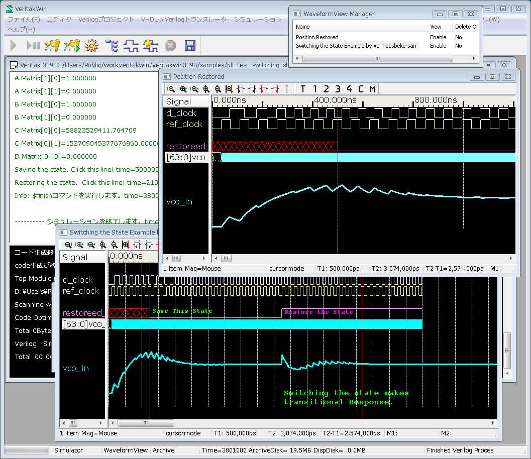
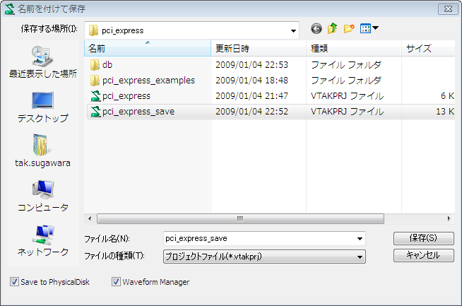
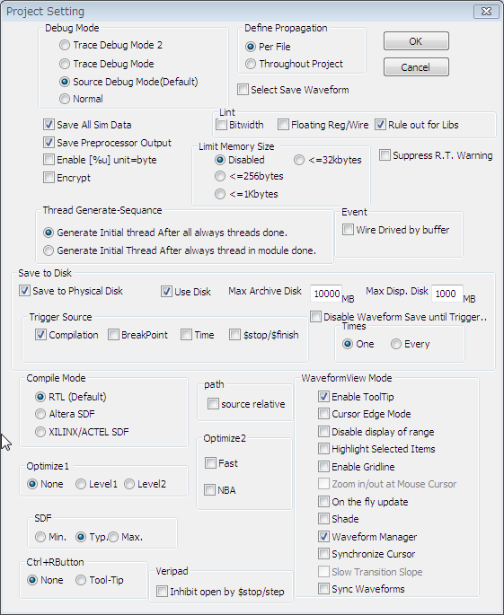
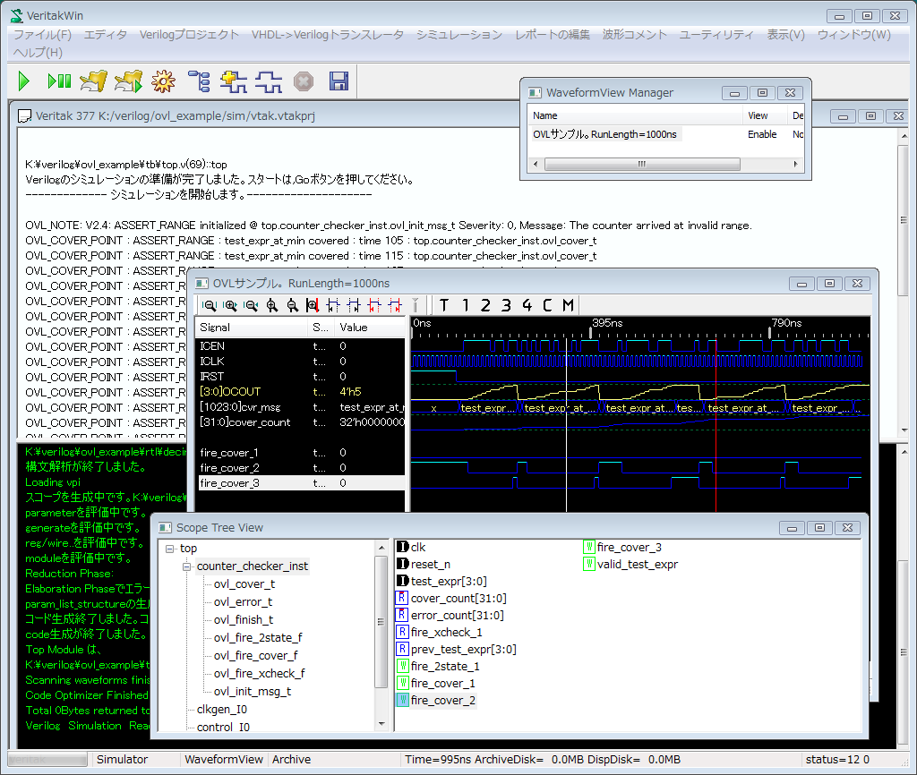
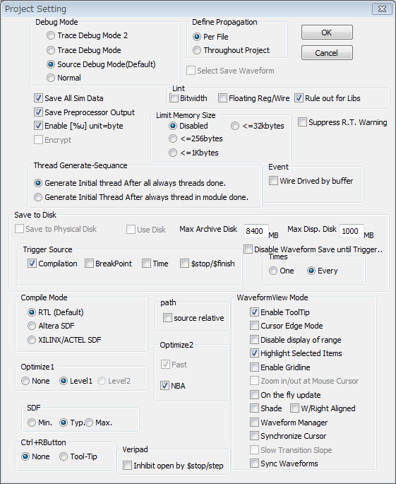
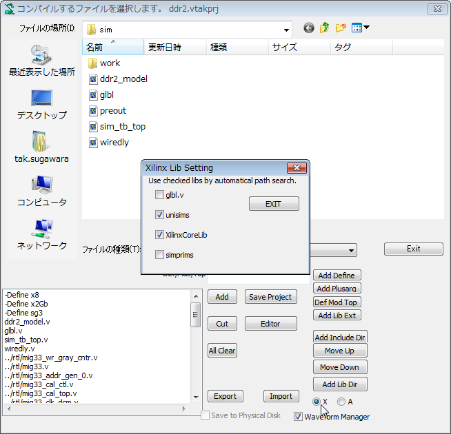